Basics of computer networks. Subject number 3. Protocols of lower levels (transport, network and channel)
Greetings to all readers. It's finally time to talk about the protocols that are on the lower levels. In this article, the protocols of the link, network and transport layers will be analyzed. Sit back and read to your health.
Content
1) Basic network terms, OSI network model and TCP / IP protocol stack.
2) Top-level protocols.
3) Protocols of lower levels (transport, network and channel).
4) Network devices and types of cables used.
5) The concept of IP addressing, subnet masks and their calculation.
6) The concept of VLAN, Trunk and VTP and DTP protocols.
7) Spanning Tree Protocol: STP.
8) Channel Aggregation Protocol: Etherchannel.
9) Routing: static and dynamic on the example of RIP, OSPF and EIGRP.
10) Network Address Translation: NAT and PAT.
11) Reservation protocols for the first transition: FHRP.
12) Computer network security and virtual private networks: VPN.
13) Global networks and protocols used: PPP, HDLC, Frame Relay.
14) Introduction to IPv6 configuration and routing.
15) Network management and network monitoring.
PS Perhaps over time, the list will be added.
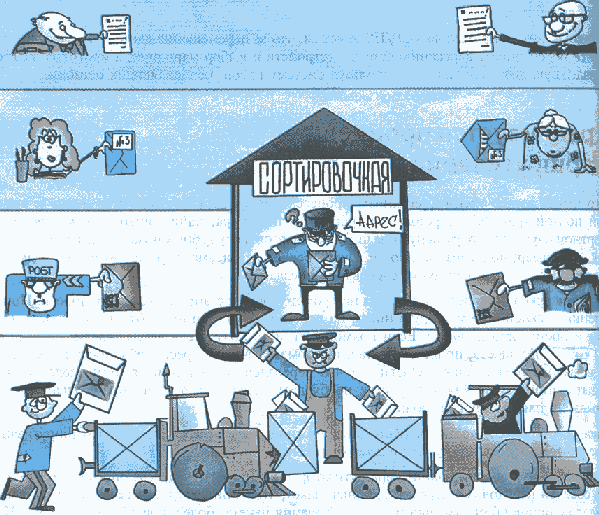
As you remember, I have already said that in networks it is important to strictly adhere to all the rules for proper operation. Namely the process of encapsulation and de-encapsulation. Therefore, when in the previous article we talked about the protocols of the upper levels, I casually mentioned some of the protocols of the lower levels, as they constantly got out and reminded about themselves. I will explain why. Look now at the picture above. Here is the work of the mail. Look at the two bald uncles at the top who wrote the letter and glow with happiness. But there will be no sense from the letter if the addressee does not see it. For this they will use the postal service. Their letter will take the employee of the post office and put in an envelope. She will sign the envelope so that it is clear from whom it is and to whom. Then the courier will take this letter and take it to the sorting center. Below is a little man in a cap and apron, who juggles letters. He knows where to put the letter so that it reaches the addressee. And at the very bottom of the train, which is a transportation hub. Note that the role of each is important for the successful sending and delivery of the letter.
In networks all the same. You decided to climb the site and read the news. Type in the browser address of the site. Further your computer as it should request these pages. And here already come to the aid of the protocols below, which are the transport hub. Here, each level can be compared with the above-described personalities in the figure.
')
I will bring all this gimp to a common denominator and share an example that I once brought for myself. You have a network terminating device. No matter the computer, laptop, tablet smartphone or something. Each of these devices operates on a TCP / IP stack. So, it follows its rules.
1) Application level. Here the network application itself works. That is, a web browser that runs, for example, from a computer.
2) Transport level. An application or service must have a port that it listens on and can connect to.
3) Network level. Here is the IP address. It is also called the logical address of the device on the network. With it, you can connect with a computer that is running this same browser, which means that you can reach the application itself. Having this address, he is a member of the network and can communicate with other members
4) Channel level. This is the network card itself or the antenna. That is, the transmitter and receiver. It has a physical address to identify this network card. Cables, connectors also belong here. This is an environment that will connect the computer with other participants.
Let's start with the lowest level. This is the channel and physical layer, when viewed from the point of view of the OSI model and the access level, when viewed from the height of the TCP / IP protocol stack. We use TCP / IP, so I will speak from her point of view. The access level, as you understand, unites the physical and data link layer.
Physical level Or as they like to call it "electrical level". Sets the signal parameters, as well as the type and shape of the signal. If, for example, Ethernet is used (which transmits data using a wire), then what is the modulation, voltage, current. If this is Wi-Fi, which radio waves should be used, frequency, amplitude. This level includes network cards, Wi-Fi antennas, and connectors. At this level, such a concept is introduced as bits. This is a unit of measure for information transmitted.
Channel level. This level is used to transmit not just bits, but meaningful sequences of these bits. Used to transfer data in a single channel environment. What does this mean, I will describe later. At this level, work MAC-addresses, which are also called physical addresses.
The term "physical addresses" is not just entered. Each network card or antenna has a wired address that the manufacturer assigns to it. In the previous article I mentioned the term "protocols". Only there it was the top-level protocols, and if more precisely, the application. At the link level, their own protocols work and their number is not small. The most popular are Ethernet (used in local networks), PPP and HDLC (they are used in global networks). This is by no means all, but Cisco only considers them in its CCNA certification.
It's hard to understand all this in the form of a solid dry text, so I will explain in the picture.

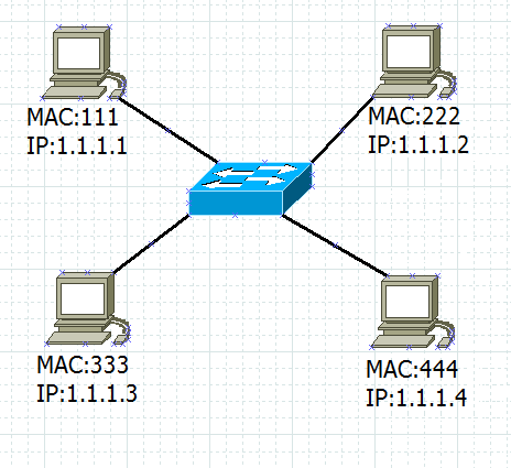
Forget now about IP addresses, OSI model and TCP / IP protocol stack. You have 4 computers and a switch. Do not pay attention to the switch, as this is a regular box for connecting computers. Each computer has its own MAC address that identifies it on the network. It must be unique. Even though I presented them with 3 digits, far from it. Now this picture is only for logical understanding, and how it works in real life, I will write below.
So. If one of the computers wants to send something to another computer, then he will need to know only the MAC address of the computer to which he sends. If the upper left computer with the MAC address 111 wants to send something to the lower right computer, it will send it without any problems if it knows that the addressee has the 444 MAC address.
These 4 computers form a simple local area network and one channel environment. Hence the name of the level. But for correct operation of nodes in TCP / IP networks, there is not enough addressing at the data link layer. It is also important to address at the network level, which is known to everyone as IP addressing.
Now we remember about IP-addresses. And assign them to our computers.
I assigned the addresses symbolically in order to understand how they work at a basic level. These two addresses (channel and network) work in close connection with each other and cannot work separately. I'll explain why. In our daily life, we work only with IP addresses or names, about which there was a whole chapter in the previous article. We don't actually work with MAC addresses. The computers themselves work with them. Now I will simulate the situation. I am sitting at the top left computer with IP: 1.1.1.1 and MAC: 111. I wanted to contact the bottom right computer and check if it is alive or not. I can contact him if I know his IP address. The MAC address is not interesting to me. I know that his IP address is 1.1.1.4. And I decide to use the ping utility (node availability check utility).
Now the important thing. The computer understands that it does not know the MAC address of the computer whose availability is to be checked. In order to find out the MAC address by IP address, they invented the ARP protocol. I will write about it in detail later. Now I want you to understand the dependencies of the MAC address and IP address. So, he starts shouting to the whole network: “Who is 1.1.1.4”. This call will be heard by all members of the network and, if there is one node that has this IP address, it will respond. I have such a computer present and in response to this shout, he will answer: “1.1.1.4 is me. My MAC is 444. My computer will receive this message and will be able to continue what I told him.
Next you need to learn how to distinguish one subnet from another. And as the computer understands, it is on the same subnet with another node or in different ones. For this, a subnet mask comes to the rescue. There are many masks and at first it seems scary, but I assure you that it only seems so at first. A whole article will be devoted to her and there you will know all her secrets. At this stage, I will show how it works.
If you have ever climbed into the settings of network adapters or registered a static address that the provider informed you, then you saw the "subnet mask" field. It is recorded in the same format as the IP address, default gateway and DNS. These are four octets separated by dots. If you have never seen this, you can open a command prompt and type ipconfig in it. You will see something similar.
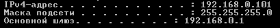
This is a screenshot from the command line of my laptop. I'm sitting at a home access point, which has a mask of 255.255.255.0. This is probably the easiest mask to explain, and most likely you have it exactly the same. What is the essence. The first 3 octets (they are fixed) show the network address, and 4 octets (it is dynamic) shows the address of the host. In other words, this mask shows that the first 3 octets need to be checked completely, and the fourth one can be free from 0 - 255. In general, this is a crude formulation. Because with such a mask will be free from 1 to 254, where 0 will go under the network address, and 255 under the broadcast address. But in any case, this is the limit of one channel environment. That is, when a node needs to send a message to another node, it takes its address and imposes a mask on it, and if the network address (fixed part) converges with its address, then they are in the same channel medium. I explain on the example of the same picture.
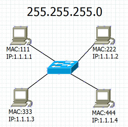
I sit behind the top left computer and I want to send the bottom right. I know his IP address and MAC address. I need to understand whether we are in the same channel environment. Its address is 1.1.1.4 and mask 255.255.255.0. The mask tells me that 3 octets are fixed and should not change, and the fourth one can be any one between 1 and 254. I put a mask on its address and on my address and look at coincidences and differences.
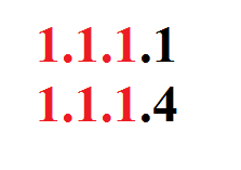
Red highlighted the area that is responsible for the network. As you can see, the 2 hosts it is the same. So they are on the same subnet.
Upgrading the network and showing you a little differently.
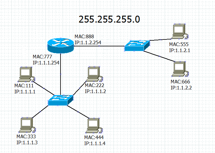
Added round device. It is called a router or router. The word is familiar to everyone. Its main role is to connect networks and choose the best route, which will be discussed in more detail later. And one switch was added to the right, with which 2 computers are connected. The mask for all devices has not changed (255.255.255.0).
Look carefully at the addresses of all devices. You may notice that the new octets and the old ones are different in the 3rd octet. Let's deal with this. I also sit at the computer with MAC: 111 and IP: 1.1.1.1. I want to send information to one of the new sites. Let it be the top right computer with MAC: 555 and IP: 1.1.2.1. Mask and look.
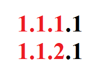
And here is another picture. 3rd octets are different, which means that the nodes are in different networks (more correctly subnets). To resolve such situations, there is a default gateway in the settings of each operating system. It is also called the “gateway of last resort”. It is used, just in case when it is necessary to send information to a node located in another channel environment. For my company, the gateway address is 1.1.1.254. And for the computer to which I send the data 1.1.2.254. The logic of work is simple. If a node that was in the same channel environment received information directly, then for a node located in another channel environment, the path will be through the router.
My computer knows that the gateway address is 1.1.1.254. He will shout to the entire network: "1.1.1.254 respond." All participants in the channel environment will receive this message, but only those who are sitting at this address will respond. That is a router. He will send the answer, and only after that my computer will send the data to the address 1.1.2.254. And pay attention. At the data link layer, the data will be sent to the MAC: 777, and on the network, to the IP: 1.1.2.1. This means that the MAC address is transmitted only in its channel environment, and the network address does not change all its way. When the router receives the info, it will understand that at the link level it was meant for him, but when he sees the IP address, he will understand that he is an intermediate link and must be transferred to another channel medium. His second port looks to the correct subnet. So it all came true to him. But he does not know the destination MAC address. He also starts shouting to the whole network: “Who is 1.1.2.1?”. And the computer with the MAC address 555 answers it. I think that the logic of the work is clear.
Throughout the two previous articles and the current one, the term “MAC address” has been mentioned many times. Let's see what it is.
As I said, this is a unique identifier for a network device. It is unique and should not be repeated anywhere. It consists of 48 bits, of which the first 24 bits is the unique identifier of the organization, which is assigned by the IEEE (Institute of Electrical and Electronics Engineers) committee. And the second 24 bits are assigned by the hardware manufacturer. It looks like this.

Write it down in different ways. For example:
1) 00-50-56-C0-00-08
2) 00: 50: 56: C0: 00: 08
3) 0050.560.0008
As you can see, the same address can be written in different ways. It is usually not shared, but recorded together. The main thing to know is that the MAC address always consists of 48 bits and consists of 12 letters and / or numbers. You can see it in different ways. For example, in Windows, open a command prompt and type ipconfig / all. Many manufacturers still write it on the box or on the back of the device.

So you can look at your Wi-Fi access point and see a similar entry. At the very beginning, I showed the MAC addresses in 3 digits, which is not true. In that context, I used them only for ease of explanation, so as not to confuse you with long incomprehensible records. Just below, when it comes to practice, you will see them as they really are.
Once we parsed the address at the link level, it's time to parse the protocol that works at this level. Currently the most popular protocol used in local networks is Ethernet . IEEE described it as 802.3 standard. So, all versions that start with 802.3 belong to it. For example, 802.3z is a GigabitEthernet through a fiber-optic cable; 1 Gbps, and 802.3af is power over Ethernet (PoE).
By the way, I did not say about the organization IEEE (Eng. Institute of Electrical and Electronics Engineers) . This organization develops standards for everything related to radio electronics and electrical engineering. On their website you can find a lot of documentation on existing technologies. This is what they give out on request "Ethernet"

Let's see what it consists of. Since the protocol itself is old (invented in 1973), it was modernized many times and changed its format. On the Internet, you can find all of its options, but I will give the one that Cisco brought when I was studying.

1) Preamble. The field used to indicate the start of a frame. That is, so that the receiver can understand where the beginning of the new frame is. Previously, when a common bus topology was used and there were collisions, the preamble helped prevent collisions.
2) The recipient's MAC address. The field where the recipient's address is written.
3) The MAC address of the sender. Accordingly, the address of the sender is recorded here.
4) Type (length). Previously, this field indicated to which upstream protocol the frame was transmitted, but later it was refused and entered the “Length” field. It indicates the length of the data field, which varies from 46-1500 bytes.
5) SNAP / LLC field + data. Just SNAP / LLC indicates which upstream protocol to transmit frame. It can be IP, IPX and other network layer protocols. This field also contains data obtained from higher levels.
6) FCS (from the English. Frame Check Sequence - checksum frame). The field in which the check-sum is calculated. According to it, the recipient understands whether the frame is beaten or not.
In the course of writing this article and subsequent, other data link layer protocols will be affected. So far, the above is enough to understand his work.
Go to the network level, and here we are met by the sensational IP protocol. Since we are talking about the network level, it means that the protocol operating at this level must somehow be able to transfer data from one channel medium to another. But first, let's see what the protocol is and what it consists of.
IP (from the English. Internet Protocol). A protocol for the TCP / IP family that was developed in the 1980s. As I said earlier, it is used to connect separate computer networks among themselves. Also important is its addressing function, which is called
IP address . Currently, there are 2 protocol versions: IPv4 and IPv6. A few words about them:
1) IPv4. Uses 32-bit addresses, which are written in the format of four decimal numbers (from 0 to 255), separated by dots. For example, the address is 192.168.0.4. Each number separated by dots is called an octet. This is the most popular version to date.
2) IPv6. Uses 128-bit addresses that are written in the format of eight four-digit hexadecimal numbers (from 0 to F). For example, address 2001: 0db8: 11a3: 09d7: 1f34: 8a2e: 07a0: 765d. Each number separated by dots is called a hextet. At the dawn of universal computerization, there was a problem. IP addresses began to end and a new protocol was needed that could provide more addresses. This is how the IPv6 protocol appeared in 1996. But thanks to the NAT technology, which will be discussed later, the problem of lack of addresses has been partially solved, and, in this regard, the introduction of IPv6 has been delayed until today.
I think it is clear that both versions are intended for the same purposes. This article will discuss the IPv4 protocol. A separate article will be written about IPv6.
So, the IP protocol works with a block of information that is commonly called an IP packet. Consider its structure.

1) Version. IPv4 or IPv6.
2) IHL (from the English. Internet Header Length - the size of the header). Since many of the fields shown in the picture are not fixed, this field considers the size of the header.
3) Type of service. Serves the size of the QoS (Quality of Service) queues. It does this with the help of a byte, which indicates a certain set of criteria (time delay, bandwidth, reliability, etc.)
4) Package length. Package size. If IHL is responsible only for the size of the fields in the header (the header is all the fields in the picture, except for the data field), then the packet length is responsible for the entire packet, including user data.
5) Time to live (TTL- Time To Live). The field used to prevent a packet's circular path.When passing through a router, the value decreases by one, and when it reaches zero, the packet is dropped.
6) Protocol. What superior protocol is the packet intended for (TCP, UDP)?
7) Header checksum. Here is considered the integrity of the header fields. Not data! The data is verified by the corresponding field on the data link layer.
8) Options. IP. . - , . , ( ), , - . , , .
9) . , IP. .
10) .It just contains the data obtained from the higher levels. Just above, I showed that there is also a data field in the Ethernet frame. And this IP packet will be included in its data field. It is important to remember that the maximum size of an Ethernet frame is 1500 bytes, while the IP packet size can be 20 Kbytes. Accordingly, the entire packet does not fit into the data frame of the Ethernet frame. Therefore, the package is divided and sent in parts. And for this we use 3 fields below.
11) Identifier. This is a 4-byte number that indicates that all parts of a divided packet are one and the same.
12) Flags. Indicates that this is not a single, but a fragmented packet.
13) Fragment offset. Shift relative to the first fragment. That is, this is a numbering that will help put the IP packet together.
14) the sender's IP address and the recipient's IP address. Accordingly, these 2 fields indicate from whom and for whom the package.
This is what the IP packet looks like. Of course, for beginners, the values of many fields will seem to be not entirely clear, but in the future this will be in the head. For example: the “Lifetime (TTL)” field. His work will become clear when you understand how routing works. I can give advice that I apply myself. If you see an incomprehensible term, write it out separately and, if you have free time, try to make out. If you can’t get into your head, then put it aside and return to studying it a bit later. The main thing is not to throw and finally finish it off.
Stayed last level from the TCP / IP stack. This is a transport level.. A few words about him. It is designed to deliver data to a specific application, which it identifies by port number. Depending on the protocol, it performs different tasks. For example, file fragmentation, delivery control, multiplexing and data streaming. The two most famous transport protocols are UDP and TCP. Let's talk about each of them in more detail, and start with UDP, because of its simplicity. Well, according to tradition, I show what it consists of.

1) . , . , , .
2) . , . , , , , 80- ( HTTP).
3) UDP. UDP. 8 65535 .
4) UDP. . , .
5) . . , - -, .
As you can see, he has not so many fields. Its tasks are the numbering of the ports and to check whether the frame has crashed or not. The protocol is simple and not resource intensive. However, he cannot provide control of the delivery and re-request broken pieces of information. Of the known services that work with this protocol is DHCP, TFTP. They were considered in the previous article when top-level protocols were being sorted out.
Moving on to a more complex protocol. We meet the TCP protocol. We look, from what consists, and we run on each field.
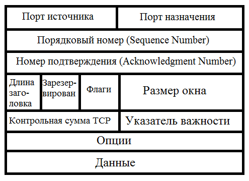
1) Source port and destination port. Perform the same roles as in UDP, namely port numbering.
2) Sequence number. The number that is used so that on the other side it is clear what this segment on the account.
3) Confirmation number. This field is used when delivery is expected or delivery is confirmed. To do this, use the ACK parameter.
4) The length of the header. It is used to understand what size the TCP header (these are all the fields shown in the picture above, except for the data field), and what is the data.
5) Reserved flag. The value of this field must be set to zero. It is reserved for special needs. For example, to report network overloads.
6) Flags.In this field, special bits are set to establish or terminate the session.
7) Window size. , , . , . - . , 30 , 2-3 20 . 5, 10 . . , . . , , . , . , , . .
8) TCP checksum. Check the integrity of the TCP segment.
9) Index of importance. This is the offset of the last octet of important data relative to SEQ for packets with the URG flag set. It is used in life when it is necessary to control the flow or the state of the upper level protocol from the transmitting agent (for example, if the receiving agent can indirectly signal the transmitting agent that it does not cope with the data flow).
10) Options. Used for any advanced or optional parameters. For example, for the timestamp parameter, which is a kind of label indicating the time of the event that occurred.
11) Data. Almost the same as in the UDP protocol. Here data from higher level are encapsulated.
We saw the structure of the TCP protocol and at the same time ended the conversation about the transport layer. The result was such a brief theory of protocols working at lower levels. I tried to explain as simply as possible. Now we will test this whole thing in practice and finish off a couple of questions.
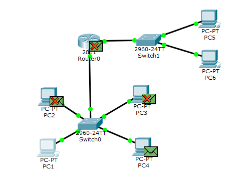
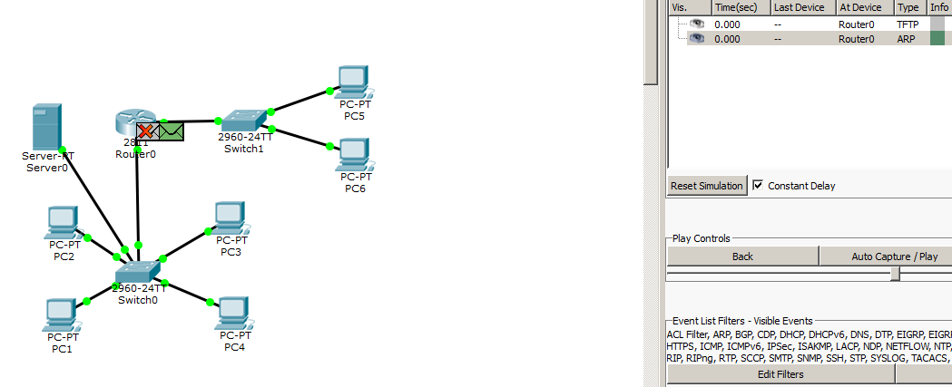
I open the CPT and assemble a scheme similar to one of the figures above.

Here we observe the first network consisting of 4 computers and a switch that connects these computers. And the 2nd network consisting of two computers and a switch. Combines these 2 networks with a router. Let us turn to setting up the devices and then simulate the situation that we considered at the very beginning in the picture.
I open PC1 and register the network settings.
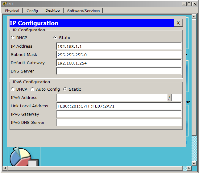
, :
1) IP- — 192.168.1.1
2) — 255.255.255.0. . , , 192.168.1, 1 254.
3) — 192.168.1.254. , .
, 3- , .
PC2:
1) IP- — 192.168.1.2
2) — 255.255.255.0.
3) — 192.168.1.254.
PC3:
1) IP- — 192.168.1.3
2) The subnet mask is 255.255.255.0.
3) The main gateway is 192.168.1.254.
PC4:
1) The IP address is 192.168.1.4.
2) The subnet mask is 255.255.255.0.
3) The main gateway is 192.168.1.254.
For now, let's stop at this setting and see how our local network works. Putting CPT into simulation mode. Suppose I am sitting at PC1, and I want to check the availability of PC4 with the ping command. I open the command line on PC1.

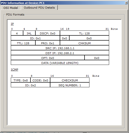
As soon as I press ENTER, 2 envelopes appear on the diagram.

One of them is ICMP, with which the ping command itself works. Immediately open it and look.

IP ICMP. , . , 4 IP, , IPv4. 2 IP- (SRC:192.168.1.1 DST:192.168.1.4).
ping . MAC- . , . ARP, MAC-. . . . !

1) The protocol type of the data link layer (Hardware type). I think it is clear from the name that the type of the data link layer is indicated here. We have so far considered only Ethernet. Its designation in this field is 0x0001.
2) Protocol type of network layer (Protocol type). Here, similarly, the type of network layer is indicated. The IPv4 code is 0x0800.
3) The length of the physical address in bytes (Hardware length). If this is a MAC address, then the size will be 6 bytes (or 48 bits).
4) The length of the logical address in bytes (Protocol length). If this is an IPv4 address, then the size will be 4 bytes (or 32 bits).
5) Operation code (Operation). Transaction code of the sender. If this is a request, then the code is 0001. In the case of a response, it is 0002.
6) Physical sender address (Sender hardware address).MAC address of the sender.
7) The logical address of the sender (Sender protocol address). IP address of the sender.
8) The physical address of the recipient (Target hardware address). MAC address of the recipient. If this is a request, then, as a rule, the address is unknown and this field remains empty.
9) The logical address of the recipient (Target protocol address). Recipient's IP address.
Now that we know what it consists of, we can look at its work in the CPT. I click on the second envelope and watch the following picture.
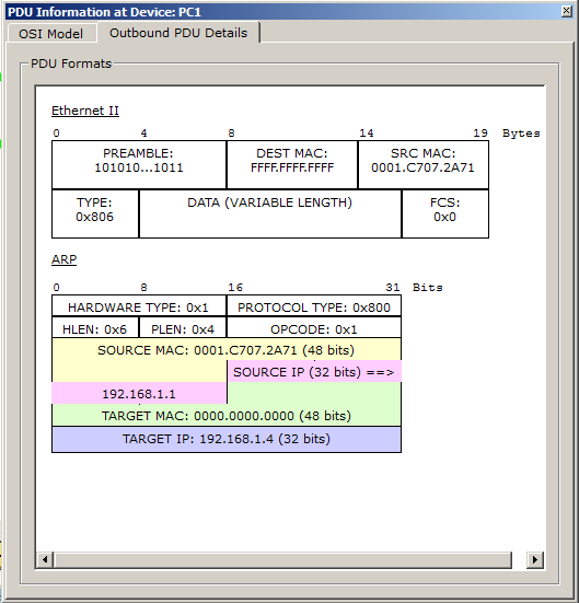
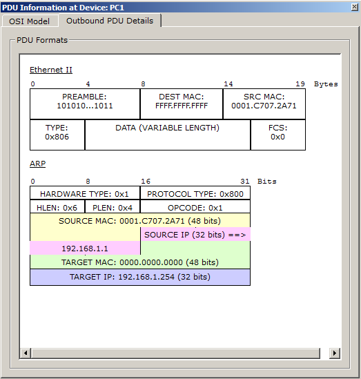
ARP . 2- Ethernet. .
1) — , .
2) MAC- . MAC- , , FF-FF-FF-FF-FF-FF ( ).
3) — . 0x806 , ARP. , , , . -. , 2- OSI, - , 3-. , . , .
- . , - .
ARP .
1) Hardware Type — . CPT 0x1 (, 0x0001). Ethernet.
2) Protocol Type — . 0x800 — IPv4.
3) HLEN- the length of the physical address. 0x6 means 6 bytes. That's right (the MAC address is 6 bytes).
4) PLEN - the length of the network address. 0x4 means 4 bytes (IP address is 4 bytes).
5) OPCODE - opcode . 0x1 means it is a request.
6) Source Mac - here the MAC address of the sender. You can compare it with the address in the Ethernet protocol field and make sure it is correct.
7) Source IP - the IP address of the sender.
8) MAC Target - since this is a request and the channel address is not known, it is empty. CPT showed it with zeros, which is equivalent.
9) Target IP - the recipient's IP address. Just the address that we ping.
Let's see what will happen next in the network.
ARP . PC4. , .
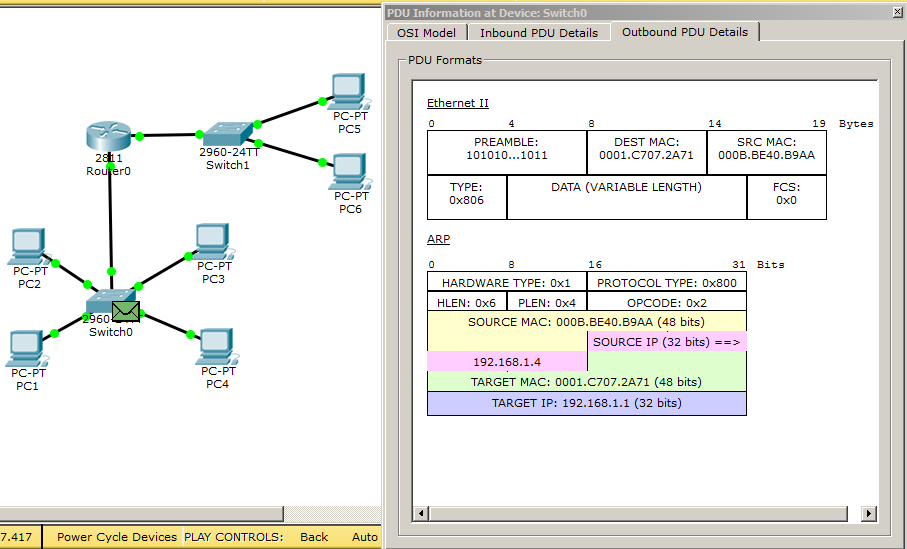
- . , :
1) Ethernet MAC- PC4, MAC- , PC1.
2) OPCODE 0x2, .
3) ARP. Source MAC Destination MAC , Ethernet. Source IP — 192.168.1.4 (PC4), Destination IP — 192.168.1.1 (PC1).
PC1, ICMP-, ping.

. , 3- : Ethernet, IP Ping.
1) Ethernet , MAC- — PC1, MAC- — PC4, Type — 0x800 ( IPv4)
2) IP , — 4, IPv4. IP- — PC1, IP- — PC4.
3) ICMP , Type — 0x8 (-).
-, , PC4.

CPT, . ICMP - , . . .
, , PC4. Ethernet IP . Type ICMP 0x8 0x0 ( -).
, PC1, PC1 . Let's check.

And really.There was a record of PC4 availability, data size (32 bytes), time delay (8 ms) and TTL or lifetime (128). TTL shows how many routers overcame the packet. My package was walking within the local network, so this field has not changed.
By default, the ping sends 4 requests. Therefore, PC1 will generate 3 more similar ICMP. I will not show the path of each packet, but I will give the final console output on PC1.
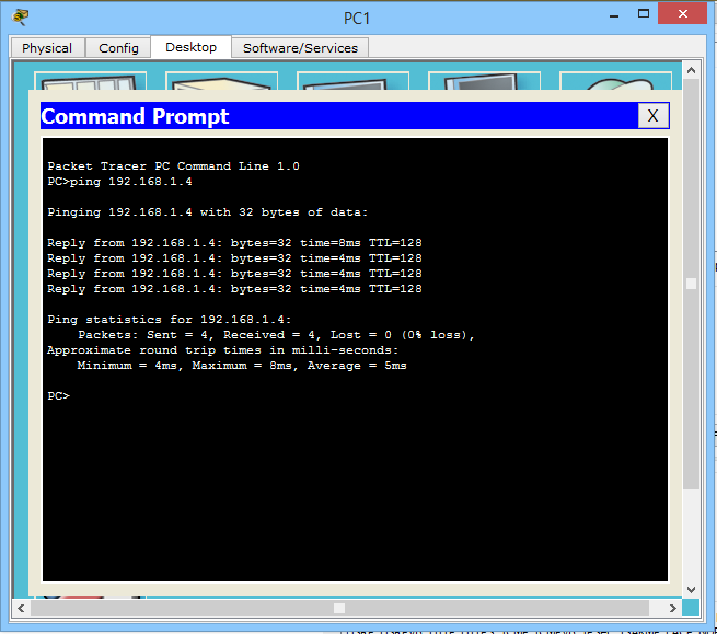
And as you can see, there are really 4 answers. Note that the first one arrived with a delay of 8 ms, and the last 3 arrived at 4 ms. This is related to the operation of the ARP protocol, since at first PC1 did not know the MAC address of PC4 and waited for it to be informed. Although in CPT there is a situation that in real time, the first packet is generally lost. This is especially true when the availability of a host in a different channel environment is checked.
We saw how data transmission in one channel environment works. Now let's see what happens if the hosts are in different channel environments or subnets. Let me remind you that the network is not configured to the end. Namely, you need to configure the router and the second subnet. What we do now.
I open the computer named PC5 and register the network settings.
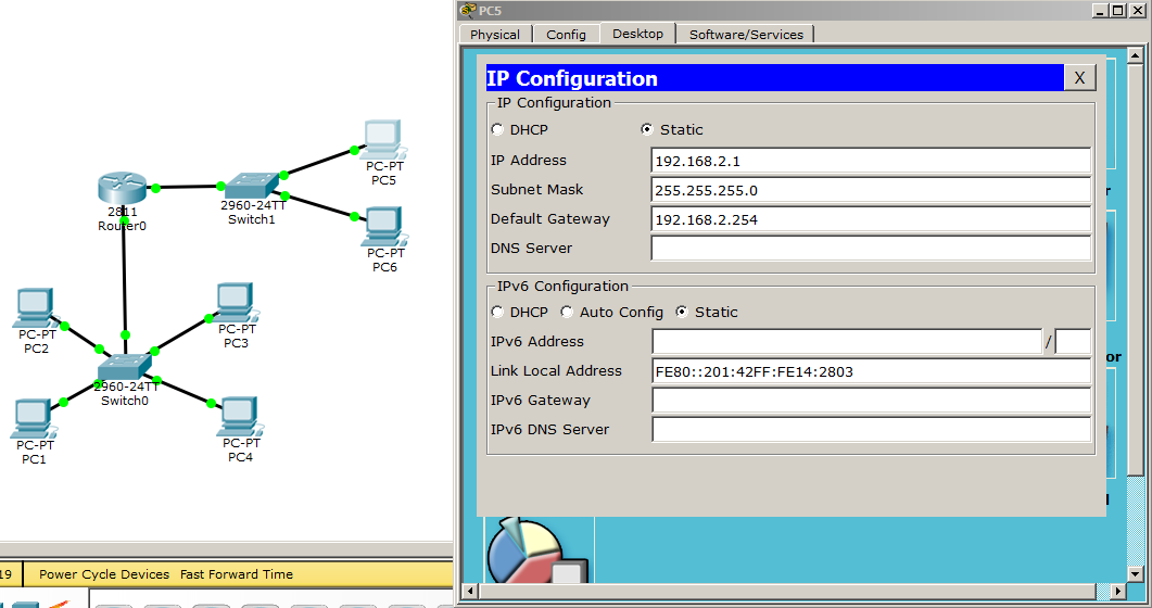
Note that the network addressing in the first channel environment was 192.168.1.X, and in the 2nd channel 192.168.2.X. With a mask of 255.255.255.0, this means that the first 3 octets are fixed, and the 4th octet is in the range from 1 to 254. And since our 3rd octets are different, they are different channel environments.
Here are the PC6 settings:
1) IP address - 192.168.2.2
2) Subnet mask - 255.255.255.0
3) The main gateway - 192.168.2.254 The
hosts in the 2nd channel environment are configured and work fine. In order for them to be able to communicate with hosts from the 1st channel channel, you need to configure the router that connects these environments. The router is configured via the CLI (that is, in the console view) and it will be easier to bring here not screenshots, but commands.
1) Router> enable -switch to privileged mode
2) Router # configure terminal - switch to global configuration mode
3) Router (config) #interface fastEthernet 0/0 - go to setting port 0/0, which looks at the first channel environment
4) Router (config-if ) #ip address 192.168.1.254 255.255.255.0 - hang the IP address on this port. Since this port will be the main gateway for the 1st channel environment, we indicate to it the IP that was assigned to the hosts
5) Router (config-if) #no shutdown - enable this interface. By default, all ports on the tsiskov routers are disabled
6) Router (config-if) #exit - exit fastEthernet 0/0 configuration mode
7) Router (config) #interface fastEthernet 0/1 - 0/1,
8) Router(config-if)#ip address 192.168.2.254 255.255.255.0 — , 2-
9) Router(config-if)#no shutdown —
10) Router(config-if)#end — ,
11) Router#copy running-config startup-config —
. «show ip route». .

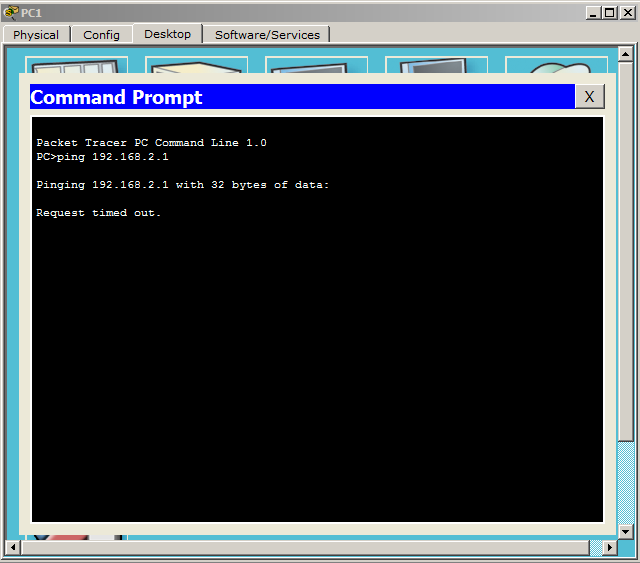
, , 1- , 2-. Fine. — PC5 PC1. I try. CPT . 192.168.2.1.
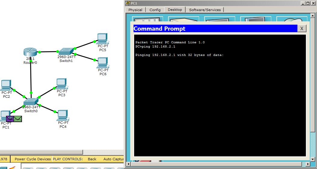
As soon as I press ENTER, 2 envelopes appear immediately: ICMP and ARP. Let's stop and look at them in more detail. Now it may seem that the transfer between different channel environments is no different from transmission in one channel environment, but this is not so. And now you will see it.
First look at the ICMP.
Here, in principle, nothing interesting. The source field is the IP address of PC1, and the destination field is the IP address of PC5.
What will happen next. PC1 sees that the availability of a host in a different channel environment is checked (by masking its own IP address and the recipient's IP address). And besides the IP address, he does not know anything about the recipient. Accordingly, it is not possible to send an ICMP packet in this form. But he knows that he has a main gateway, which most likely knows something about the channel environment in which PC5 is located. But there is another difficulty. He knows the IP address of the gateway (which I registered to him in the network settings), but does not know his MAC address. Here he comes to the aid of the ARP protocol, which polls all participants in the channel environment and finds its MAC address. Let's see how the fields are filled.
At the link layer (Ethernet protocol): The source field is the MAC address of PC1, and the destination field is the broadcast address (that is, all participants).
And a little higher (ARP protocol):
1) SOURCE MAC is the same PC1, and DESTINATION MAC is empty (the one for whom this request is intended to fill it).
2) SOURCE IP address is PC1, but DESTINATION IP is the address of the main gateway.
We look what will happen next.

3 computers dropped the packet, and only the router realized that it was for him. We look, than will answer.
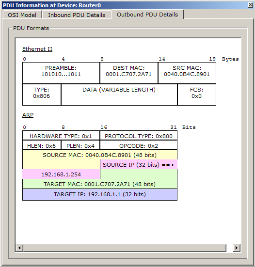
Ethernet:
1) Source MAC - here it inserts its MAC address (namely the MAC address fastEthernet0 / 0).
2) Destination MAC - this is the PC1 MAC address (that is, the one who requested).
ARP:
1) Source MAC and Destination MAC in the same way as in Ethernet.
2) Source IP - your IP address.
3) Target IP - IP address of PC1.
Go ahead.

As soon as ARP comes from the router to PC1, then PC1 immediately sends an ICMP message to the router (or the default gateway). And here I ask you to pay special attention. Namely, on the source and destination fields (both in the Ethernet protocol and in the IP protocol).
1) SRC MAC: here is the MAC address of PC1.
2) MAC DEST: Router MAC Address.
3) SRC IP: PC1 IP address.
4) DST IP: PC5 IP address.
What does it mean. Network-level addresses (i.e., IP addresses) do not change to know from whom and to whom information is intended. And the channel level addresses (MAC addresses) can easily change, moving from one channel environment to another. It is very important to understand and remember!
See what happens. The packet reaches the router and is immediately crossed out. And all because he does not know the MAC address of PC5. Now he forms an ARP request and tries to find out. I give a screenshot of this request.

Then PC5 will receive it and form the answer.

As soon as this answer reaches the router, it will know the channel address of PC5. But that's what happened. While the gimp with the ARP of the router and PC5 dragged on, PC1 has timed out waiting for a response sent by ICMP. Show the picture.
After the timeout expires, it forms the second ICMP, the answer of which will already come without problems, as MAC addresses are known. Following it will form the 3rd and 4th ICMP. I give the final result.

And if you look closely, you can see that the TTL has dropped by one and is now equal to 127. This happened because the packet overcame one transit leg (router).
This is how data transfer from one channel medium to another (or from one network to another) works. Here, by the way, it does not matter how many channel mediums you will need to overcome in order to get to the recipient. The principle will still be like that.
In the previous article, when the top-level protocols were considered, we were a little concerned with the transport level. I propose to recall this level and firmly fix.
I will begin, as always, with simple. And this is UDP protocol. As I said above, it is used to transfer data to a specific protocol of a higher level. He does this with the help of ports. One of the protocols working with UDP is TFTP (Trivial File Transfer Protocol). We considered this protocol in the previous article. Therefore, difficulties should arise. For the demonstration, you will need to add a server with TFTP service to the network.
Server settings are as follows:
1) IP address - 192.168.1.5
2) Subnet Mask - 255.255.255.0
3) The main gateway is 192.168.1.254
TFTP service is enabled by default, but it's best to check. Next, I switch the CPT to the simulation mode and try to save the configuration of the router to the TFTP server:
1) Router> enable - switch to the privileged mode.
2) Router # copy startup-config tftp: - I write the copy command (i.e., copy), then the startup-config (what to copy) and tftp: (where to copy).
3) Address or name of remote host []? 192.168.1.5 - a message is sent asking for the address or server name where I write its address.
4) Destination filename [Router-confg]? - then he asks under what name to save it on the server and suggests a standard name. It suits me, and I press ENTER.
Immediately the router forms 2 envelopes. One of them is crossed out TFTP, and the second is ARP. I think, we guessed that it is crossed out because he does not know the MAC address of the server.
I will miss the moment of the ARP, as we have seen enough of it.

Let's take a closer look at what the router sends to the server.
Ethernet:
1) Source MAC - address of the router.
2) Destination MAC address of the server.
3) Type - 0x800 (means that the IP protocol works above).
IP:
1) Protocol - 0x11 (means that the UDP protocol works above).
2) Source IP address of the router.
3) Destination IP address of the server.
UDP:
1) Source Port - dynamically created port (1025).
2) Destination Port — the port that the TFTP server listens to (reserved port 69).
TFTP:
Here are the data itself.
This is how UDP works. He does not set up the session, does not require confirmation of delivery, and if something is lost, he does not ask again. His job is to specify the port number and send. What is going to happen next does not interest him. But there are cases when it does not suit and all these parameters are critically important. Then TCP comes to the rescue. Consider it using a web server and a web client. By the web server we will have the same TFTP server. We enable the HTTP service and request a page from PC1. Do not forget to switch CPT to simulation mode!
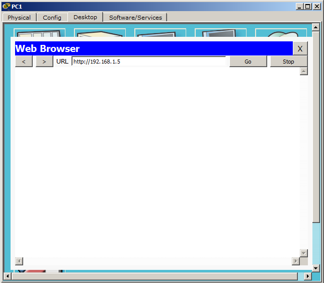
I type the web server address and press ENTER.
Before continuing, I will tell you about setting up a TCP session. I will try to present this process as simply as possible. This process is called a “three-way handshake” or “handshake”. What is the essence. The client sends a TCP segment with the "SYN" flag. Having received a segment, the server makes a decision. If he agrees to establish a connection, he sends a response segment with the "SYN + ACK" flag. If you do not agree, then sends a segment with the flag "RST". Next, the client look at the response segment. If there is a flag "SYN + ACK", then it responds with a segment with the flag "ACK" and a connection is established. If there is a flag "RST", then it stops trying to connect. After it is necessary to break the established connection, the client forms and sends a TCP segment with the “FIN + ACK” flag. The server for this segment responds with the same flag "FIN + ACK". Finally, the client sends the last TCP segment with the “ACK” flag. Now you will see how it works in practice.
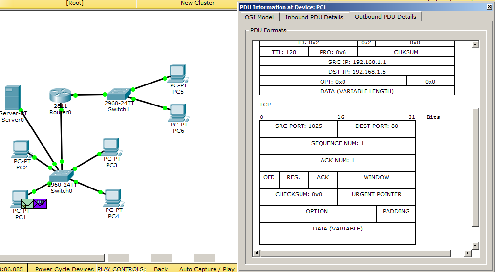
I switch attention to the network and see how PC1 forms a TCP segment.

I will not consider the fields of the Ethernet and IP protocols, since there is nothing new here, except for the Protocol field in the IP protocol. There is a value - 0x6. This suggests that TCP is used above.
But TCP is more interesting.
1) Source Port - 1025 (this is a dynamically generated port of the web client).
2) Destination Port - 80 (this is the reserved HTTP port).
3) Flag - SYN (request to establish a session)
We look, than the web server will respond.

It changes the port numbers in some places and sends a segment with the flag "SYN + ACK".
As soon as the client receives this segment, he immediately forms 2 messages. One of them is the TCP segment shown below, which is sent with the "ACK" flag.
And the second is HTTP, where the protocol version is indicated, which page and server address is.

His work was presented in a previous article. Therefore, I will not repeat. I will show you now closing the session.

As soon as the client receives the desired page, he no longer needs to maintain the connection and he initiates a break. Sends a segment with the “FIN + ACK” flag. We look further.
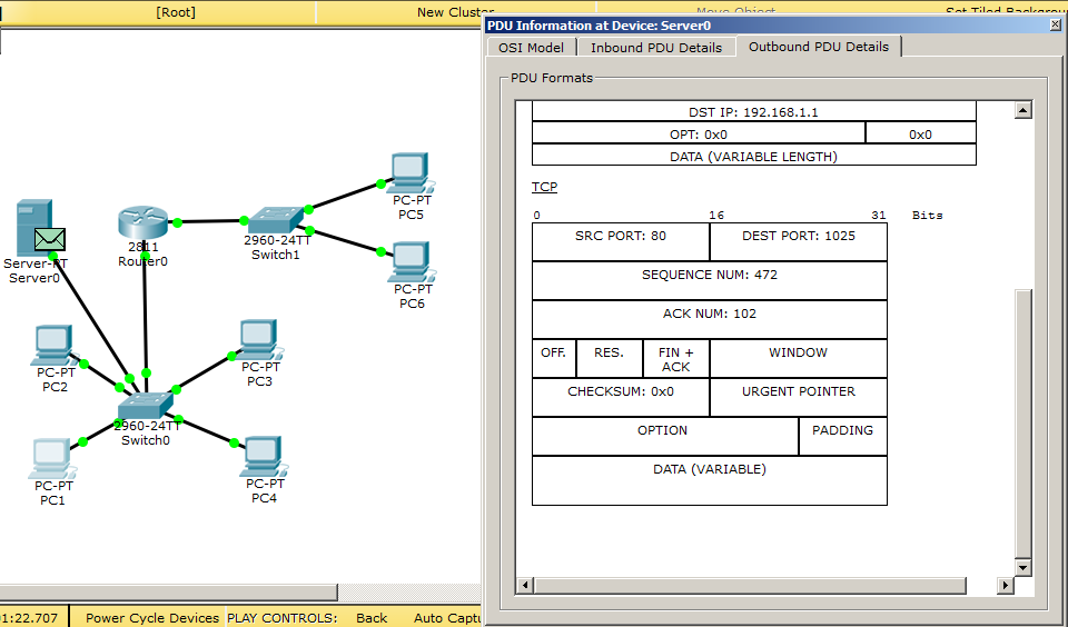
The server agrees to break the connection and sends back a segment with the same flag “FIN + ACK”.

Finally, the client forms the last TCP segment with the “ACK” flag and closes the connection.
We looked at how the TCP protocol works, and with it we’ve finished looking at the lower layer protocols. I provide a link to download this labs. At first I had an idea to follow the standard paved way, and write a separate article for each level, but then I realized that it was pointless to do it. Since at the time of writing the next article, most of the previous one is forgotten.
Well, the article comes to an end. I want to thank the user under the nickname remzalp for providing the picture and the other users who leave useful comments to the articles. It is very nice to see how people are interested, ask questions, lead objective and constructive disputes. It would be desirable, that the Russian-speaking IT-community developed more and more and the materials for studying in free access became more and more. Thank you for reading and see you at the next one.
Source: https://habr.com/ru/post/308636/
All Articles