How to stop being afraid and fall in love with mbed [Part 1]
We are engaged in the supply of electronic components. To do our job well, it is not enough just to be able to bring and sell electronic components - it is still important to be able to demonstrate their advantages. That is why we not only write review articles, but also create guidelines for the use of various “hardware” and develop small demonstration projects.
I will tell you about the history of the creation of one of such demonstration projects - I will consistently describe the process of creating a prototype device equipped with a capacitive touch screen and designed to measure relative humidity and temperature.
')
Of particular interest is the approach to writing firmware - software is completely written in the online IDE from mbed. That is, the program for the microcontroller was created on a single tab of Google Chrome and works equally well on debug boards from different manufacturers.
Content of the publication cycle:
The first part under the cut.
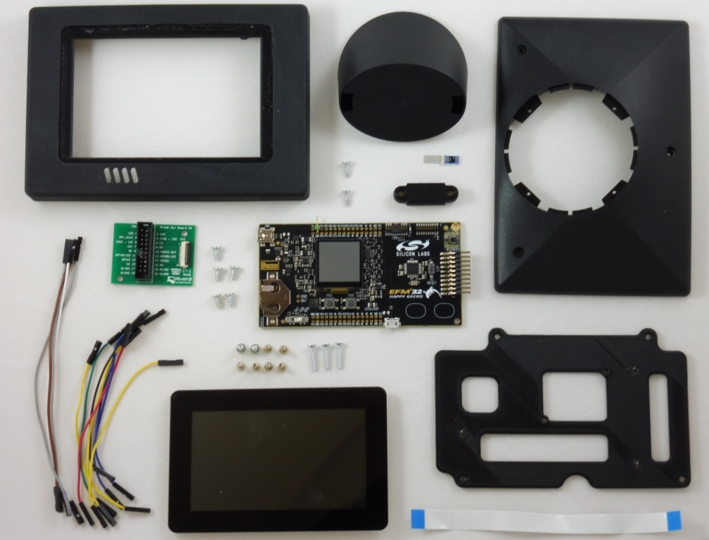
So, the device consists of three main components:
The protagonists of the play are the Riverdi display and the IST sensor, since the project is designed to demonstrate their capabilities. But as a control node, you can use any debugging board on which the necessary interfaces are implemented and displayed - SPI for TFT-display and I2C for sensor. In my case, when I really want to play around with mbed, its support in mbed IDE is added to the requirements for the microcontroller platform.

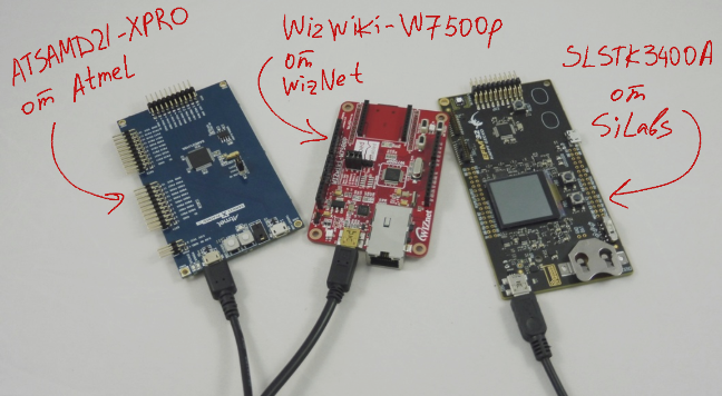
The SLSTK3400A board from Silicon Labs with the EFM32 Gecko series controller onboard was chosen as the base platform. In the first photo she is in the center. However, my goal is to create a program in mbed that would work on other mbed-based debugging boards. Therefore, different debugs from SiLabs, Atmel and Wiznet will be alternately included as a control module at each development stage.
Now consider the components in more detail.
HYT series sensors have already been devoted to an article on Habré , today I will give a less detailed description.

HYT-271 is a digital relative humidity sensor with I2C interface, which is manufactured by the Swiss company IST. Like most modern sensors of relative humidity, it has a capacitive sensing element and is equipped with an additional temperature sensor. The latter is necessary first of all for automatic thermal compensation of the results of humidity measurement, however, it is also an independent sensitive element from which it is possible to obtain data on the ambient temperature.
The key advantages of the HYT-271 sensor are high accuracy in measuring humidity and a very fast response. Such characteristics are in demand in the management of such technological processes as drying, evaporation and distillation - this is the widest class of tasks from making pasta to controlling the hardening of concrete structures.
High-end sensors are also needed in devices for measuring residual moisture, or, for example, in the climate control of rooms where moisture-sensitive materials like wood or grain are stored. Among the targeted applications are also incubators, medical equipment and other important tasks, among which there is no home weather station !!!
The price of sensors of this class in the Russian Federation is from 40 to 100 dollars. We offer HYT-271 individually from the warehouse for 37 euros, and for wholesale purchases the price naturally decreases. For example, if you order 50 sensors, the price will be about 30 euros per sensor. Well, there are discounts, contact .
Integral sensors with a digital interface are factory calibrated, so for work it is usually sufficient to connect the sensor to the control controller (in our case via the I2C interface) and master the data exchange protocol. The data exchange protocol describes the format of control commands and data packages. We will turn to one of the following articles to the software implementation of the HYT-271 sensor polling procedure.
HYT Series Sensor Documentation
Riverdi is a Polish manufacturer of TFT modules, i.e. TFT displays with integrated graphics controllers.
 Displays differ in size, parameters of the matrix, the presence of a capacitive or resistive touch screen and additional options such as a mounting frame. Most modern Riverdi displays are equipped with FTDI graphics controllers - the FT80x and FT81x microcircuits, which execute commands for drawing graphics primitives, process data from the touch input channel and the audio channel. In other words, FTDI microcircuits perform the role of a graphic coprocessor, on which all complex resource-intensive tasks are shifted from the main microcontroller. The program, which "turns" on the control microcontroller, uses the libraries from FTDI and with their help forms simple commands for managing the graphics module. For communication between the central controller and the FT80x / FT81x chip, I2C or SPI serial interface is used.
The order of control of the graphics controller and the features of FTDI development tools will also be discussed in the following articles.
The assortment of TFT modules can be found on the manufacturer’s website and on our website. On display with a diagonal of 2.83 ", 5" and 7 "just special prices are valid .
For the demonstration project, the RVT43ULFNWC00 uxTouch series TFT module is used. It has a 4.3 ”diagonal, capacitive touchscreen and an integrated graphics controller FT801.
UxTouch displays are the cutest of all existing Riverdi modules. They are made in a decorative frame, covered with protective glass and do not have external mounting fixtures and holes. To install the display in the case, an adhesive surface is provided, which is located on the back side of the decorative frame around the entire perimeter of the display. All this looks really great - when you twist the module in your hands, your hands and eyes that are used to the ipad do not feel any trick.
To interrogate the sensor and display the data on the TFT-display, in the presence of the FT801 chip, a high-performance microcontroller is not required. Most often, even an 8-bit crystal is enough, in this is actually the chip of using an FTDI graphics controller.
However, for the sake of my desire to get acquainted with mbed, I still use the ARM Cortex-M platform - I use the SLSTK3400A as the main working board, and the ATSAMD21-XPRO from Atmel and WIZwiki-W7500P from Wiznet as alternatives. In addition to the required I2C and SPI interfaces, target controllers have a fairly decent amount of memory - at least 64 KB Flash. This bonus will allow to realize not only the beautiful display of information received from the sensor, but also, for example, the storage of images.
On debug boards, we don’t need most of the available peripherals. SiLabs power metering circuits, Wiznet's hardware Ethernet, as well as endless controllers, touch and mechanical buttons, LEDs and LCDs - everything goes in the forest. We pay attention only to the presence of the built-in USB debugger and the conclusions of the necessary digital signals.
Now about mbed.
Mbed is a software platform for developing IoT devices based on microcontrollers with an ARM Cortex-M core. The platform is developed by the ARM company itself and manufacturers of microcontrollers. I will not touch on many of the mbed tools (cloud services, encryption tools, mbed OS, etc.). Only the online IDE, the mbed “base” library and drivers for pairing the debug card with other devices will be considered.
The mbed libraries provide a level of abstraction at which a program is written not for a specific STM32 / Atmel / NXP controller, but immediately for any platform that is supported in mbed. Platform support means that mbed calls correctly address the entire HAL of the target microcontroller, that mbed understands the topology of the debugging board, and that the debugging board is recognized on the PC as an external drive and is flashed by simply copying the binary file to this drive.
For instructions on how to register on developer.mbed.org, compile and run a demo program, detailed instructions have already been written. Here , for example, a guide to the flashing LED of my authorship.
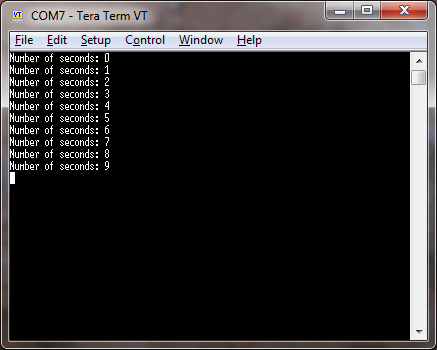
Therefore, we will immediately proceed to the preparation of the future project - a simple program for outputting the seconds counter to the serial port.
Create a project consisting of the main.cpp file and the mbed library package, compile the program, get the automatically downloaded binary file and copy it to the SLSTK3400A board, which is defined by the computer as an external disk.
Now, by running Terminal, we get the required data from the controller.
In order to generate firmware for the Atmel and Wiznet boards, it is enough to change the target platform,

After that, re-compile the project and copy the resulting file to the appropriate disk - XPLAINED or MBED (yes, the Koreans were different in inventing names).

On the Mac, the program immediately started working on all three boards, and on Windows it was necessary to install the mbed COM port driver . Without it, only the SiLabs board wanted to communicate via the serial interface. However, this is a regular situation, well described by ARM itself.
Here it is time to notice one of the main disadvantages of mbed: printf - this is in fact the only available debugging tool. In addition to debugging with breakpoints and access to the microcontroller registers, mbed has other obvious limitations. For example, universal peripheral drivers by definition cannot support all the features of the peripherals of each controller, that is, mbed may not have libraries for unusual modules or support for some non-standard modes of operation of your microcontroller's peripherals. And it can be exactly those modes and modules, because of which you chose your own klistall.
Also, of course, mbed is not the best tool for creating complex applications related to scheduling tasks and multithreading (although I am not aware of what the new mbed OS 5 can do). Well, in the end, the list of supported hardware platforms is far from complete.
To fall in love with mbed, you need to understand well the range of tasks for which it is intended (thanks, captain). In my opinion, the mbed platform works best:
a) for prototyping and rapid development of new components,
b) to get acquainted with the programming of microcontrollers.
The key features of mbed are the versatility, accessibility and ease of use of software libraries, as well as the ability to export software written in mbed to “adults” IDE.

When prototyping, the scenario “quickly launched a working solution out of the box -> exported the program to a familiar IDE and brought to mind” becomes possible, and to master programming of microcontrollers, the transition from flashing the arduino LED to more serious things is simplified.
Another plus of mbed is the integration of the version control system into the compiler, as well as the very idea of simply exchanging software modules. It is believed that developers of embedded systems use version control systems rather reluctantly. Mbed is an excellent reason to finally feel the advantages of using version control, if you didn’t reach your hands before. As for the publication of our own developments and the use of foreign libraries and projects, taking into account the iron-independent mbed-programs, the idea of opensource for embedded looks much more attractive than usual.
Returning to my project, I will immediately say that the final program, originally written for the SiLabs microcontroller, works absolutely correctly on the Atmel and Wiznet boards. In theory, everything should work on other available microcontroller platforms, the full list of which is available on developer.mbed.org/platforms/ .
It also makes sense to look at the list of supported developer.mbed.org/components/ components. For all the listed displays, servo drives, sensors, wireless controllers and other modules, a library and an example of its use are available. For my Riverdi TFT module (more precisely for the FT800 series of controllers), such a library was already created by one of the users , while the driver for the HYT sensor was written during the development of this project.
The application development process will be consistently described in the following articles, and I can show the video with a working build now.
In conclusion, I traditionally thank the reader for his attention and remind you that questions about the use of products, about which we write on Habré, can also be asked by email, specified in my profile.
I will tell you about the history of the creation of one of such demonstration projects - I will consistently describe the process of creating a prototype device equipped with a capacitive touch screen and designed to measure relative humidity and temperature.
')
Of particular interest is the approach to writing firmware - software is completely written in the online IDE from mbed. That is, the program for the microcontroller was created on a single tab of Google Chrome and works equally well on debug boards from different manufacturers.
Content of the publication cycle:
- [Part 1] Overview of the used software and hardware solutions.
- [Part 2] Getting Started with the FT800 Graphics Controller. Use of ready mbed-libraries for peripheral devices.
- [Part 3] Connecting the sensor HYT-271. Create and publish in mbed your own library for peripherals.
- [Part 4] Application development: Program structure, working with a touch screen.
- [Part 5] Application development: Display images, Russification problems.
- [Part 6] Printing Body Parts
The first part under the cut.
So, the device consists of three main components:
- HYT-271 digital relative humidity sensor from IST
- Riverdi's TFT display with FTDI's integrated FT801 graphics controller
- debug board with ARM Cortex based microcontroller and mbed support
The protagonists of the play are the Riverdi display and the IST sensor, since the project is designed to demonstrate their capabilities. But as a control node, you can use any debugging board on which the necessary interfaces are implemented and displayed - SPI for TFT-display and I2C for sensor. In my case, when I really want to play around with mbed, its support in mbed IDE is added to the requirements for the microcontroller platform.
The SLSTK3400A board from Silicon Labs with the EFM32 Gecko series controller onboard was chosen as the base platform. In the first photo she is in the center. However, my goal is to create a program in mbed that would work on other mbed-based debugging boards. Therefore, different debugs from SiLabs, Atmel and Wiznet will be alternately included as a control module at each development stage.
Now consider the components in more detail.
HYT-271 Digital Relative Humidity Sensor from IST
HYT series sensors have already been devoted to an article on Habré , today I will give a less detailed description.
HYT-271 is a digital relative humidity sensor with I2C interface, which is manufactured by the Swiss company IST. Like most modern sensors of relative humidity, it has a capacitive sensing element and is equipped with an additional temperature sensor. The latter is necessary first of all for automatic thermal compensation of the results of humidity measurement, however, it is also an independent sensitive element from which it is possible to obtain data on the ambient temperature.
| Relative humidity | Temperature | |
| Measuring range | from 0 to 100% RH | from -40 to +125 ° C |
| Accuracy (maximum error) | ± 1.8% RH (in the range of 0 ... 80% RH) | ± 0.2 ° C (in the range of 0 ... 60 ° C) |
| Response time | HYT 271 <4 s | HYT 271 <5 s |
| Repeatability | ± 0.2% RH | ± 0.1 ° C |
| Hysteresis | <± 1% RH | |
| Long term drift characteristics | <± 0.5% RH / year | <± 0.05 ° C / year |
| Supply voltage | 2.7 - 5.5 V | |
The key advantages of the HYT-271 sensor are high accuracy in measuring humidity and a very fast response. Such characteristics are in demand in the management of such technological processes as drying, evaporation and distillation - this is the widest class of tasks from making pasta to controlling the hardening of concrete structures.
High-end sensors are also needed in devices for measuring residual moisture, or, for example, in the climate control of rooms where moisture-sensitive materials like wood or grain are stored. Among the targeted applications are also incubators, medical equipment and other important tasks
The price of sensors of this class in the Russian Federation is from 40 to 100 dollars. We offer HYT-271 individually from the warehouse for 37 euros, and for wholesale purchases the price naturally decreases. For example, if you order 50 sensors, the price will be about 30 euros per sensor. Well, there are discounts, contact .
Integral sensors with a digital interface are factory calibrated, so for work it is usually sufficient to connect the sensor to the control controller (in our case via the I2C interface) and master the data exchange protocol. The data exchange protocol describes the format of control commands and data packages. We will turn to one of the following articles to the software implementation of the HYT-271 sensor polling procedure.
HYT Series Sensor Documentation
Riverdi touchscreen TFT display and FT801 graphics controller
Riverdi is a Polish manufacturer of TFT modules, i.e. TFT displays with integrated graphics controllers.
Displays differ in size, parameters of the matrix, the presence of a capacitive or resistive touch screen and additional options such as a mounting frame. Most modern Riverdi displays are equipped with FTDI graphics controllers - the FT80x and FT81x microcircuits, which execute commands for drawing graphics primitives, process data from the touch input channel and the audio channel. In other words, FTDI microcircuits perform the role of a graphic coprocessor, on which all complex resource-intensive tasks are shifted from the main microcontroller. The program, which "turns" on the control microcontroller, uses the libraries from FTDI and with their help forms simple commands for managing the graphics module. For communication between the central controller and the FT80x / FT81x chip, I2C or SPI serial interface is used.The order of control of the graphics controller and the features of FTDI development tools will also be discussed in the following articles.
The assortment of TFT modules can be found on the manufacturer’s website and on our website. On display with a diagonal of 2.83 ", 5" and 7 "just special prices are valid .
For the demonstration project, the RVT43ULFNWC00 uxTouch series TFT module is used. It has a 4.3 ”diagonal, capacitive touchscreen and an integrated graphics controller FT801.
UxTouch displays are the cutest of all existing Riverdi modules. They are made in a decorative frame, covered with protective glass and do not have external mounting fixtures and holes. To install the display in the case, an adhesive surface is provided, which is located on the back side of the decorative frame around the entire perimeter of the display. All this looks really great - when you twist the module in your hands, your hands and eyes that are used to the ipad do not feel any trick.
Debug board and mbed
To interrogate the sensor and display the data on the TFT-display, in the presence of the FT801 chip, a high-performance microcontroller is not required. Most often, even an 8-bit crystal is enough, in this is actually the chip of using an FTDI graphics controller.
However, for the sake of my desire to get acquainted with mbed, I still use the ARM Cortex-M platform - I use the SLSTK3400A as the main working board, and the ATSAMD21-XPRO from Atmel and WIZwiki-W7500P from Wiznet as alternatives. In addition to the required I2C and SPI interfaces, target controllers have a fairly decent amount of memory - at least 64 KB Flash. This bonus will allow to realize not only the beautiful display of information received from the sensor, but also, for example, the storage of images.
On debug boards, we don’t need most of the available peripherals. SiLabs power metering circuits, Wiznet's hardware Ethernet, as well as endless controllers, touch and mechanical buttons, LEDs and LCDs - everything goes in the forest. We pay attention only to the presence of the built-in USB debugger and the conclusions of the necessary digital signals.
Now about mbed.
Mbed is a software platform for developing IoT devices based on microcontrollers with an ARM Cortex-M core. The platform is developed by the ARM company itself and manufacturers of microcontrollers. I will not touch on many of the mbed tools (cloud services, encryption tools, mbed OS, etc.). Only the online IDE, the mbed “base” library and drivers for pairing the debug card with other devices will be considered.
The mbed libraries provide a level of abstraction at which a program is written not for a specific STM32 / Atmel / NXP controller, but immediately for any platform that is supported in mbed. Platform support means that mbed calls correctly address the entire HAL of the target microcontroller, that mbed understands the topology of the debugging board, and that the debugging board is recognized on the PC as an external drive and is flashed by simply copying the binary file to this drive.
For instructions on how to register on developer.mbed.org, compile and run a demo program, detailed instructions have already been written. Here , for example, a guide to the flashing LED of my authorship.
Therefore, we will immediately proceed to the preparation of the future project - a simple program for outputting the seconds counter to the serial port.
#include "mbed.h" Serial pc(USBTX, USBRX); Ticker timeKeeping; volatile uint64_t seconds = 0; void secondsCallback(void) { pc.printf("Number of seconds: %x\r\n", seconds); seconds ++; } int main() { timeKeeping.attach(&secondsCallback, 1.0f); while(1) {} } Create a project consisting of the main.cpp file and the mbed library package, compile the program, get the automatically downloaded binary file and copy it to the SLSTK3400A board, which is defined by the computer as an external disk.
Now, by running Terminal, we get the required data from the controller.
In order to generate firmware for the Atmel and Wiznet boards, it is enough to change the target platform,
After that, re-compile the project and copy the resulting file to the appropriate disk - XPLAINED or MBED (yes, the Koreans were different in inventing names).
On the Mac, the program immediately started working on all three boards, and on Windows it was necessary to install the mbed COM port driver . Without it, only the SiLabs board wanted to communicate via the serial interface. However, this is a regular situation, well described by ARM itself.
Here it is time to notice one of the main disadvantages of mbed: printf - this is in fact the only available debugging tool. In addition to debugging with breakpoints and access to the microcontroller registers, mbed has other obvious limitations. For example, universal peripheral drivers by definition cannot support all the features of the peripherals of each controller, that is, mbed may not have libraries for unusual modules or support for some non-standard modes of operation of your microcontroller's peripherals. And it can be exactly those modes and modules, because of which you chose your own klistall.
Also, of course, mbed is not the best tool for creating complex applications related to scheduling tasks and multithreading (although I am not aware of what the new mbed OS 5 can do). Well, in the end, the list of supported hardware platforms is far from complete.
To fall in love with mbed, you need to understand well the range of tasks for which it is intended (thanks, captain). In my opinion, the mbed platform works best:
a) for prototyping and rapid development of new components,
b) to get acquainted with the programming of microcontrollers.
The key features of mbed are the versatility, accessibility and ease of use of software libraries, as well as the ability to export software written in mbed to “adults” IDE.
When prototyping, the scenario “quickly launched a working solution out of the box -> exported the program to a familiar IDE and brought to mind” becomes possible, and to master programming of microcontrollers, the transition from flashing the arduino LED to more serious things is simplified.
Another plus of mbed is the integration of the version control system into the compiler, as well as the very idea of simply exchanging software modules. It is believed that developers of embedded systems use version control systems rather reluctantly. Mbed is an excellent reason to finally feel the advantages of using version control, if you didn’t reach your hands before. As for the publication of our own developments and the use of foreign libraries and projects, taking into account the iron-independent mbed-programs, the idea of opensource for embedded looks much more attractive than usual.
Returning to my project, I will immediately say that the final program, originally written for the SiLabs microcontroller, works absolutely correctly on the Atmel and Wiznet boards. In theory, everything should work on other available microcontroller platforms, the full list of which is available on developer.mbed.org/platforms/ .
It also makes sense to look at the list of supported developer.mbed.org/components/ components. For all the listed displays, servo drives, sensors, wireless controllers and other modules, a library and an example of its use are available. For my Riverdi TFT module (more precisely for the FT800 series of controllers), such a library was already created by one of the users , while the driver for the HYT sensor was written during the development of this project.
The application development process will be consistently described in the following articles, and I can show the video with a working build now.
Conclusion
In conclusion, I traditionally thank the reader for his attention and remind you that questions about the use of products, about which we write on Habré, can also be asked by email, specified in my profile.
Source: https://habr.com/ru/post/308440/
All Articles