BMW Music Light
Continuing the theme of the communications network of the BMW control units, in this article, the light device control unit (LCM) will be under the gun, and those funny things that I managed to implement on it. But about everything in order and start with the explanatory part.
LCM (English Light Control Module) device that performs the following functionality:
Thus, LCM is a performer when the required lighting device is turned on. It receives control information from switches in the driver’s control zone or via the I-bus. As a feedback, information is provided to the bus about the devices turned on and their malfunction. Therefore, the driver will be promptly informed by a message on the dashboard, if, for example, the left low beam lamp has burned. Fault information is determined regardless of whether the device is turned on or not.
')
Lighting fixtures are switched by dc amplifiers on semiconductor devices. This eliminates the problems of burning contacts on the relay and the need to use fuses. However, it complicates the design and increases the cost of repairs. Cases when the output stages of the DC amplifiers fail are not rare. In this case, you have to repair the LCM or change it to serviceable and then encode it.
When installing an abnormal alarm, the master needs to get a contact to the wires of the turn signals or parking lights. They are usually tied up to a cable harness in the vicinity of the LCM unit. I saw this. Although the task could be solved more humanely by connecting to the I-bus through the microcontroller. In this case, abnormal alarms can access all lighting fixtures, not just turn signals. In addition, it will be available central locking, closer glasses, sunroof and folding mirrors. But the use of a microcontroller and the corresponding software is not an easy task, and the master will better ignore this option.
With dealer diagnostics and coding, you can interact with LCM. Read, clear trouble codes, query diagnostic commands, encode operation mode and parameters. Diagnostic equipment is connected to the D-bus, which does not have a physical connection to the LCM. LCM is an I-bus subscriber and interaction with diagnostic equipment takes place through a gateway in the dashboard. The gateway forwards messages from D-bus to I-bus and back. Thus, if you submit diagnostic requests to turn on a particular light device and “sniff” an I-bus, you can calculate the logic of the effect on the LCM registers to turn on the desired device. That's exactly what I did. On the BMW DIS running in the virtual machine, I asked the commands: turn on the left front turn signal, dipped right, left brake light, etc. At the same time, I fixed frames on the I-bus. The diagnostic request for the individual activation of the light device is as follows:
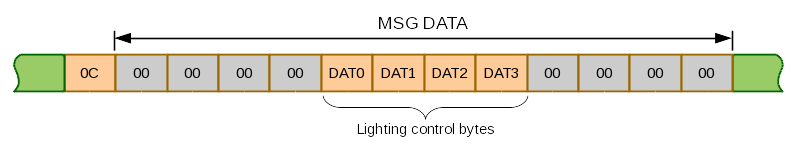
The sender of the message is diagnostics (identifier 3F ), recipient of LCM ( D0 ), message type 0C . In bytes DAT0 - DAT3 a mask is placed, where the correspondence of the bit to the external light fixture is determined. A single value in this mask causes current to be supplied to the corresponding device for 30 seconds, zero - immediately de-energize. In case of successful acceptance of the message from the diagnostics, LCM confirms with a positive acknowledgment: D0 03 3F A0 4C . Thus, the lighting device is turned on individually using the diagnostic equipment so that you can evaluate its performance. The table below shows the position of the DAT0-DAT3 bit, which will turn on the light for 30 seconds.
If it is necessary to include not one but several light devices, then it is enough to combine the value in the field DAT0-DAT3 by logical addition. This way you can make any available combination of lamps listed in the table shine. For example, if you send a message 3F 0F D0 0C 00 00 00 00 40 00 00 40 00 00 00 00 EC in I-bus, the left dipped beam headlamp and the front left turn signal will be turned on. Then, by message 3F 0F D0 0C 00 00 00 00 00 00 00 00 00 00 00 00 EC, redeem all.
Thanks to the described capabilities of LCM, you can create an application that can include any combination of light devices in a different sequence, limited only by the inertness of incandescent lamps. Obviously, the eLight module works this way. Colleagues from Germany took into account the possibilities of LCM and created their own project, which includes both hardware and software. The module itself is connected to the car simply, just 3 contacts: the case, the onboard power supply, I-bus. Then, using the application on the PC, the mode of the module is programmed. For example, when closing a car, the headlights turn on in such a sequence that they create the effect of running lights. A funny thing turns out. And what if you make light music from external lighting devices, which will be accompanied by sound from the car's sound system. It will be even more fun! Moreover, all the technical capabilities for this are there.
In the previous article, I already described the possibility of connecting to a standard speaker system as a CD changer. That is, with the sound output, everything is already clear. But how can you sync light with music? The obvious solution for me was using the MIDI protocol. Moreover, there is ready-made software that will allow you to create a light line synchronously with the music. I mean the sequencer.
MIDI is a musical instrument interaction protocol. The protocol is based on the serial transfer of data from the master device to the slave. As a master, there can be a MIDI keyboard or a sequencer, and as subordinates various synthesizers. MIDI protocol messages are divided into 2 types: channel messages and system messages. We are interested in channel messages, as the sound control commands are transmitted over them. Namely, those that contain information about the event with a note: the note is on, the note is off. This message also provides information on the strength of the impact on the note, but it is not of interest.
If we interpret the system of external light devices of the car as a subordinate MIDI device, where each lamp has its own note, then we get a “light synthesizer”. To him at least connect the sequencer, even the keyboard, and play with lights as you please. But for such an implementation, a process is needed that will convert the input MIDI stream into I-bus messages for LCM. In the figure below, this process is indicated by midi4lcm.
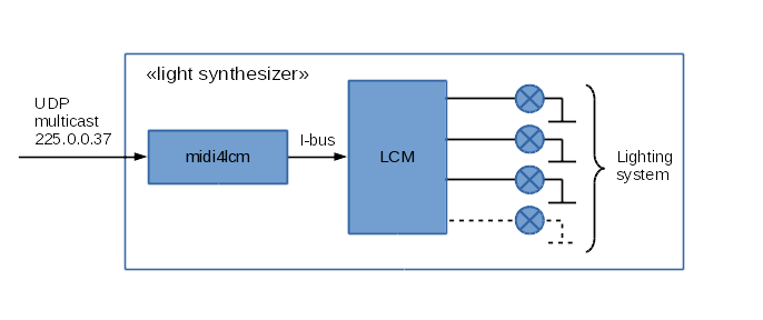
midi4lcm is a server that receives data on its network segment from multicast. Of the entire stream of received data, midi4lcm filters the voice MIDI messages of the 1st channel. Depending on what note was the impact, generates a message for LCM. MIDI messages are integrated taking into account a small delay, since each UDP datagram carrying information about a note event will form a separate I-bus message, which is too expensive. To do this, the server combines incoming MIDI messages into one I-bus message, if the reception interval does not exceed 1 ms.
In order to perform a light row on a car at a convenient time for us, you must have a saved sequence of MIDI messages, that is, a MIDI file. You can create it using sequencers. Today there is a large selection of applications for creating music and saving it in various formats. From the simplest sequencer to the clever music stations. In this embodiment, the main benefit of such applications is the ability to play a MIDI track and export it to a file. Especially if there is a possibility of parallel operation of the audio track, then it becomes possible to create a light series in synchronous sound. For example, how it looks in practice.
 .
.
Thus, the result of creativity for automotive light music is reduced to two files: MIDI and audio.
So, let's say we already have the necessary files for the MIDI light range and music, for example, in WAV format. You can synchronously reproduce them with the help of Gstreamer, if you have the necessary plug-ins. Namely by running the command line:
In this command, Gstreamer transmits MIDI messages from the lighting.mid file synchronously in accordance with the timestamps. Messages are transmitted to the ip address 127.0.0.1 and UDP port 21928. It is on this port that the midi4lcm server is configured to receive multicast. This is how MIDI devices working over a local network are usually configured. In addition to MIDI broadcasting, the gst-launch pipeline transfers the audio stream from the music.wav file to PulseAudio sound server. If the line output of the computer on which this command is executed is connected to the car's speaker system, then the desired effect will be achieved - the light music of the lighting devices to the soundtrack. True to the outside, this effect was “spectacular”, you must leave the door open, otherwise it will be too quiet.
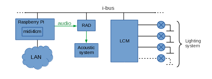
This figure shows the working scheme in more detail. The Raspberry Pi mini computer, which is integrated into the standard bus of interaction between the I-bus control units and the speaker system, serves as the vehicle's additional equipment. On the other hand, Raspberry has interfaces for connecting to a local network so that you can interact with other computers and receive audio and MIDI streams. In this case, it is possible to connect the sequencer to the car and check the operation of the MIDI track so to speak "live".
Lastly, I will show you how it turned out in practice:
.
Additional information on the topic:
" MIDI Wavy: make controlled color music with Arduino and MIDI
» A series of articles about MIDI from the magazine" Musical equipment "
»Dealer documentation for electrics of BMW“ BMW WDS ”cars
LCM (English Light Control Module) device that performs the following functionality:
- switching external and internal lighting devices;
- monitoring the health of incandescent bulbs;
- monitors the position of light switches;
- interaction with other control units.
Thus, LCM is a performer when the required lighting device is turned on. It receives control information from switches in the driver’s control zone or via the I-bus. As a feedback, information is provided to the bus about the devices turned on and their malfunction. Therefore, the driver will be promptly informed by a message on the dashboard, if, for example, the left low beam lamp has burned. Fault information is determined regardless of whether the device is turned on or not.
')
Lighting fixtures are switched by dc amplifiers on semiconductor devices. This eliminates the problems of burning contacts on the relay and the need to use fuses. However, it complicates the design and increases the cost of repairs. Cases when the output stages of the DC amplifiers fail are not rare. In this case, you have to repair the LCM or change it to serviceable and then encode it.
When installing an abnormal alarm, the master needs to get a contact to the wires of the turn signals or parking lights. They are usually tied up to a cable harness in the vicinity of the LCM unit. I saw this. Although the task could be solved more humanely by connecting to the I-bus through the microcontroller. In this case, abnormal alarms can access all lighting fixtures, not just turn signals. In addition, it will be available central locking, closer glasses, sunroof and folding mirrors. But the use of a microcontroller and the corresponding software is not an easy task, and the master will better ignore this option.
With dealer diagnostics and coding, you can interact with LCM. Read, clear trouble codes, query diagnostic commands, encode operation mode and parameters. Diagnostic equipment is connected to the D-bus, which does not have a physical connection to the LCM. LCM is an I-bus subscriber and interaction with diagnostic equipment takes place through a gateway in the dashboard. The gateway forwards messages from D-bus to I-bus and back. Thus, if you submit diagnostic requests to turn on a particular light device and “sniff” an I-bus, you can calculate the logic of the effect on the LCM registers to turn on the desired device. That's exactly what I did. On the BMW DIS running in the virtual machine, I asked the commands: turn on the left front turn signal, dipped right, left brake light, etc. At the same time, I fixed frames on the I-bus. The diagnostic request for the individual activation of the light device is as follows:
The sender of the message is diagnostics (identifier 3F ), recipient of LCM ( D0 ), message type 0C . In bytes DAT0 - DAT3 a mask is placed, where the correspondence of the bit to the external light fixture is determined. A single value in this mask causes current to be supplied to the corresponding device for 30 seconds, zero - immediately de-energize. In case of successful acceptance of the message from the diagnostics, LCM confirms with a positive acknowledgment: D0 03 3F A0 4C . Thus, the lighting device is turned on individually using the diagnostic equipment so that you can evaluate its performance. The table below shows the position of the DAT0-DAT3 bit, which will turn on the light for 30 seconds.
Show table
| | DAT0, bin | DAT1, bin | DAT2, bin | DAT3, bin | |--------------------------------------------------------------------------------------------| | | 00000000 | 00000000 | 00000000 | 00000001 | | | 00000000 | 00000000 | 00000000 | 00000010 | | | 00000000 | 00000000 | 00000000 | 00000100 | | | 00000000 | 00000000 | 00000000 | 00001000 | | | 00000000 | 00000000 | 00000000 | 00010000 | | | 00000000 | 00000000 | 00000000 | 00100000 | | | 00000000 | 00000000 | 00000000 | 01000000 | | | 00000000 | 00000000 | 00000000 | 10000000 | | | 00000000 | 00000000 | 00000001 | 00000000 | | | 00000000 | 00000000 | 00000010 | 00000000 | | | 00000000 | 00000000 | 00000100 | 00000000 | | | 00000000 | 00000000 | 00001000 | 00000000 | | - | 00000000 | 00000000 | 00010000 | 00000000 | | | 00000000 | 00000000 | 00100000 | 00000000 | | | 00000000 | 00000000 | 01000000 | 00000000 | | | 00000000 | 00000000 | 10000000 | 00000000 | | | 00000000 | 00000001 | 00000000 | 00000000 | | | 00000000 | 00000010 | 00000000 | 00000000 | | | 00000000 | 00000100 | 00000000 | 00000000 | | | 00000000 | 00001000 | 00000000 | 00000000 | | | 00000000 | 00010000 | 00000000 | 00000000 | | | 00000000 | 00100000 | 00000000 | 00000000 | | | 00000000 | 01000000 | 00000000 | 00000000 | | | 00000000 | 10000000 | 00000000 | 00000000 | | | 00000001 | 00000000 | 00000000 | 00000000 | | | 00000010 | 00000000 | 00000000 | 00000000 | | | 00000100 | 00000000 | 00000000 | 00000000 | | - | 00001000 | 00000000 | 00000000 | 00000000 | | - | 00010000 | 00000000 | 00000000 | 00000000 | | | 00100000 | 00000000 | 00000000 | 00000000 | | | 01000000 | 00000000 | 00000000 | 00000000 | | | 10000000 | 00000000 | 00000000 | 00000000 | If it is necessary to include not one but several light devices, then it is enough to combine the value in the field DAT0-DAT3 by logical addition. This way you can make any available combination of lamps listed in the table shine. For example, if you send a message 3F 0F D0 0C 00 00 00 00 40 00 00 40 00 00 00 00 EC in I-bus, the left dipped beam headlamp and the front left turn signal will be turned on. Then, by message 3F 0F D0 0C 00 00 00 00 00 00 00 00 00 00 00 00 EC, redeem all.
Thanks to the described capabilities of LCM, you can create an application that can include any combination of light devices in a different sequence, limited only by the inertness of incandescent lamps. Obviously, the eLight module works this way. Colleagues from Germany took into account the possibilities of LCM and created their own project, which includes both hardware and software. The module itself is connected to the car simply, just 3 contacts: the case, the onboard power supply, I-bus. Then, using the application on the PC, the mode of the module is programmed. For example, when closing a car, the headlights turn on in such a sequence that they create the effect of running lights. A funny thing turns out. And what if you make light music from external lighting devices, which will be accompanied by sound from the car's sound system. It will be even more fun! Moreover, all the technical capabilities for this are there.
In the previous article, I already described the possibility of connecting to a standard speaker system as a CD changer. That is, with the sound output, everything is already clear. But how can you sync light with music? The obvious solution for me was using the MIDI protocol. Moreover, there is ready-made software that will allow you to create a light line synchronously with the music. I mean the sequencer.
MIDI is a musical instrument interaction protocol. The protocol is based on the serial transfer of data from the master device to the slave. As a master, there can be a MIDI keyboard or a sequencer, and as subordinates various synthesizers. MIDI protocol messages are divided into 2 types: channel messages and system messages. We are interested in channel messages, as the sound control commands are transmitted over them. Namely, those that contain information about the event with a note: the note is on, the note is off. This message also provides information on the strength of the impact on the note, but it is not of interest.
If we interpret the system of external light devices of the car as a subordinate MIDI device, where each lamp has its own note, then we get a “light synthesizer”. To him at least connect the sequencer, even the keyboard, and play with lights as you please. But for such an implementation, a process is needed that will convert the input MIDI stream into I-bus messages for LCM. In the figure below, this process is indicated by midi4lcm.
midi4lcm is a server that receives data on its network segment from multicast. Of the entire stream of received data, midi4lcm filters the voice MIDI messages of the 1st channel. Depending on what note was the impact, generates a message for LCM. MIDI messages are integrated taking into account a small delay, since each UDP datagram carrying information about a note event will form a separate I-bus message, which is too expensive. To do this, the server combines incoming MIDI messages into one I-bus message, if the reception interval does not exceed 1 ms.
In order to perform a light row on a car at a convenient time for us, you must have a saved sequence of MIDI messages, that is, a MIDI file. You can create it using sequencers. Today there is a large selection of applications for creating music and saving it in various formats. From the simplest sequencer to the clever music stations. In this embodiment, the main benefit of such applications is the ability to play a MIDI track and export it to a file. Especially if there is a possibility of parallel operation of the audio track, then it becomes possible to create a light series in synchronous sound. For example, how it looks in practice.
Thus, the result of creativity for automotive light music is reduced to two files: MIDI and audio.
So, let's say we already have the necessary files for the MIDI light range and music, for example, in WAV format. You can synchronously reproduce them with the help of Gstreamer, if you have the necessary plug-ins. Namely by running the command line:
gst-launch-1.0 -v filesrc location=lighting.mid ! midiparse ! udpsink host=127.0.0.1 port=21928 sync=true filesrc location=music.wav ! wavparse ! pulsesink In this command, Gstreamer transmits MIDI messages from the lighting.mid file synchronously in accordance with the timestamps. Messages are transmitted to the ip address 127.0.0.1 and UDP port 21928. It is on this port that the midi4lcm server is configured to receive multicast. This is how MIDI devices working over a local network are usually configured. In addition to MIDI broadcasting, the gst-launch pipeline transfers the audio stream from the music.wav file to PulseAudio sound server. If the line output of the computer on which this command is executed is connected to the car's speaker system, then the desired effect will be achieved - the light music of the lighting devices to the soundtrack. True to the outside, this effect was “spectacular”, you must leave the door open, otherwise it will be too quiet.
This figure shows the working scheme in more detail. The Raspberry Pi mini computer, which is integrated into the standard bus of interaction between the I-bus control units and the speaker system, serves as the vehicle's additional equipment. On the other hand, Raspberry has interfaces for connecting to a local network so that you can interact with other computers and receive audio and MIDI streams. In this case, it is possible to connect the sequencer to the car and check the operation of the MIDI track so to speak "live".
Lastly, I will show you how it turned out in practice:
.
Additional information on the topic:
" MIDI Wavy: make controlled color music with Arduino and MIDI
» A series of articles about MIDI from the magazine" Musical equipment "
»Dealer documentation for electrics of BMW“ BMW WDS ”cars
Source: https://habr.com/ru/post/308170/
All Articles