Basics of computer networks. Subject number 2. Top level protocols
And hello again! Today we will talk about the top-level protocols. Let us examine how they work, what they consist of and where they are applied theoretically and in practice.

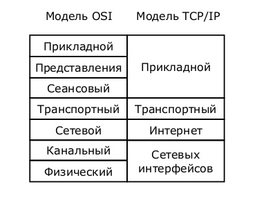
As you remember from the previous article (if not read, then the content has a link to it), the OSI model at the present time serves only as a training for the roles of each level. Networks work on a stack of TCP / IP protocols. Although TCP / IP consists of 4 levels, it fully implements all the functionality implemented in the OSI model. Below in the picture are comparisons of levels and their roles.
')
Let's start a conversation about top-level protocols. I did not just call the topic “Top Level Protocols”, and not “Top Level Protocols”. Since we parse this level of TCP / IP stack, then we have it "one for three."
In general, from the point of view of the networker, we do not care what happens inside the application layer. This is usually done by programmers. But it is important to know how data is formed and encapsulated into lower levels.
At work, for example, we have a rule: we ensure the launch of the application and its error-free transmission over the network. If the problem is internal software failures, then we switch to developers, and this becomes their concern. But there are also problems that go along the thin line between us, and we solve them together.
So, application layer protocols provide the interaction between a person and a network. There are a huge number of these protocols, and they perform completely different roles. I will give examples of frequently used protocols on the network and show how they work in practice: HTTP, DNS, DHCP, SMTP and POP3, Telnet, SSH, FTP, TFTP.
I) HTTP protocol (English HyperText Transport Protocol). A data transfer protocol commonly used to obtain information from websites. Every year this protocol is becoming more popular, and the possibilities for its use are becoming more and more. It uses the "client-server" model. That is, there are customers who form and send a request. And servers that listen to requests and, accordingly, respond to them.
The clients are well-known web browsers: Internet Explorer, Mozilla Firefox, Google Chrome, etc. And as server software use: Apache, IIS, nginx, etc.
In order to understand deeper into the HTTP protocol, take a look at the HTTP request from the client to the server.
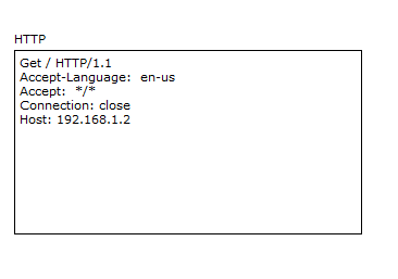
We are interested only in the top and bottom lines.
The first line uses such a thing as GET . This is essentially a request key. Since after the GET there is a symbol "/", it means that the main or root page is requested by the URL (English Uniform Resource Locator) of the path.
URL is a certain identifier of a resource in the network.
Also in this line there is a record such as HTTP / 1.1 . This is the protocol version. Pretty popular version. They released it in 1999, and still it serves faithfully. Although recently there was an announcement of version 2.0, version 1.1 is still in the lead.
Now about the bottom line. Here you can see the server address or the name where the required resource is located. Let's see how it works in practice. I will use my favorite program Cisco Packet Tracer 6.2 (hereinafter CPT). It is easy to learn and is ideal for demonstrating the above. I can say with confidence that in preparation for the CCNA R & S, it is quite enough. But only for her.
Open the program and add a computer with a server there (they are located on the “End Devices” tab), as in the picture below
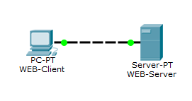
We connect the computer with the server with a cross cable (English crossover cable). In CPT, it is located on the “Connections” tab, indicated by a dotted line and called “Copper Cross-Over”.
Now let's set up a computer and a web server.
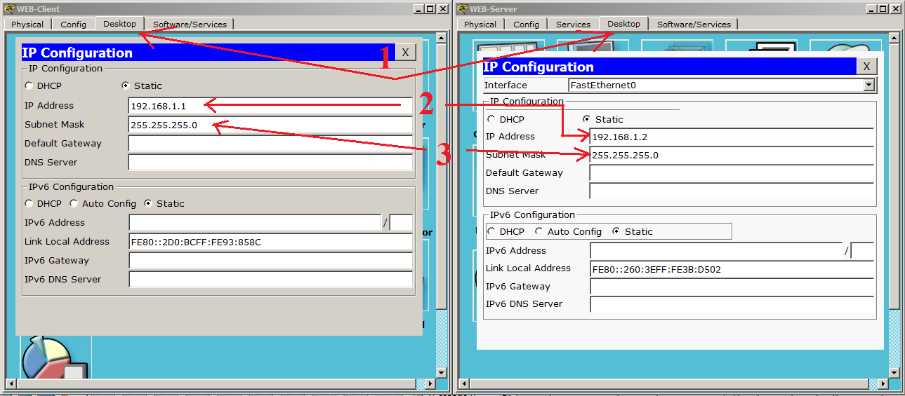
1) We tear off the “Desktop” tabs on the work computer and server, then go to the “IP Configuration” window. The windows will open, as in the image above. These are the configuration windows of the nodes in the network.
2) We specify the IP addresses in the lines indicated by the number 2. As we remember from the previous article, IP addresses are needed to identify the nodes in the network. We will discuss this topic in more detail later. Now the main thing is to understand why an IP address is needed. I specifically chose the network, starting with "192.168", as it occurs most often in home networks.
3) In the fields indicated by the digit 3, the subnet mask is entered. It is needed so that the host can understand whether it is on the same subnet with another host or not. But more about that later.
The remaining values are left blank.
Now you need to enable the HTTP service on the server.
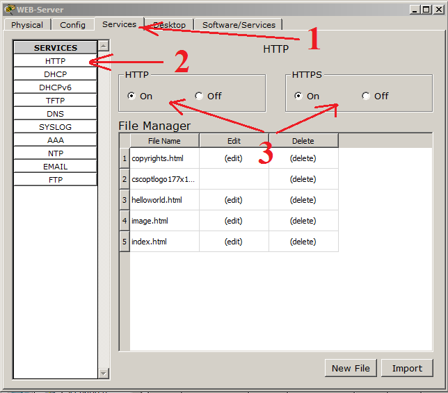
1) Go to the Services tab.
2) We select the HTTP service on the left.
3) The service settings window and file manager opens. If anyone has working skills with HTML, you can create a page here. But we already have a ready-made template, and we will use it. Do not forget to enable the HTTP and HTTPS service.
If we are already talking about HTTPS (HyperText Transfer Protocol Secure), I’ll say a few words about it. This is, in fact, an extension of the HTTP protocol, which supports cryptographic protocols and transmits information not encrypted, but encrypted. The CPT is very superficially shown his work, but for understanding is enough. We remember and remember: HTTP uses port 80, and HTTPS port 443. In general, there are a lot of port numbers, and everything is hard to remember, but often there are better to remember.
Now the fun part. We need to switch CPT from “Realtime” mode to “Simulation” mode. Their difference is that in the “Realtime” mode the network behaves as it would behave in real life and in real time. The “Simulation” mode allows us to observe the behavior of the network at different time intervals, as well as to track each packet, open it and see what it carries. Switch the environment, as shown in the figure below.
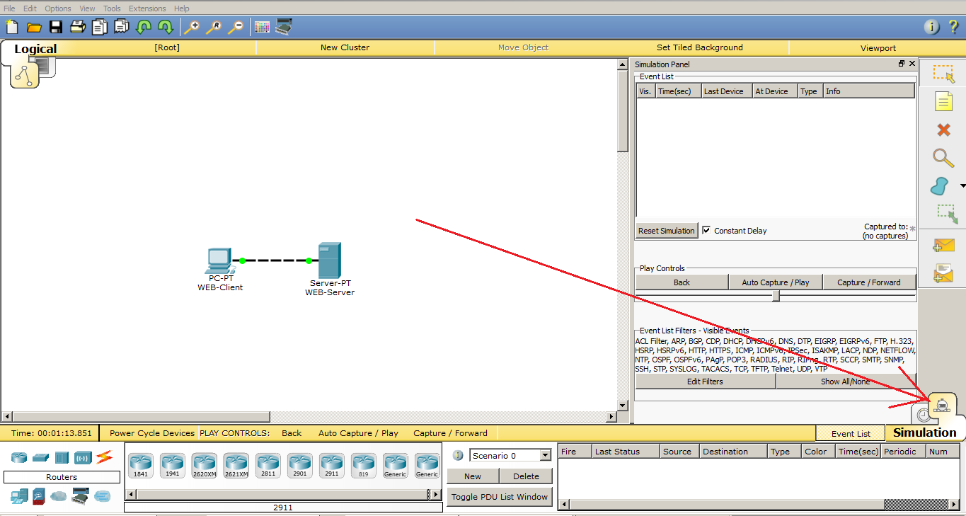
This is where the “Simulation Panel” opens, with several options. There is a filter in which you can specify the protocols that you want to monitor, the packet transfer speed and the navigation bar, where you can monitor the network manually, by clicking “Capture / Forward” or automatically, using the “Auto Capture / Play” button.
We leave everything as it is and open the computer.
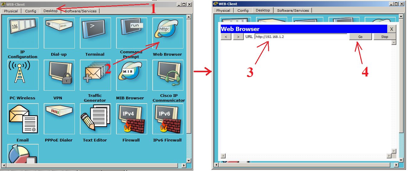
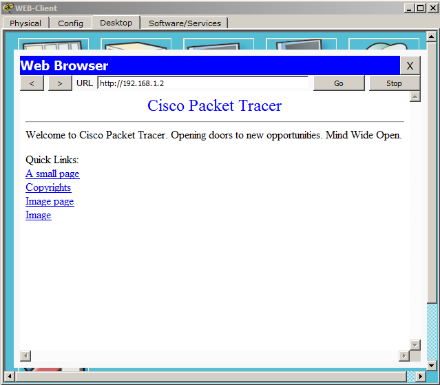
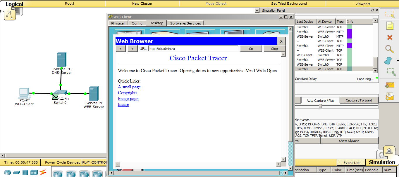
Go to the tab "Desktop" and open the "WEB Browser". A web browser window opens in front of us. In the URL line we write the address of our web server, click the “Go” button and observe the following picture.
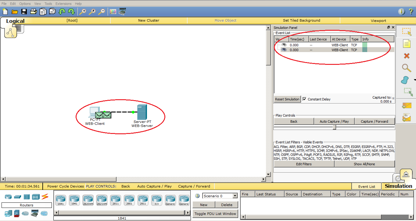
The first sent data appeared on the diagram and in the “Simulation Panel” window. These are the TCP segments that will create a session between the computer and the server. Now we are not interested, and we will talk about this in the next article. So I’ll skip them until the moment HTTP is created. I will do this with the “Capture / Forward” button.
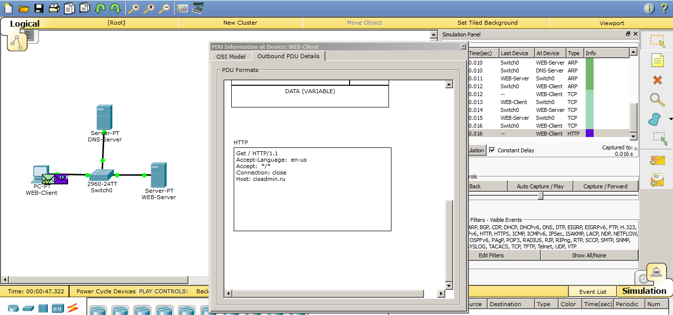
And after the connection is established, the computer generates the first HTTP data. In the following, I will call them PDUs so that you get used to these terms.
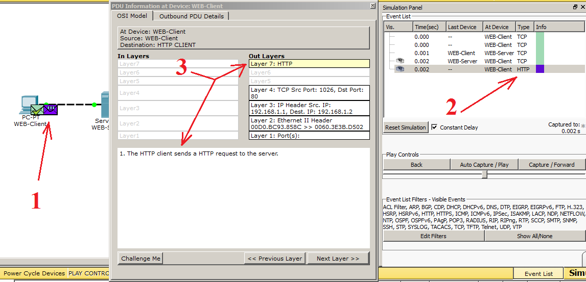
1) We look at the scheme and see that 2 envelopes have appeared. This is our data. We are interested in a purple envelope. This is the created PDU.
2) Now we look at the “Simulation Panel” and see that an entry with the HTTP type appears in the table. This data interests us. Also next to the record is the color with which these data are colored in the diagram.
3) Click on HTTP (purple envelope), and a data window opens before us. It briefly shows all the necessary information for each level of the OSI model. You can click on any level and get information about what is happening on it.
If it is interesting for you to fully disclose the data and consider in detail what fields they consist of and what is happening in them, there is an Outbound PDU Details tab. Let's move on to it and see what HTTP data looks like.
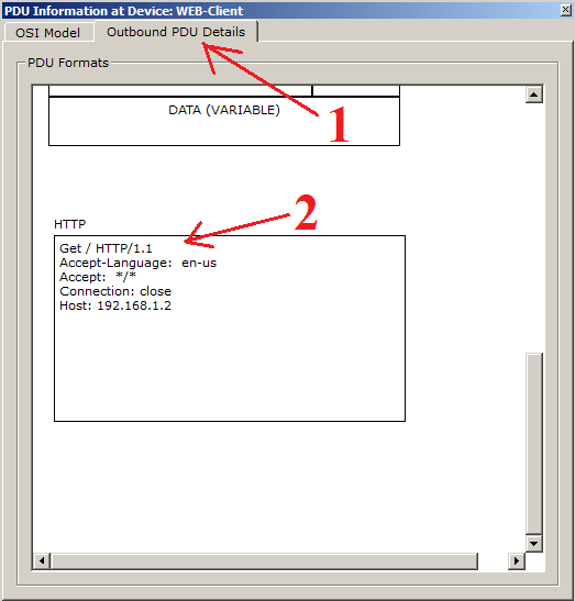
This tab will display data at all levels. We still need to look at HTTP. They are at the bottom, so pull the slider down. They look the same as I described them before.
Now we are interested in the stage when the web server receives the request and begins to take some action. Let's click on “Capture / Forward” and see how the web server responds. And so, in the figure below we see that he sent some data to the computer. Let's see what they look like.
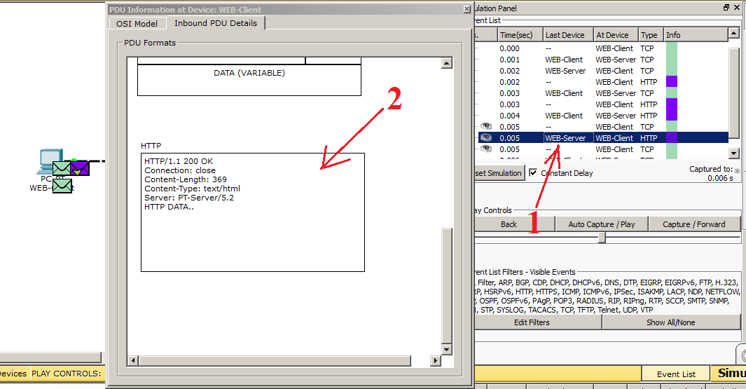
1) I accidentally squeezed the button and he already started to form TCP for closing the session Nothing wrong. Find the PDUs addressed from the web server to the client. As you can see, he immediately shows us on the diagram the point in time at which I clicked. Select the desired envelope.
2) Here we see another picture. The HTTP version is indicated above, the code “200 OK”, which means that the requested page is being sent, and not an error message. Next, indicate the length of the content, the file type, and from which server it is sent. And the bottom line indicates that some data is being transmitted. After the data reaches the computer, you can observe that the computer’s web browser has opened the page.
This is how HTTP works. Let's look at its extended version of HTTPS. As we remember, this version supports encryption and does not transmit data in the clear. At the very beginning, we enabled the HTTP and HTTPS service. Therefore, everything is ready, and you can request a page. The difference of the request is that before the address of the page instead of HTTP, we write HTTPS.
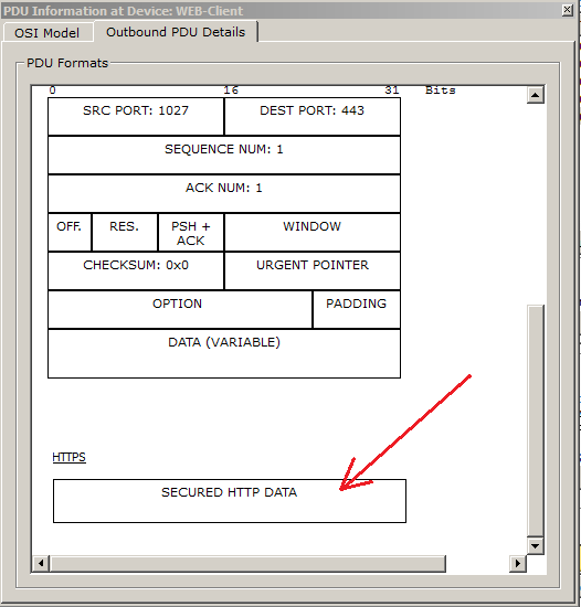
We see the inscription that the data is protected, and we cannot read it. In principle, these are all differences that CPT can show, but for a basic understanding this is enough. From myself I’ll add that when you go to the HTTPS website, it is indicated in the browser as a lock. for example
For those who want to pick it up and see how it works, you can download this lab here .
We talked about HTTP, and now it's time to parse the DNS protocol. This protocol is closely related to the previous protocol, and soon you will understand why.
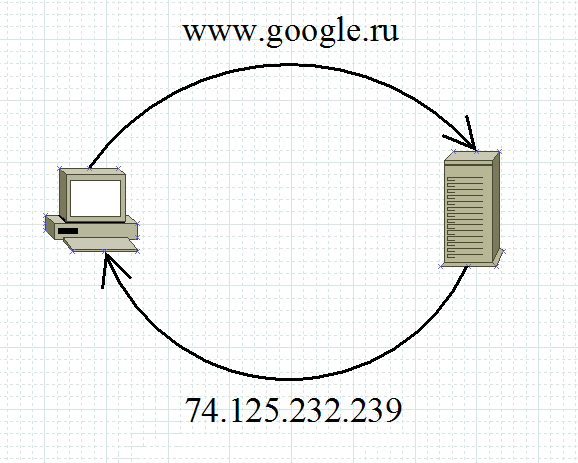
Ii) DNS (Domain Name System) . Domain Name System. Generally speaking, it stores information about domains. For example, which IP address corresponds to a specific name. I will give an example: when you open your favorite site, you refer to it by name. But in the Source Address and Destination Address fields that work at the network level (this is the topic of the next article, but I’ll run a little ahead), you cannot insert a name. There must necessarily be an IP address. This is what DNS is doing. It reports the IP address of the requested name. You, for example, are accessing google.com. Your computer has no idea who and what it is. He asks the DNS server: Who is google.com? And the server responds that google.ru is 74.125.232.239 (this is one of its addresses). And after that, the computer sends a request to 74.125.232.239. For the user, everything will remain the same, and in the address bar he will also see google.ru.
As usual, I'll show it in the picture.
I think that the above is understandable, and move on. This service is hierarchical. And often the DNS server (on which this service is running) works in conjunction with other DNS servers. Let's see what that means. Its hierarchy lies in the fact that it works with level domains. He works from junior to senior, from left to right.
For example the name: ru.wikipedia.org. The domain name “org” will be the eldest, and “ru” the youngest. But there are often cases when the DNS server cannot tell us about a domain name, and then it contacts the senior DNS server, which is responsible for the higher level domain names. I will not reinvent the wheel and bring a picture from Wikipedia. There, this work is illustrated well.
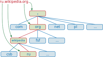
Suppose we typed in the browser address ru.wikipedia.org. The browser asks the DNS server: “what is the IP address of ru.wikipedia.org”? However, the DNS server may not know anything, not only about the requested name, but even about the entire wikipedia.org domain. In this case, the server accesses the root server — for example, 198.41.0.4. This server reports - "I do not have information about this address, but I know that 204.74.112.1 is responsible for the org zone." Then the DNS server sends its request to 204.74.112.1, but he answers, "I have no information about this server , but I know that 207.142.131.234 is responsible for the zone wikipedia.org. ”Finally, the same request is sent to the third DNS server and receives a response - the IP address, which is transmitted to the client browser.
I open CPT and show how it works. This and the following labs will be based on the previous one. Therefore, the addressing will be the same.
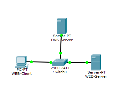
Here is added another server that will act as a DNS server and switch. When 3 or more devices appear on the network, a switch is used to connect them.
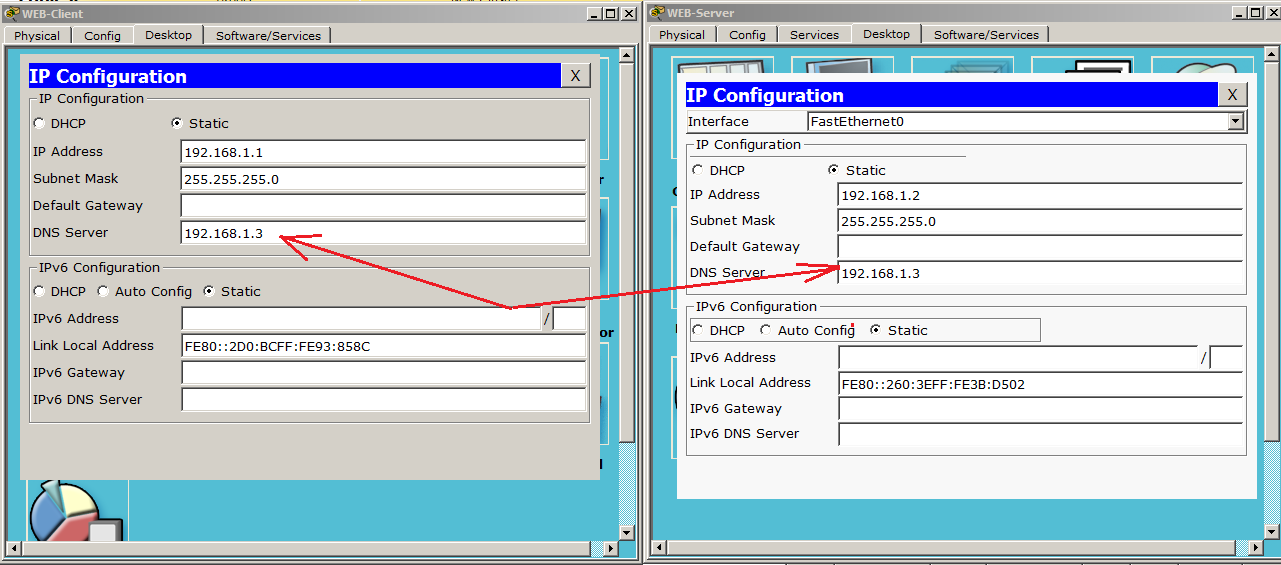
Let's do the configuration of the DNS server. Go to the "IP Configuration" and write down the IP address with a mask.

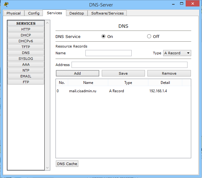
Now go to the services and configure the DNS service.
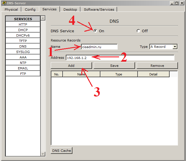
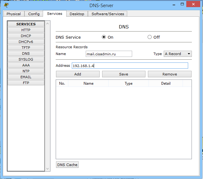
1) In the window "Name" write the name that we want to bind to the IP address. (I wrote the name of my future site, which is being worked on).
2) In the "Address" window, respectively, the IP address, which will work in conjunction with the above written name. (here we indicate the same address as in the laboratory on HTTP - 192.168.1.2).
3) Click the “Add” button to add this entry.
4) Do not forget to include the service itself!
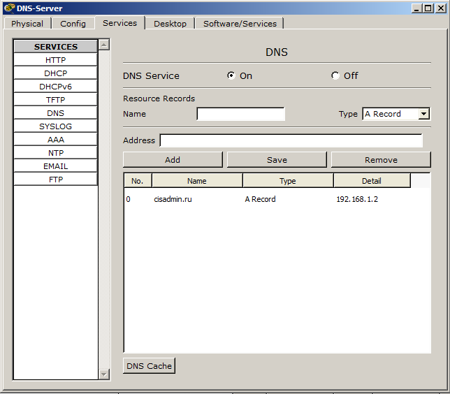
If everything is done correctly, then the picture should be like this.
Now you need to specify the address of the DNS server in the server and computer settings.
Configuring the DNS server and sites is complete, and it's time to check how this thing works. We switch the environment to the simulation mode and try to access the site from the computer called “cisadmin.ru”.
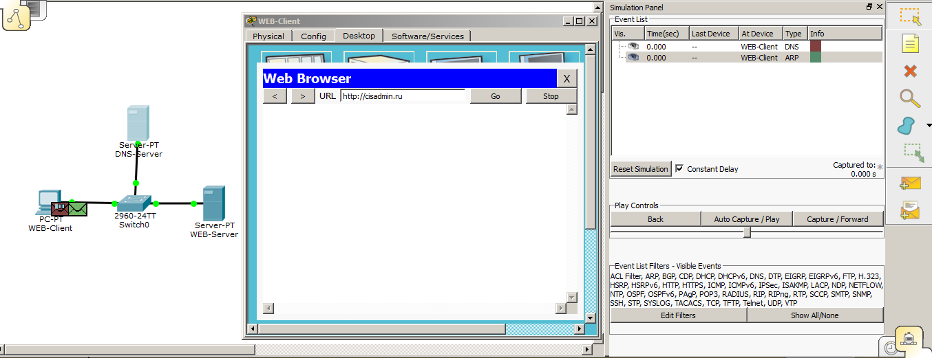
And we see that 2 envelopes are created. The first is DNS, and the second is ARP. We didn’t really talk about ARP, as this is the topic of the next article. But once he showed himself, then briefly tell you why. As we remember, there is not enough IP address for the exchange between the nodes, as the MAC addresses working on the data link layer are still used. We specified the IP address of the DNS server to the computer. But he does not know what the node with the IP address is 192.168.1.3. The MAC address. It generates an ARP message and throws it into the network. This frame (data on the data link layer is called frames) is broadcast, that is, it will be received by all participants on the same local network (all participants in the same broadcast domain are correct to say, but so far we have not affected this, and I will not load you with this term). And the one with this address will send a return message and report your MAC address. All other participants will drop this frame. Look at the pictures.
Here is the frame came to the switch, and now his task is to send this frame to all ports, in addition, where he came from.
Frames were sent and see the following. The frame that came to the web server was dropped, as indicated by the crossed-out envelope. Therefore, the frame is discarded. And the DNS server, on the contrary, found out its address and should form a response.
And as you can see, an ARP response was created. Let's break it down a bit.
1) MAC addresses. In the Source MAC, he writes his MAC address, and in the Destination MAC (Target MAC) the address of the computer.
2) In Source IP, your IP address, and in Target IP address of the PC.
I think everything is clear here. If it is not clear, ask. In the next article I will talk about it in more detail.
I click on “Capture / Forward” and see what happens next.
And I see that the computer has successfully received ARP from the server. Now he knows the MAC address of the DNS server, and therefore, how to contact him. And immediately decides to find out from him who this “cisadmin.ru” is. We can open this data and see what he decided to send there. Open "Outbound PDU Details" and go down to the bottom. We see that in the upper “NAME” field he recorded the requested name. Click the button “Capture / Forward” and look.
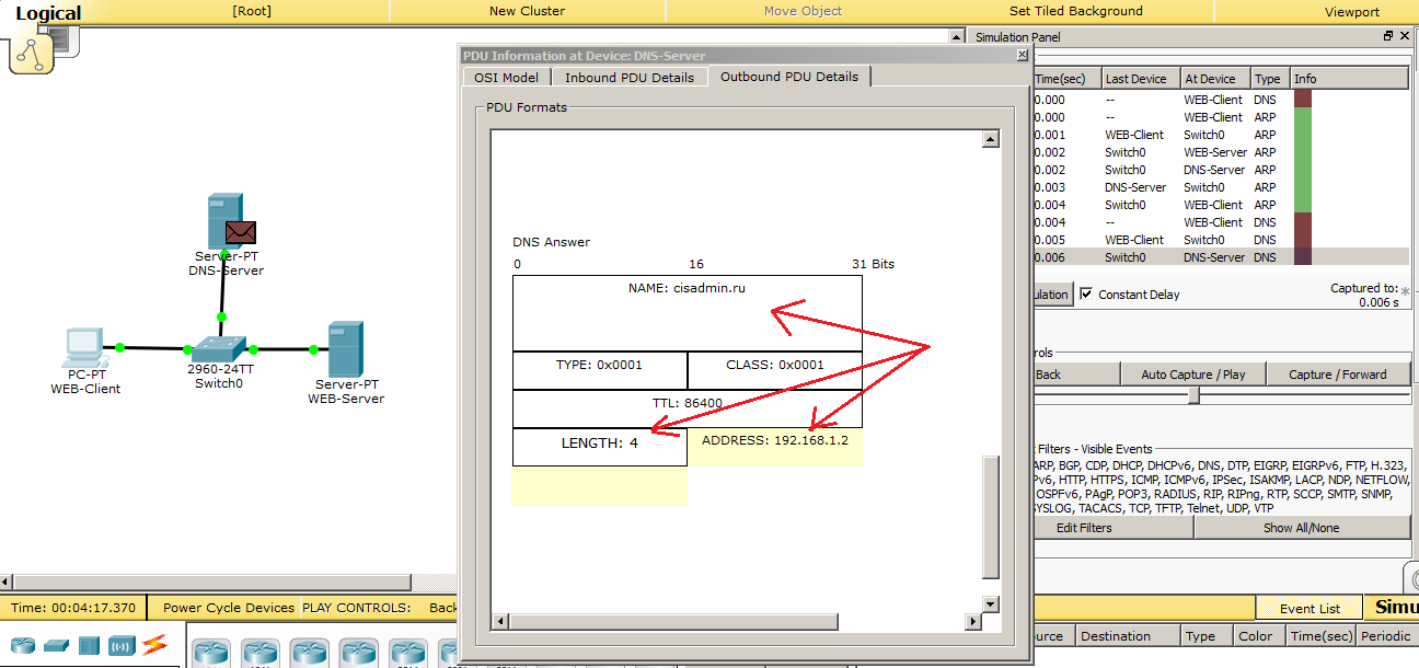
DNS server receives a DNS request. He climbs into his table and sees that he has such a record, and forms the answer. We open and see that the LENGTH field has changed and is equal to 4. That is, 4 bytes. So much is the IP address. And, accordingly, it records the IP address itself - 192.168.1.2. This is the web server address. Moving on.
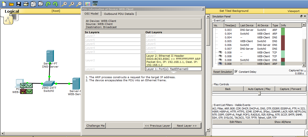
We see that the computer received a message from the DNS server, as indicated by a tick on the brown envelope. And now he knows the IP address of the web server. Immediately he tries to establish a TCP session, but a problem arises. He does not know the MAC address of the web server and runs a similar ARP request to find out. We look.
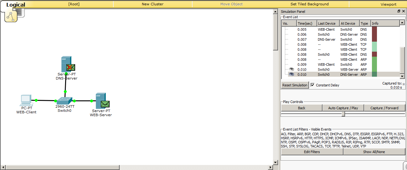
And here is similar to the previous one. The DNS server realized that the message was not for him, and discarded. And the web server finds out its IP address and generates an ARP response.
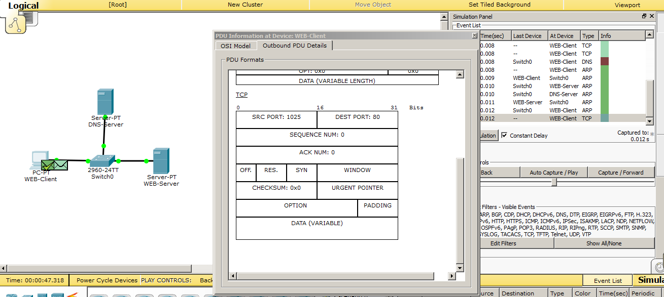
I got to the computer ARP answer. Now he knows the MAC address of the web server and tries to establish a TCP session. It sends a TCP segment to port 80. Since the TCP protocol has again made itself felt, and in the following protocols it will also appear, then I will briefly explain why it is needed. As you remember from the first article, I said that it establishes the connection. So now every data block that will be sent from the server to the computer will be marked. This is necessary in order for the client to understand whether all the data he received or some lost. And, if any data is lost, he will be able to request it again. Loss of a block of site data can lead to the fact that the site will skew, and it will appear crooked. But now the main thing is to understand that TCP is located at the transport level and works with ports. I specifically opened the window where it is written so that you gradually get used to these fields.
Let's see how the web server will respond to the computer.
The web server sends a response message to the computer and the session is established. And, when everything is ready, the computer generates HTTP and sends it to the web server. Let's see what has changed. And the last line has changed. If earlier there was recorded the IP address of the web server, now there is the domain name “cisadmin.ru”. But do not forget that the domain name here is written only in the application level data. The IP address has not gone away. It is located at the network level. So let's immediately show the IP packet where these addresses are presented.
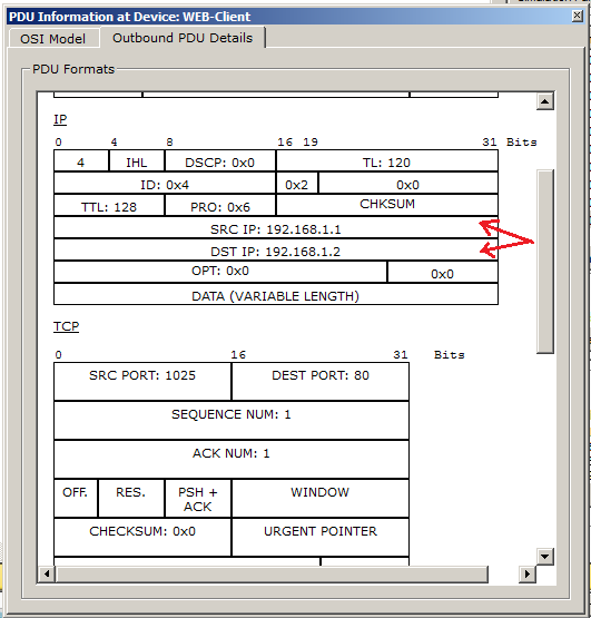
And as you can see, the IP addresses are in place.
Further, the process is similar to the laboratory for HTTP. Therefore, I will cite the final stage, where, by the name “cisadmin.ru”, a page will open that is located on the server with the IP address 192.168.1.2.
Accordingly, we see that everything works fine, and the site opens by a domain name.
And finally, I will mention one very important utility called nslookup . It allows you to contact the DNS server and find out the name or IP address information from it. In CPT, this command is present, and I suggest looking at it.
We click on the computer on the scheme and on the tab "Desktop" select "Command Prompt". This is an imitation of the command line.
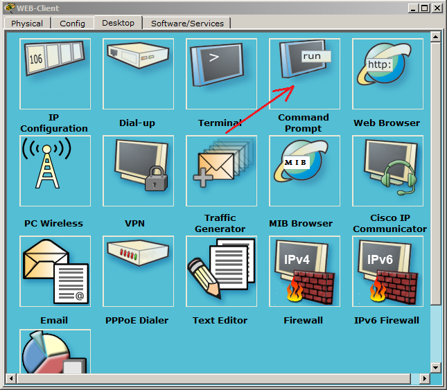
We open a window, like cmd in Windows. You can enter the "?" and press ENTER. It will show a list of all available commands. We need the nslookup command. Enter it and press ENTER.
The utility itself opens, as evidenced by the sign of the bird on the left. Shows us the address of the DNS server and its name. Since there is no name, it duplicates the line with the IP address.
Well, it's time to enter there the domain name and find out what it will give in response.

He gives the name and address, as expected. Basically, when you access a website, he performs this procedure himself. You have seen this query above.
There is another file in each OS that is closely related to DNS. His name is "hosts". Its standard location in Windows systems is "windows \ system32 \ drivers \ etc \ hosts". And in * nix similar systems: "/ etc / hosts". It does the same thing as the DNS server. And this file is controlled by the computer administrator. And the most important: it takes precedence over the DNS server. And, if you have written in the file that the website habrahabr.ru corresponds to the IP address, which actually corresponds to google.ru, then, accordingly, it will open google, not habrahabr. This is often used by attackers when they make corrections to this file. I will give a screen of this file from your computer.
This is how it looks. You can open it at home and realize that it is exactly the same.
Here is such an interesting service and protocol. Also as with HTTP, I will provide a link to download this labs.
And we move on and sort out the DHCP protocol.
Iii) DHCP (Dynamic Host Configuration Protocol). Dynamic Host Configuration Protocol It allows nodes to dynamically obtain IP addresses and other parameters for correct work on the network (main gateway, subnet mask, DNS server addresses). From myself I will say that this protocol saves the life of many sysadmins around the world. Agree that to go and manually register IP parameters for each node is not the most pleasant thing.
With DHCP, you can provide full control over IP addresses: create separate pools for each subnet, issue addresses for rent, reserve addresses and much more.
His work is very difficult for the current understanding. Too many packets, data and frames must be transmitted before the requested address is assigned to the computer.
Let's see how it works in practice.
And we see that a new server has been added. Of course, it was possible to give all the roles to one server, but in order for you to understand how the data goes, let there be a separate server for each role.
Set up the server.
We assign a free address and mask. Let us turn to the role of DHCP.
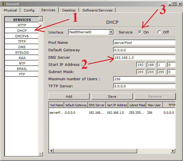
1) Select the DHCP service, and a standard pool has already been created here. It can not be deleted. Only change. You can create several pools yourself and do something with them, whatever, even delete. But the standard will always remain. We do not need additional pools, so we will redo the standard one.
2) Here you can add the gateway address, the DNS server address. We have not yet touched the question of the gateway, so for now we will not touch it. We have a DNS server, and you can specify it. Well, let's leave the start addresses as is.
3) Do not forget to turn on the server!
We switch the environment to the simulation mode and see how the computer gets the address.
Accordingly, go to the configuration settings and switch to DHCP.
We see that a DHCP request has been created. Let's go through each drop and superficially see what's inside.
1) Data link layer protocol (Ethernet). The address of the computer is recorded in the “Source MAC”. And in the “Destination MAC” is recorded the broadcast address (that is, all).
2) Network layer protocol (IP). The address “0.0.0.0” is recorded in the “Source IP”. This address is inserted when the requested address does not have an address. And in the "Destination IP" is inserted the broadcast address "255.255.255.255".
We look further.
Let's look at the UDP field. Ports 67 and 68 are used here. These are UDP ports reserved for DHCP.
Now we look at the DHCP field. Here, everything is zero, and only in the “CLIENT HARDWARE ADDRESS” field is the MAC address of the computer.
We know how the broadcast works, and see how the network members will react to it.
And we see that all but the DHCP server have dropped the data.
Then I will tell you how the protocol works in words, because a lot of packets and frames will be formed before the DHCP server issues an address. As soon as he receives a request, he begins to look for a free address in the database. As soon as the address is found, the next stage begins - this is the verification of the address. After all, as we remember, the address can be assigned manually, bypassing the DHCP server. This often happens, and even in the corporate environment there are clever people who manually enter the address. For this, the DHCP server sends an ICMP message or ping before issuing this address.
We have not talked about this yet. Therefore, I will say in advance that the ping utility allows you to check the availability of a node by its IP address. And, if someone answers a ping to the DHCP server, then the address is busy and it will repeat the whole procedure, but with a different IP address. But this is also not the most sensible decision. You understand that if a computer with a statically assigned address is turned off, it will not respond to the ping of the DHCP server, and, accordingly, DHCP will decide that the address is not busy and assign it to some node. But, as soon as the computer turns on, 2 computers with the same IP addresses will appear. And then wild miracles can begin. Modern systems have already learned how to respond to this correctly, but still it is not necessary to allow this and it is important to monitor this. I’ll skip all this data in CPT, otherwise I’ll make a filmstrip of monotonous pictures. I will attach this lab belowand you can see for yourself. I will give only the final result, which will form a DHCP-server.
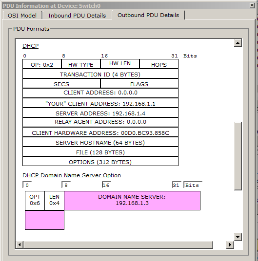
And we see that in the field “YOUR” CLIENT ADDRESS ”the address 192.168.1.1 was added. This is the address that the DHCP server offers to the computer. In the "SERVER ADDRESS" field, the DHCP server adds its address so that the computer knows who offers it the address. In the "CLIENT HARDWARE ADDRESS" field, the MAC address of the computer (that is, the one who requested) is added. And at the very bottom is the option "DHCP Domain Name Server Option". This is the address of the DNS server, which we specified in the DHCP service settings.
Let's see how the computer gets the address.
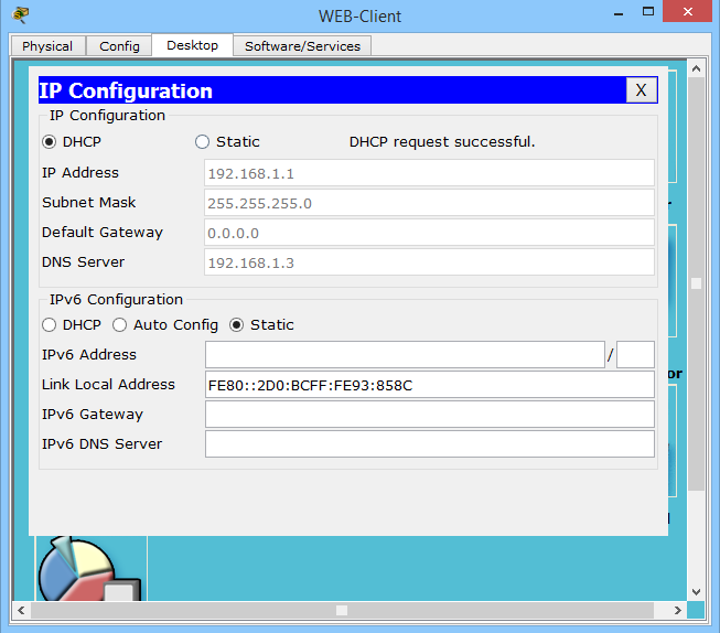
And we observe the message “DHCP Request Successful”. Which means that the data was successfully received, as evidenced by the completed fields below.
This is how DHCP works. As promised, download link .
Moving on, and the turn came to the protocols POP3 and SMTP. I specifically mentioned these protocols together and now I will explain why.
IV) POP3 (English Post Office Protocol Version 3). Post Office Protocol Version 3. The protocol that clients use to receive mail from the server. Versions 1st and 2nd are outdated and are not used at the present time. It works on the principle of "download and delete." What does it mean?This means that the client enters the server and looks to see if there is a letter for it. And if it is present, it loads it to itself and puts a mark about deletion on the server. Good or bad, a moot point. Someone claims that this is good, since the server is not overloaded with unnecessary letters. I think otherwise. Firstly, the modern infrastructure allows you to store a large amount of letters, and secondly, it often happens that the user deletes or loses an important letter, and then it becomes difficult to find it. Although it is worth mentioning that some clients can be configured so that they do not delete letters from the server. However, with standard settings, they delete emails from the server. Therefore, be careful. The port that he is listening on is 110. A fairly well-known port number, so take notes. Just like the HTTP protocol,He has an enhanced version - POP3S. With the help of an additional cryptographic protocol, like SSL, the contents are encrypted, and the letters are transmitted securely. POP3S uses port 995. We will definitely consider the POP3 protocol in practice, after we learn about the SMTP protocol.
It is worth mentioning about the analogue of POP3. This is the IMAP protocol (Internet Message Access Protocol). Email Access Protocol. It is more intelligent and more complex than POP3. But their main difference is that the client, entering the server, does not delete the mail, but copies it. Thus, the client displays a copy of the mailbox, which is stored on the mail server. And if the client removes any letter from himself, then it is deleted only from him. On the server, the original remains whole. He listens to port 143. It is not possible to consider IMAP in detail in CPT, since it is not fully implemented there.
V) SMTP (English Simple Mail Transfer Protocol).Simple mail transfer protocol. It is used, as you understand, to transfer mail to the mail server. That is why we study POP3 and SMTP in parallel. It uses port 25. This is also important to remember.
It is also important to remember that all mail protocols work over a TCP connection. That is, with the establishment of the connection. Here it is important to get every package safe and sound.
I think from a theoretical point of view, everything is clear. Let's move on to practice and see how it works.
I will open the previous laboratory work on DHCP and slightly upgrade it.
I removed the HTTP server and added a desktop computer instead, and called WORKER-PC. I will assign him the IP address that the HTTP server had. That is, 192.168.1.2. Old computer renamed DIRECTOR-PC. I left the DNS server. We still need it in this lab. DHCP server renamed to Mail-Server. And let's set it up.
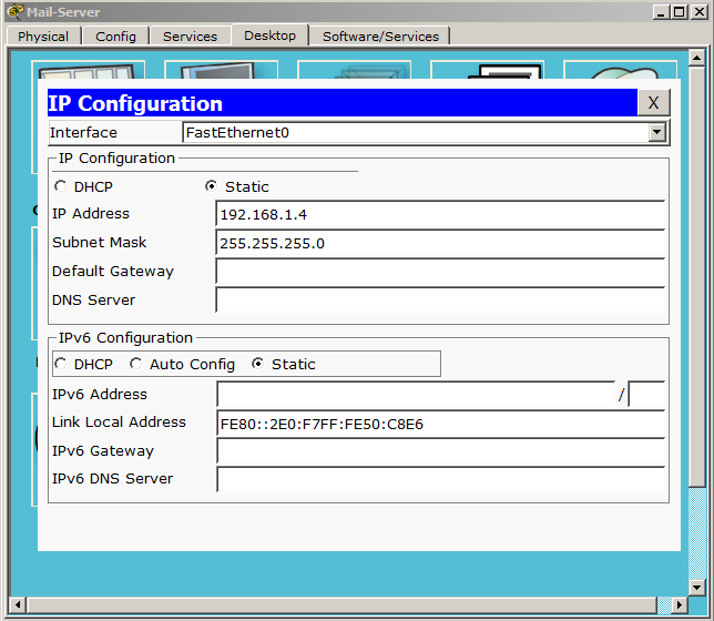
I did not change the address, and he remained from the last labs. Let it remain so. Go to the service and find the "EMAIL".
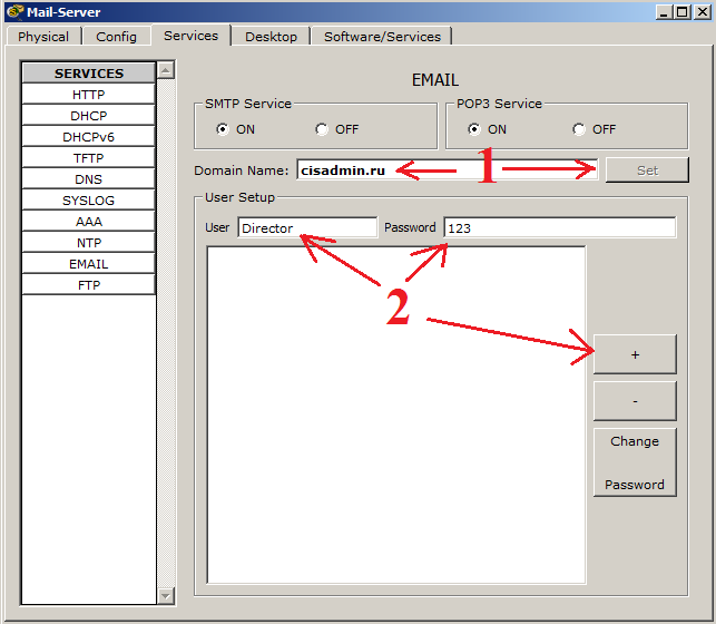
1) In the field "Domain Name" you must write the domain name. This is what will be written after the "@" sign. Mandatory requirement. Any mail is written in this format - login @ domain. And press the "Set" button. I have already pressed it, so it is not active, but if you make changes to the domain name entry field, it will become active again.
2) And create users. In the field "User" we will write the first user. This will be the "Director". And set the password "123". And click on the "+" sign to add it to the database. Similarly, create a second user. This will be “Worker” with the same password “123”.
The creation of users is complete, and we observe the following picture.
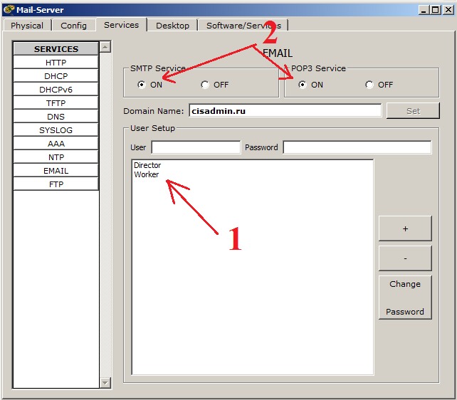
1) We see in the database a list of created users. They can be removed, added and changed passwords using the buttons on the right.
2) Do not forget to enable POP3 and SMTP services. They are enabled by default, but verification will not be superfluous.
This completes the server-side configuration, and now we’ll proceed to the client-side configuration. Let's start with the director's computer. Open the "Desktop" tab and select Email.
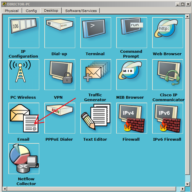
After that, the settings window will immediately open.

1) In the field “Your Name” we write any name. I will write Director.
2) In the field "Email Address" we write a mailbox. For the director, this is director@cisadmin.ru.
3) In the "Incoming Mail Server" and "Outgoing Mail Server" fields, write the address of the mail server (192.168.1.4)
4) In the field “User Name” we write the login itself. That is, Director and, accordingly, the password 123.
Press the "Save" button, and we open a mail client. CPT called it an email browser.

The same setting will be on the desktop computer. I bring a screen.

Now it's time to see how mail works. Let's first take a look at how it works in real time, and then we will take a closer look at the simulation mode.
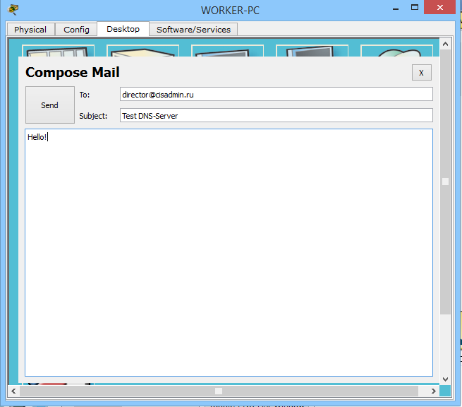
Open the mail client on the director's computer and create a letter.

Click on the button “Compose”, and a familiar window opens before us.
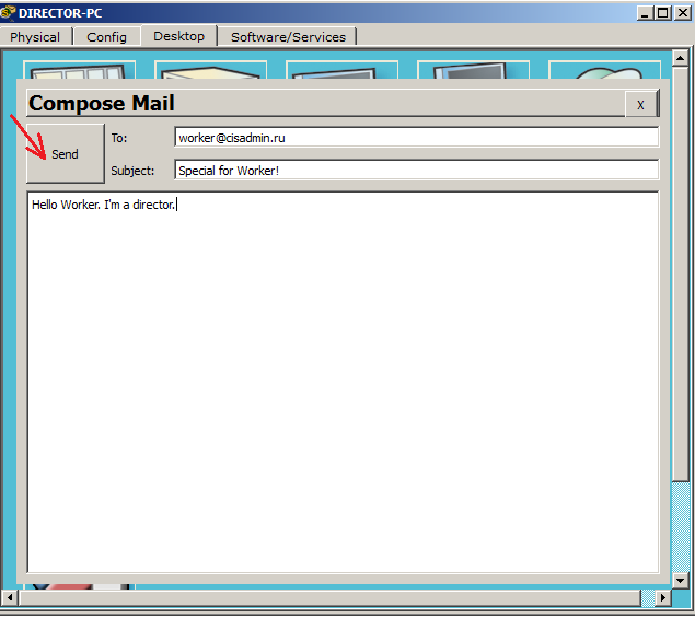
Everything is as usual here. We write to whom we send, the subject of the letter, the text of the letter itself and press the button “Send”.

We see the following message that the sending was completed successfully. Wonderful! Now let's see how the letter will be delivered to the worker.
Open the mail client on the desktop computer.

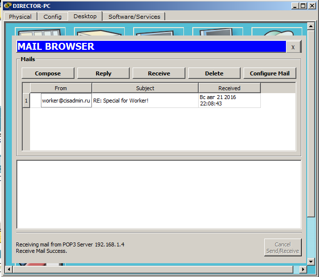
And we see that there is no letter. And all because the client in the CPT does not support automatic updating and you have to do it manually. Push the "Receive" button.
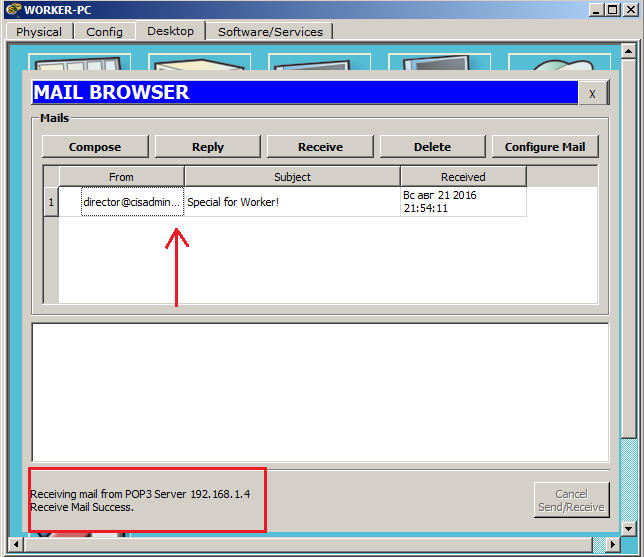
We see the appeared letter and the message on successful receipt. Let's open the letter and see if it’s broken.
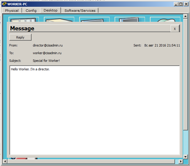
And yes, the letter, indeed, came unharmed. We will answer this letter and at the same time check that the letters go both ways. I click the "Reply" button and write the answer.
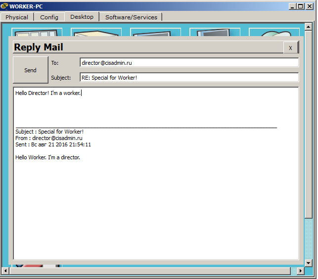
I send the letter and go to the director's computer. And, accordingly, press the “Receive” button to update the mail.
There was a letter, and below, and a message about the successful receipt.
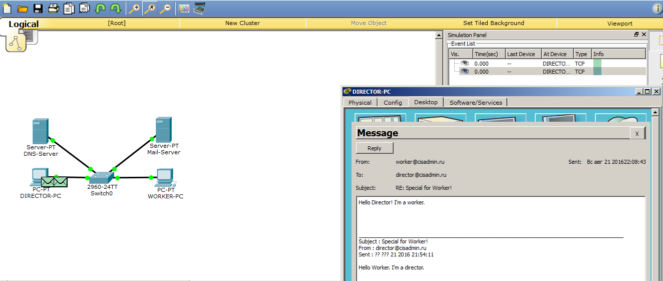
Open the letter to make sure to the end.

The letter reached, which means everything works.
Let's take a closer look. Switch the environment to simulation mode and send an email. I will not create something new, but just answer the above received letter.
As I said earlier, all mail protocols work with TCP. And this means that before the mail protocol starts to work, and in this case the SMTP protocol, a preliminary connection should be established between the computer and the server. This is what we are seeing now.
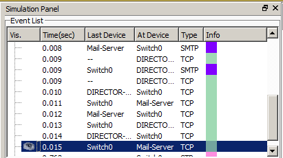
Now the process of establishing a connection interests us a little. We are now talking about mail protocols, and therefore I will skip this process and wait for the appearance of SMTP.

1) The long-awaited SMTP appeared, as indicated by the entry in the simulation panel, and open them. Pay attention to TCP ports to make sure that this is it. And we see that in the "Destination Port" is 25 number. And in the “Source Port” a dynamically invented port is recorded so that the server can identify the client. All right
2) We look at the SMTP data below, and there is nothing interesting here. CPT shows us like a normal data block.
Then he sends this data to the server. Let's see what happens next.

The server, receiving data from the computer, generates a response message. Pay attention to the changes. The numbers that were present were swapped, namely the “Source Port” and “Destination Port”. Now the source is the server, and the destination is the computer. This is a message about the delivery of letters to the server.
After that, the SMTP protocol operation is over, and the computer can start to close the TCP session. What he will do.
Now that the letter has been sent, and we know that it is on the server, we will try to receive this letter. Open the desktop computer and click the button "Receive".
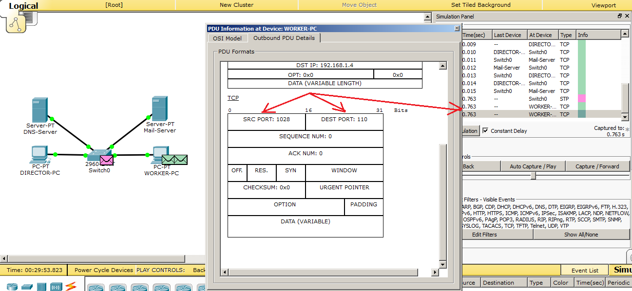
As with SMTP, a TCP session is also created in POP3. Let's look at the port numbers. The “Destination Port” is 110 port number. This is the standard port number for POP3. The “Source Port” is port 1028.
We look further and wait for the release of POP3.
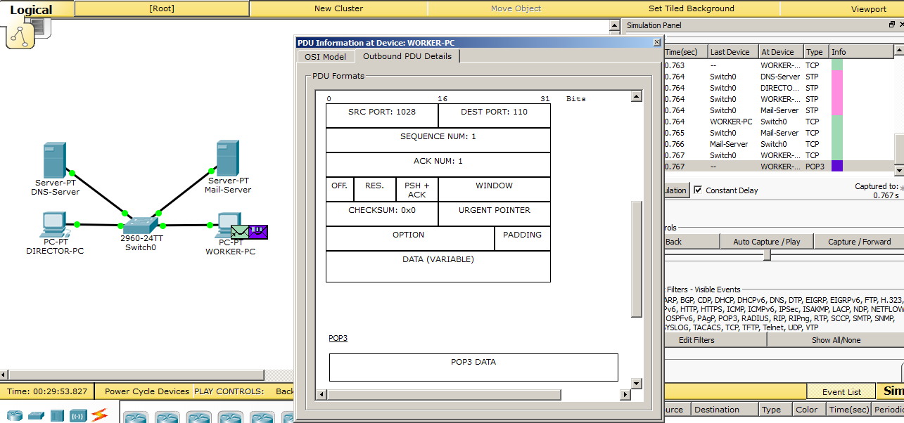
Here he appeared and observed that in the POP3 field the same picture as in SMTP, i.e. all that and so it was clear.
Then he sends this request to the server, and the server must respond with a letter if it is there.
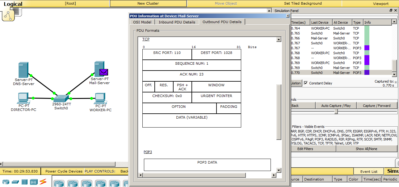
We know that it is there and observe how the server generates a response message. And just like with SMTP, it reverses the ports of departure and destination. At the application level, some POP3 data is packed. This is the letter itself.
As soon as the data gets to the computer, they should immediately be displayed in the mail client.
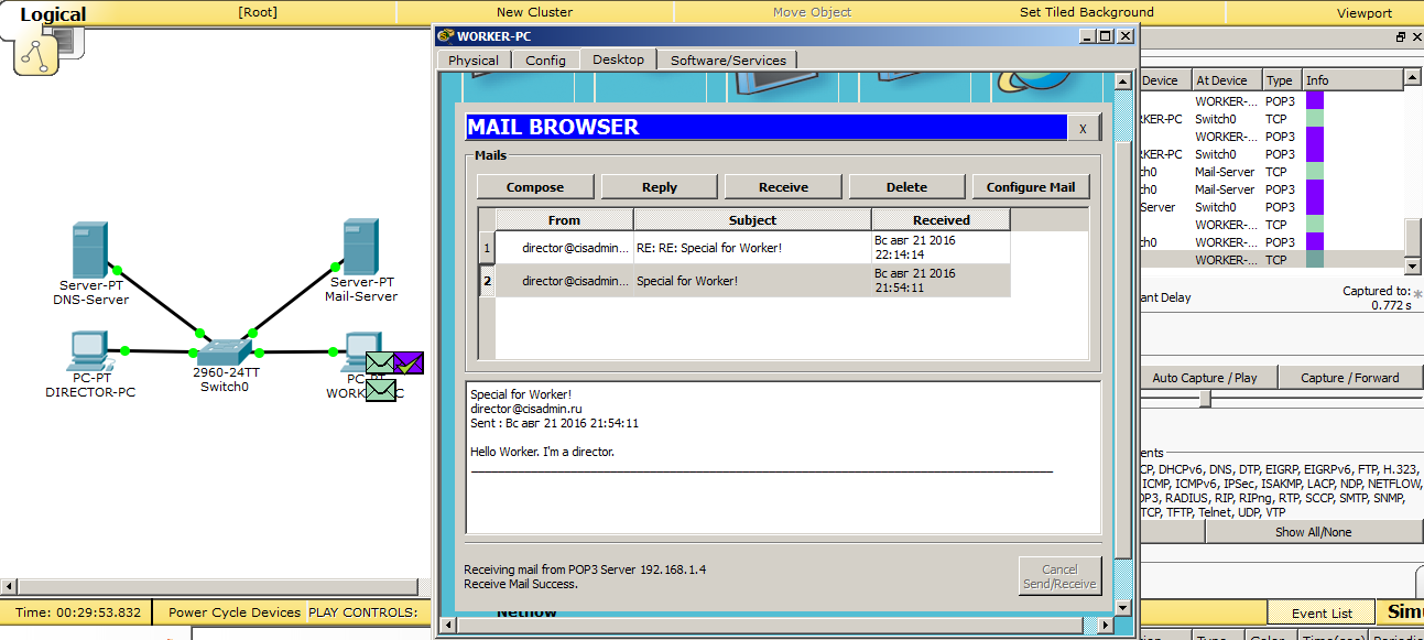
And as soon as the data is received, as indicated here by the check mark on the purple package, the letter is immediately displayed in the client. Further, as in SMTP, will be the closure of the TCP session.
I give a link to download this labs.
And another thing that I would like to show in addition to email protocols is the role of the DNS server. You have seen that when performing any action in the mail client, he wrote to us at the bottom of the server’s IP address. But it is possible to specify not an IP address, but a domain name. Let's see how to do this.
Well, the most logical thing that comes to mind is that we have a mail server with the address 192.168.1.4. And with this address we will have a domain name. Accordingly, we go to the DNS server and match the name to this address.
The configuration on the side of the DNS server is completed, and it remains to change 2 lines in the mail clients of computers. We open the client on the director's computer.

And click on the button "Configure Mail".
The window that we saw during the initial configuration of the client opens.

Here you need to change the lines "Incoming Mail Server" and "Outgoing Mail Server". Instead of the IP address, we write down the domain name and click the “Save” button.
The same is done on the worker’s computer. I will not give extra details, just give a screen.

Immediately try to write a letter to the director and send.
And after clicking the "Send" button, we observe the following.
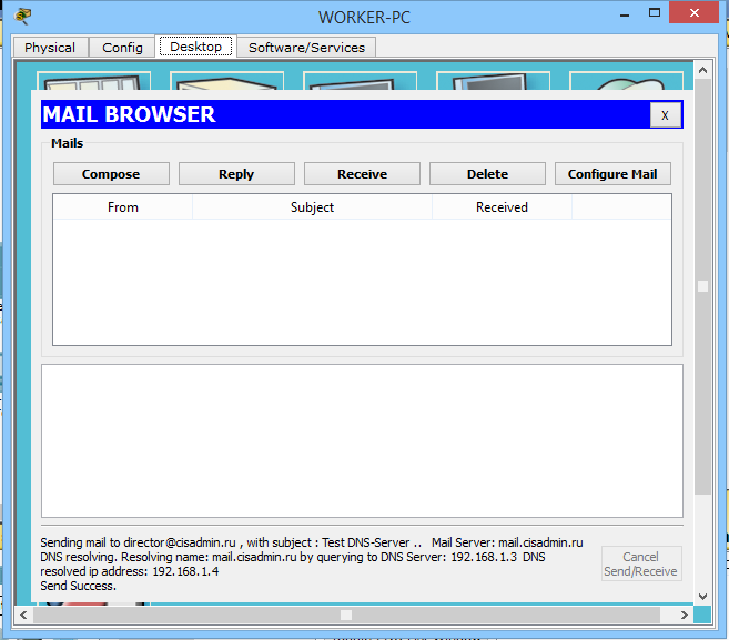
At the bottom there is a message that he asked the DNS server for the address, and he gave him the IP address of the mail server. Sending was successful.
Now let's go to the director’s computer and click on the “Receive” button.

We receive a letter, and the inscription below indicates successful delivery. Here is another example of using a DNS server on a network.
We have disassembled mail protocols. And proceed to the analysis of the next protocol.
VI) Telnet (from the English. Terminal network). If you translate literally, then this is a network terminal. The foundations of this protocol were laid a long time ago, and so far it has not lost its relevance. It is used to display the text interface, as well as to control the OS. A very useful protocol, and every network engineer must know how to work with it. I will explain why. Each network device, the interface of which is a command line, is configured either using a special console cable or through virtual terminals, which includes the Telnet protocol. And, if the console cable requires a specialist to be located next to the equipment to be configured, then tuning using virtual terminals, and in this case Telnet, does not limit the specialist in distance. You can be in another room, building, city and still have the opportunity to access equipment. I think this is a huge plus. From the minuses of this protocol, I note that it is actually not protected and everything is transmitted in the clear. It uses port 23. And the most popular distributions that work with this protocol are Putty, Kitty, XShell, etc. I think we will consolidate his work in practice.
We will use Telnet to access the Cisco 2960 switch. It, like all Cisco devices, uses the Cisco IOS operating system. And the command line interface is called CLI (Command Line Interface). Let's first set up the switch. We will hang the IP address on it, because without it we will not be able to get to the switch and allow access via Telnet. I will not give screenshots, as there are no graphics. Just give a list of input commands and explain what they are for.
Switch> enable - switch to privileged mode. From here, most teams are available.
Switch # configure terminal - switch to global configuration mode. In this mode, you can enter
commands that allow you to configure general system characteristics. From global configuration mode, you can switch to a variety of configuration modes that are specific to
specific protocol or function.
Switch (config) #username admin secret cisco - create a user with the username admin and the password cisco.
Switch (config) #interface vlan 1 - go to the virtual interface and hang the IP address on it. Here the beauty lies in the fact that it does not matter on which of the 24 ports it will hang. The main thing for us is to have access to it from any port.
Switch (config-if) #ip address 192.168.1.254 255.255.255.0 - assign the last address 192.168.1.254 with the mask 255.255.255.0
Switch (config-if) #no shutdown - the interface is turned off by default, so we turn it on. In IOS, 90% of commands are canceled or disabled by assignment before the “no” command.
Switch (config) #line vty 0 15 - go to the settings of virtual lines where Telnet lives. From 0 to 15 means that we apply this to all lines. You can install up to 16 simultaneous connections on it.
Switch (config-line) #transport input all - and allow the connection for all protocols. I specifically set up for all protocols, since a bit later another protocol will be considered and I do not consider it reasonable to climb here for the sake of one team.
Switch (config-line) #login local - we specify that the account is local, and it will check it with the one we created.
Switch # copy running-config startup-config - be sure to save the configuration. Otherwise, after resetting the switch, everything will reset.
So the switch is configured. Let's connect to it from the work computer. Open the command prompt. We opened it when we looked at nslookup. And we write the following.
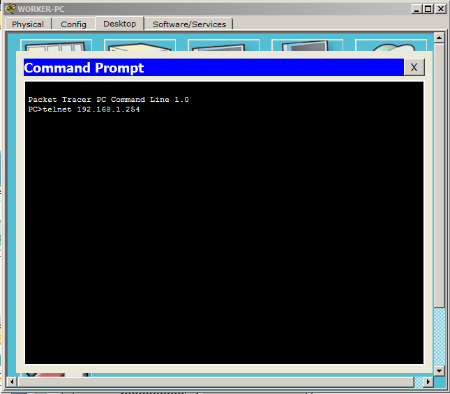
That is the telnet command and the address where to connect.
If everything is correct, the next window opens with a request for a login and password.

Accordingly, we write login: admin and password: cisco (we created it on the switch).
And he immediately lets us on the switch. To check, check the availability of the director's computer, using the ping command.

Ping is successful. I hope it is clear that the availability check is performed not from the worker’s computer, but from the switch. The computer here is the control device and that's it. I will not consider it in simulation mode. It works in the same way as mail protocols, that is, a TCP session is created, and after the connection is established, Telnet begins to work. As soon as he fulfills, he begins to break the connection. It's simple. I give a link to download.
Let's now break down the SSH protocol.
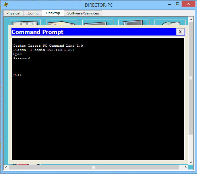
VII) SSH (English Secure Shell). Translated from English - a safe shell. Like telnet allows you to manage the OS. Its difference is that it encrypts all traffic and transmitted passwords. Encrypted using the Diffie-Hellman algorithm . Who cares read. Almost all modern OS systems are able to work with this protocol. If you have a choice of which protocol to use, then use SSH. First, you will suffer a little in tuning, and much will not be clear, but it will settle down in time with your head. The main thing to remember now is that the most important difference between SSH and Telnet is that SSH encrypts traffic, but Telnet does not. I think it's time to go to practice and see how it works. We will connect and manage the same switch. Let's try to connect via SSH from the director's computer to the switch.

Here, the command syntax is slightly different than when connected via Telnet. We write ssh with the key l, after we type the login (we have this admin) and the address where we connect (192.168.1.254). Finish this case with the ENTER key. A message is displayed that the connection was closed by an external host. That is, the switch has closed the connection. That's because the keys that work with encryption were not created. I’ll go to the switch and configure it to work properly over SSH.
Switch (config) #hostname SW1 - change the name of the switch. With this standard name, you cannot register a domain that is needed for generating keys.
SW1 (config) #ip domain-name cisadmin.ru - register domain.
SW1 (config) #crypto key generate rsa - generate RSA keys.
The keys for the keys will be: SW1.cisadmin.ru
Choose the size of the modulus in the range of 360 to 2048 for your
General Purpose Keys. Choosing a key modulus greater than 512 may take
a few minutes.
How many bits in the modulus [512]: 1024 - Specify the key size. The default is 512, but I will enter 1024.
% Generating 1024 bit RSA keys, keys will be non-exportable ... [OK]
There is a message about the successful generation of keys.
Setup is complete, and try again to connect to the switch.
And another message is already displayed, asking for a password. Enter the password "cisco" and find ourselves on the switch.
It remains to check the work. I will use the ping command and check the availability of the work computer.

And made sure that everything works fine. I bring the link to make sure you.
And I turn to the next protocol.
VIII) FTP (English File Transfer Protocol). File Transfer Protocol. I think from the name of the protocol it is clear that it transfers files. A very ancient protocol, released in the early 70s. It appeared before HTTP and the TCP / IP stack. As he worked before, he still works according to the “client-server” model. That is, there is the initiator of the connection and the one who listens to it. There are several modifications that support encryption, tunneling, and so on. Previously, different console utilities worked with this protocol, which did not have graphics and they worked by entering certain commands. At the present time there are also graphic programs. The most popular and simple is Filezilla. In CPT, only the console method is implemented.
We proceed to practice. As a basis, I will take the previous lab and replace the mail server with an FTP server.
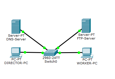
In principle, the scheme is similar to the previous one.
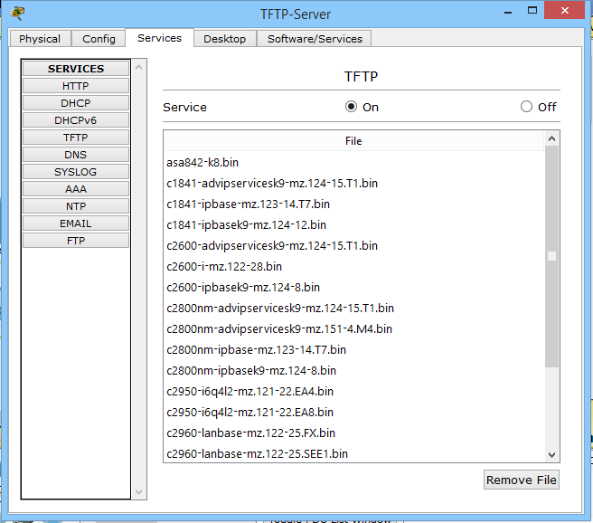
Open the FTP server and go to the FTP service.

By default, the service is enabled, but it is better to check.
1) I marked 1 in account, which was created by default here. This is a standard account with the login "cisco" and the same password. In the right column we see "Permission" - this is access rights. And we see that this account has all the rights. In the test environment, this is exactly what we need, but when working in a company, always follow the rights of each account.
2) Digit 2 marked FTP repository. Here are mostly firmware for cisc devices.
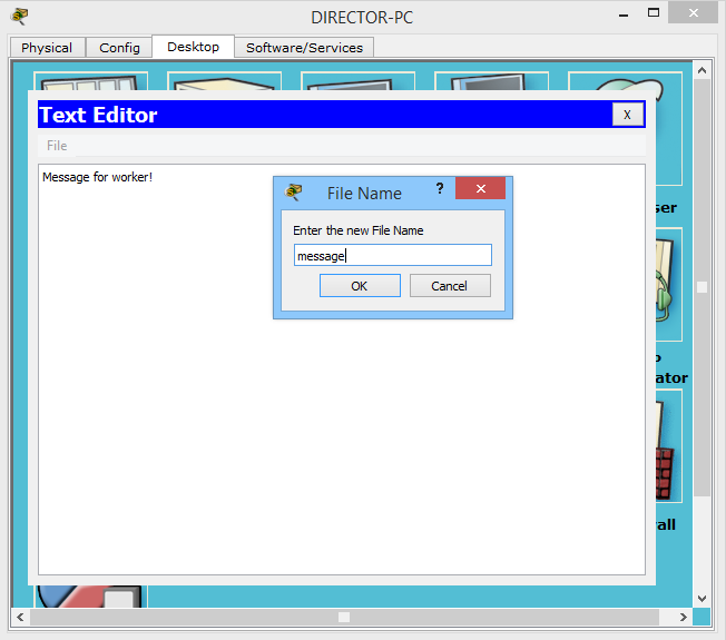
The service is set up and once everything is so beautiful, we will try to work with it. But first, let's create a text file on the director’s computer, which I then download to the FTP server.
I open the director's computer and select "Text Editor". This is an analog notebook in Windows.

I will write there the text and save it.
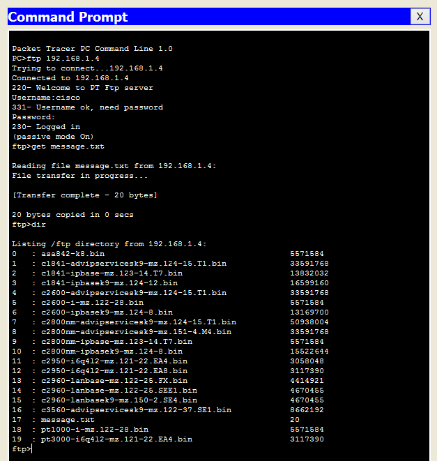
Now we will try to upload this file to an FTP server. Open the command line and write

That is, as we remember earlier, the protocol used is written at the beginning, and then the address follows. Next, after the connection, the login is asked (we enter cisco) and the password (also cisco). And after authentication we get to the FTP server itself. The list of available commands can be checked with the "?" Command.
To upload something, use the “put” command, and download the “get” command. Fill our file.
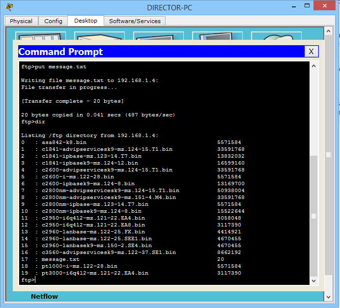
I entered the “put” command and the name of the file I want to copy. And he shows us a message that everything is copied. The file weighs 20 bytes, and the transfer rate is 487 bytes per second. Then I entered the “dir” command to check the contents of the server. And the message.txt file was lit up with the 17th number.
It remains the case for small. This is a download file on the desktop computer. I open WORKER-PC and enter the command line.
I perform almost the same actions as before. Except for the “get” command, not “put”. We see that the file is downloaded. I also entered the "dir" command to show that when downloading a file, the original is not deleted. Download a copy of it.
And once he downloaded the file, it should appear on the computer. I open the “Text Editor” and click File-> Open.

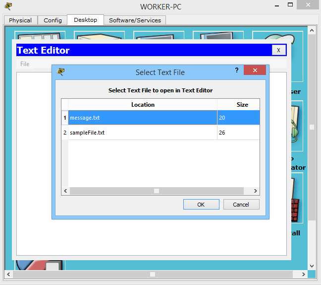
I see that the file is really present and try to open it.

The file came intact. All text is present.
I will not re-clog your head, how it works. Because it works in the same way as mail protocols, Telnet, SSH, and so on. That is, a TCP session is created, and the file transfer / download begins. I will give only the structure of it.
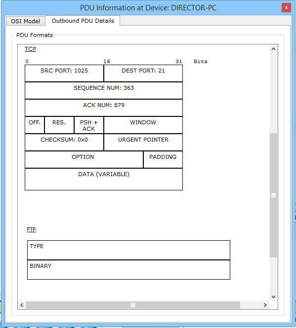
In TCP we pay attention to the port number. This is port 21 (standard FTP port). And in the FTP data field it is indicated that it is some kind of binary data.
This is how the world famous protocol works. More advanced versions are not supported here, but they work in almost the same way. Here is a link to the lab.
And the last protocol that remains is TFTP.
IX) TFTP (English Trivial File Transfer Protocol). Simple file transfer protocol. Invented it in the 80s.Although FTP was quite popular, not all its functions were needed for simple tasks. And a simple analogue was invented. It works via UDP, that is, it does not require connection establishment. Also, it does not require authentication and authorization. It is enough to know its IP address and have it yourself. This is certainly not safe, since the address can be faked. But when a simple protocol is needed and authorization is not required, the choice falls on it. The tsiskov equipment works very closely with it to copy the image or download it to flash-memory.
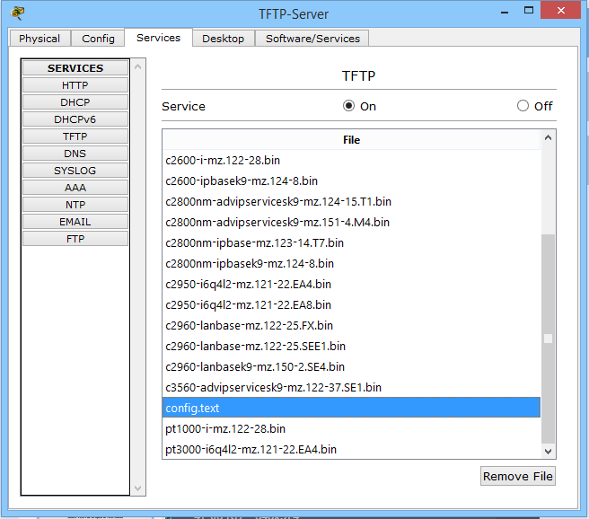
Nothing teaches better than practice. Therefore, go to her. Miraculously, I discovered that computers in CPT do not know how to work with TFTP. It is good that they did not cut out this function from the tsiskov equipment. Therefore, we will learn from our favorite switch. The scheme remains the same. Just on the FTP server, I will enable the TFTP service.
This is how it looks. The database has a bunch of different firmware for many devices.
Let's go to the switch.
SW1 # dir - command for outputting the contents of the file system
Directory of flash: /
1 -rw- 4414921 c2960-lanbase-mz.122-25.FX.bin
9 -rw- 1168 config.text
64016384 bytes total (59600295 bytes free)
We have There is a file config.text. Let's try to upload it to the TFTP server.
SW1 # copy flash: tftp: - that is, we specify from where, and then where. Here it is from flash-memory on tftp-server
Source filename []? config.text - here it asks for the name of the file to be copied.
Address or name of remote host []? 192.168.1.4 - specify where to copy.
Destination filename [config.text]? - and here you need to specify under what name to save it on the server. By default, it offers to save it with the same name. And if you press the ENTER key, it will select the default name. It suits me, and I will leave it the same.
Writing config.text .... !!!
[OK - 1168 bytes]
1168 bytes copied in 3.048 secs (383 bytes / sec)
And in the final message it shows that everything copied successfully. Let's go to the TFTP server and check.
And I see that he is really there. So the switch did not deceive me.
Now we will try to download something from the server to the switch.
SW1 # copy tftp: flash: - here we write the opposite. First tftp, and then flash
Address or name of remote host []? 192.168.1.4 - TFTP-server address
Next, he will ask what to copy. I do not remember the exact name of the firmware and open TFTP to view.

Write down the name
Source filename []? c2960-lanbasek9-mz.150-2.SE4.bin
Destination filename [c2960-lanbasek9-mz.150-2.SE4.bin]? - here he asks what to call it on the switch itself. I'll press ENTER and leave the default name.
Accessing tftp: //192.168.1.4/c2960-lanbasek9-mz.150-2.SE4.bin ...
Loading c2960-lanbasek9-mz.150-2.SE4.bin from 192.168.1.4: !!!
[OK - 4670455 bytes]
4670455 bytes copied in 0.057 secs (6587503 bytes / sec)
He gave me a message that the download was successful. I check the availability of the firmware with the command "dir".
SW1 # dir
Directory of flash: /
1 -rw- 4414921 c2960-lanbase-mz.122-25.FX.bin
10 -rw- 4670455 c2960-lanbasek9-mz.150-2.SE4.bin
9 -rw- 1168 config.text
64016384 bytes total (54929840 bytes free)
I see that everything is really in place. And in addition, he tells me about the amount of memory and the availability of free space.
We finished to consider top-level protocols. I did not think that it would be such a long article. Perhaps the blame pictures. But I tried as briefly as possible in the case. We considered a lot of protocols, and all of them are irreplaceable. Often help out the life of the sysadmin and our favorite users. Thank you for reading. If something is not clear, leave comments or immediately write in a personal. And I went to put the kettle and drink delicious tea with cakes!
Content
1) Basic network terms, OSI network model and TCP / IP protocol stack.
2) Top-level protocols.
3) Protocols of lower levels (transport, network and channel).
4) Network devices and types of cables used.
5) The concept of IP addressing, subnet masks and their calculation.
6) The concept of VLAN, Trunk and VTP and DTP protocols.
7) Spanning Tree Protocol: STP.
8) Channel Aggregation Protocol: Etherchannel.
9) Routing: static and dynamic on the example of RIP, OSPF and EIGRP.
10) Network Address Translation: NAT and PAT.
11) Reservation protocols for the first transition: FHRP.
12) Computer network security and virtual private networks: VPN.
13) Global networks and protocols used: PPP, HDLC, Frame Relay.
14) Introduction to IPv6 configuration and routing.
15) Network management and network monitoring.
PS Perhaps over time, the list will be added.
As you remember from the previous article (if not read, then the content has a link to it), the OSI model at the present time serves only as a training for the roles of each level. Networks work on a stack of TCP / IP protocols. Although TCP / IP consists of 4 levels, it fully implements all the functionality implemented in the OSI model. Below in the picture are comparisons of levels and their roles.
')
Let's start a conversation about top-level protocols. I did not just call the topic “Top Level Protocols”, and not “Top Level Protocols”. Since we parse this level of TCP / IP stack, then we have it "one for three."
In general, from the point of view of the networker, we do not care what happens inside the application layer. This is usually done by programmers. But it is important to know how data is formed and encapsulated into lower levels.
At work, for example, we have a rule: we ensure the launch of the application and its error-free transmission over the network. If the problem is internal software failures, then we switch to developers, and this becomes their concern. But there are also problems that go along the thin line between us, and we solve them together.
So, application layer protocols provide the interaction between a person and a network. There are a huge number of these protocols, and they perform completely different roles. I will give examples of frequently used protocols on the network and show how they work in practice: HTTP, DNS, DHCP, SMTP and POP3, Telnet, SSH, FTP, TFTP.
I) HTTP protocol (English HyperText Transport Protocol). A data transfer protocol commonly used to obtain information from websites. Every year this protocol is becoming more popular, and the possibilities for its use are becoming more and more. It uses the "client-server" model. That is, there are customers who form and send a request. And servers that listen to requests and, accordingly, respond to them.
The clients are well-known web browsers: Internet Explorer, Mozilla Firefox, Google Chrome, etc. And as server software use: Apache, IIS, nginx, etc.
In order to understand deeper into the HTTP protocol, take a look at the HTTP request from the client to the server.
We are interested only in the top and bottom lines.
The first line uses such a thing as GET . This is essentially a request key. Since after the GET there is a symbol "/", it means that the main or root page is requested by the URL (English Uniform Resource Locator) of the path.
URL is a certain identifier of a resource in the network.
Also in this line there is a record such as HTTP / 1.1 . This is the protocol version. Pretty popular version. They released it in 1999, and still it serves faithfully. Although recently there was an announcement of version 2.0, version 1.1 is still in the lead.
Now about the bottom line. Here you can see the server address or the name where the required resource is located. Let's see how it works in practice. I will use my favorite program Cisco Packet Tracer 6.2 (hereinafter CPT). It is easy to learn and is ideal for demonstrating the above. I can say with confidence that in preparation for the CCNA R & S, it is quite enough. But only for her.
Open the program and add a computer with a server there (they are located on the “End Devices” tab), as in the picture below
We connect the computer with the server with a cross cable (English crossover cable). In CPT, it is located on the “Connections” tab, indicated by a dotted line and called “Copper Cross-Over”.
Now let's set up a computer and a web server.
1) We tear off the “Desktop” tabs on the work computer and server, then go to the “IP Configuration” window. The windows will open, as in the image above. These are the configuration windows of the nodes in the network.
2) We specify the IP addresses in the lines indicated by the number 2. As we remember from the previous article, IP addresses are needed to identify the nodes in the network. We will discuss this topic in more detail later. Now the main thing is to understand why an IP address is needed. I specifically chose the network, starting with "192.168", as it occurs most often in home networks.
3) In the fields indicated by the digit 3, the subnet mask is entered. It is needed so that the host can understand whether it is on the same subnet with another host or not. But more about that later.
The remaining values are left blank.
Now you need to enable the HTTP service on the server.
1) Go to the Services tab.
2) We select the HTTP service on the left.
3) The service settings window and file manager opens. If anyone has working skills with HTML, you can create a page here. But we already have a ready-made template, and we will use it. Do not forget to enable the HTTP and HTTPS service.
If we are already talking about HTTPS (HyperText Transfer Protocol Secure), I’ll say a few words about it. This is, in fact, an extension of the HTTP protocol, which supports cryptographic protocols and transmits information not encrypted, but encrypted. The CPT is very superficially shown his work, but for understanding is enough. We remember and remember: HTTP uses port 80, and HTTPS port 443. In general, there are a lot of port numbers, and everything is hard to remember, but often there are better to remember.
Now the fun part. We need to switch CPT from “Realtime” mode to “Simulation” mode. Their difference is that in the “Realtime” mode the network behaves as it would behave in real life and in real time. The “Simulation” mode allows us to observe the behavior of the network at different time intervals, as well as to track each packet, open it and see what it carries. Switch the environment, as shown in the figure below.
This is where the “Simulation Panel” opens, with several options. There is a filter in which you can specify the protocols that you want to monitor, the packet transfer speed and the navigation bar, where you can monitor the network manually, by clicking “Capture / Forward” or automatically, using the “Auto Capture / Play” button.
We leave everything as it is and open the computer.
Go to the tab "Desktop" and open the "WEB Browser". A web browser window opens in front of us. In the URL line we write the address of our web server, click the “Go” button and observe the following picture.
The first sent data appeared on the diagram and in the “Simulation Panel” window. These are the TCP segments that will create a session between the computer and the server. Now we are not interested, and we will talk about this in the next article. So I’ll skip them until the moment HTTP is created. I will do this with the “Capture / Forward” button.
And after the connection is established, the computer generates the first HTTP data. In the following, I will call them PDUs so that you get used to these terms.
1) We look at the scheme and see that 2 envelopes have appeared. This is our data. We are interested in a purple envelope. This is the created PDU.
2) Now we look at the “Simulation Panel” and see that an entry with the HTTP type appears in the table. This data interests us. Also next to the record is the color with which these data are colored in the diagram.
3) Click on HTTP (purple envelope), and a data window opens before us. It briefly shows all the necessary information for each level of the OSI model. You can click on any level and get information about what is happening on it.
If it is interesting for you to fully disclose the data and consider in detail what fields they consist of and what is happening in them, there is an Outbound PDU Details tab. Let's move on to it and see what HTTP data looks like.
This tab will display data at all levels. We still need to look at HTTP. They are at the bottom, so pull the slider down. They look the same as I described them before.
Now we are interested in the stage when the web server receives the request and begins to take some action. Let's click on “Capture / Forward” and see how the web server responds. And so, in the figure below we see that he sent some data to the computer. Let's see what they look like.
1) I accidentally squeezed the button and he already started to form TCP for closing the session Nothing wrong. Find the PDUs addressed from the web server to the client. As you can see, he immediately shows us on the diagram the point in time at which I clicked. Select the desired envelope.
2) Here we see another picture. The HTTP version is indicated above, the code “200 OK”, which means that the requested page is being sent, and not an error message. Next, indicate the length of the content, the file type, and from which server it is sent. And the bottom line indicates that some data is being transmitted. After the data reaches the computer, you can observe that the computer’s web browser has opened the page.
This is how HTTP works. Let's look at its extended version of HTTPS. As we remember, this version supports encryption and does not transmit data in the clear. At the very beginning, we enabled the HTTP and HTTPS service. Therefore, everything is ready, and you can request a page. The difference of the request is that before the address of the page instead of HTTP, we write HTTPS.
We see the inscription that the data is protected, and we cannot read it. In principle, these are all differences that CPT can show, but for a basic understanding this is enough. From myself I’ll add that when you go to the HTTPS website, it is indicated in the browser as a lock. for example
For those who want to pick it up and see how it works, you can download this lab here .
We talked about HTTP, and now it's time to parse the DNS protocol. This protocol is closely related to the previous protocol, and soon you will understand why.
Ii) DNS (Domain Name System) . Domain Name System. Generally speaking, it stores information about domains. For example, which IP address corresponds to a specific name. I will give an example: when you open your favorite site, you refer to it by name. But in the Source Address and Destination Address fields that work at the network level (this is the topic of the next article, but I’ll run a little ahead), you cannot insert a name. There must necessarily be an IP address. This is what DNS is doing. It reports the IP address of the requested name. You, for example, are accessing google.com. Your computer has no idea who and what it is. He asks the DNS server: Who is google.com? And the server responds that google.ru is 74.125.232.239 (this is one of its addresses). And after that, the computer sends a request to 74.125.232.239. For the user, everything will remain the same, and in the address bar he will also see google.ru.
As usual, I'll show it in the picture.
I think that the above is understandable, and move on. This service is hierarchical. And often the DNS server (on which this service is running) works in conjunction with other DNS servers. Let's see what that means. Its hierarchy lies in the fact that it works with level domains. He works from junior to senior, from left to right.
For example the name: ru.wikipedia.org. The domain name “org” will be the eldest, and “ru” the youngest. But there are often cases when the DNS server cannot tell us about a domain name, and then it contacts the senior DNS server, which is responsible for the higher level domain names. I will not reinvent the wheel and bring a picture from Wikipedia. There, this work is illustrated well.
Suppose we typed in the browser address ru.wikipedia.org. The browser asks the DNS server: “what is the IP address of ru.wikipedia.org”? However, the DNS server may not know anything, not only about the requested name, but even about the entire wikipedia.org domain. In this case, the server accesses the root server — for example, 198.41.0.4. This server reports - "I do not have information about this address, but I know that 204.74.112.1 is responsible for the org zone." Then the DNS server sends its request to 204.74.112.1, but he answers, "I have no information about this server , but I know that 207.142.131.234 is responsible for the zone wikipedia.org. ”Finally, the same request is sent to the third DNS server and receives a response - the IP address, which is transmitted to the client browser.
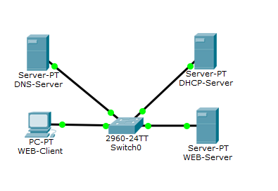
I open CPT and show how it works. This and the following labs will be based on the previous one. Therefore, the addressing will be the same.
Here is added another server that will act as a DNS server and switch. When 3 or more devices appear on the network, a switch is used to connect them.
Let's do the configuration of the DNS server. Go to the "IP Configuration" and write down the IP address with a mask.
Now go to the services and configure the DNS service.
1) In the window "Name" write the name that we want to bind to the IP address. (I wrote the name of my future site, which is being worked on).
2) In the "Address" window, respectively, the IP address, which will work in conjunction with the above written name. (here we indicate the same address as in the laboratory on HTTP - 192.168.1.2).
3) Click the “Add” button to add this entry.
4) Do not forget to include the service itself!
If everything is done correctly, then the picture should be like this.
Now you need to specify the address of the DNS server in the server and computer settings.
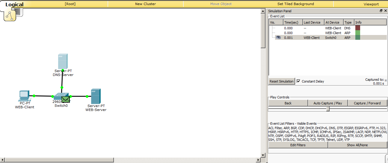
Configuring the DNS server and sites is complete, and it's time to check how this thing works. We switch the environment to the simulation mode and try to access the site from the computer called “cisadmin.ru”.
And we see that 2 envelopes are created. The first is DNS, and the second is ARP. We didn’t really talk about ARP, as this is the topic of the next article. But once he showed himself, then briefly tell you why. As we remember, there is not enough IP address for the exchange between the nodes, as the MAC addresses working on the data link layer are still used. We specified the IP address of the DNS server to the computer. But he does not know what the node with the IP address is 192.168.1.3. The MAC address. It generates an ARP message and throws it into the network. This frame (data on the data link layer is called frames) is broadcast, that is, it will be received by all participants on the same local network (all participants in the same broadcast domain are correct to say, but so far we have not affected this, and I will not load you with this term). And the one with this address will send a return message and report your MAC address. All other participants will drop this frame. Look at the pictures.
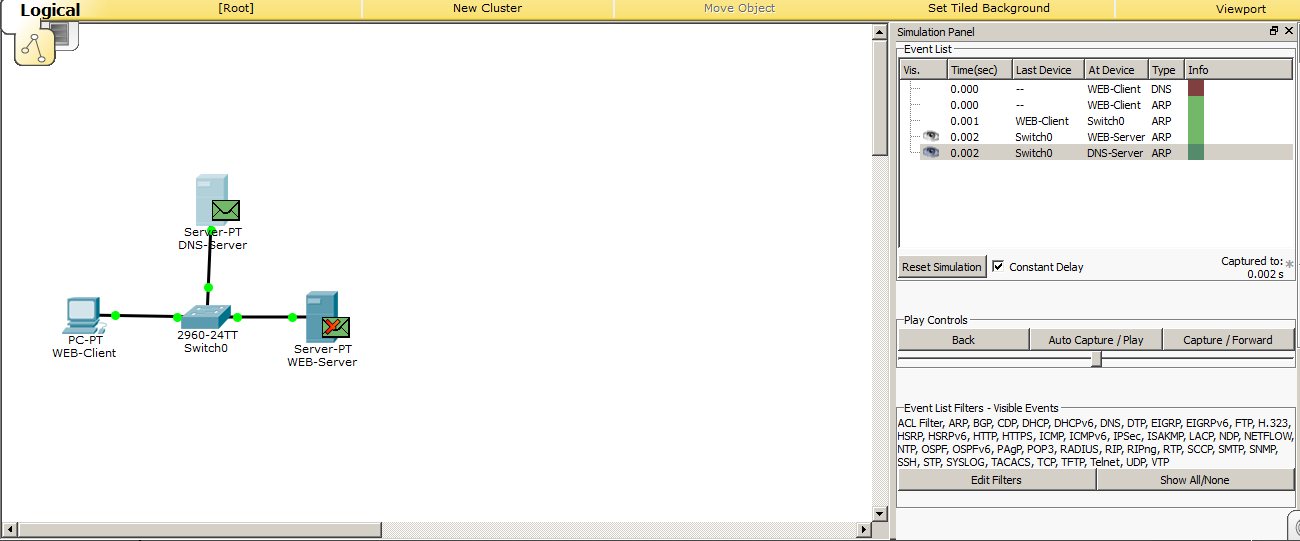
Here is the frame came to the switch, and now his task is to send this frame to all ports, in addition, where he came from.
Frames were sent and see the following. The frame that came to the web server was dropped, as indicated by the crossed-out envelope. Therefore, the frame is discarded. And the DNS server, on the contrary, found out its address and should form a response.
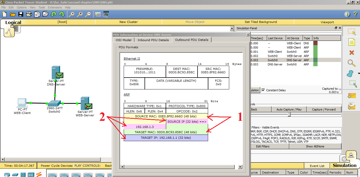
And as you can see, an ARP response was created. Let's break it down a bit.
1) MAC addresses. In the Source MAC, he writes his MAC address, and in the Destination MAC (Target MAC) the address of the computer.
2) In Source IP, your IP address, and in Target IP address of the PC.
I think everything is clear here. If it is not clear, ask. In the next article I will talk about it in more detail.
I click on “Capture / Forward” and see what happens next.
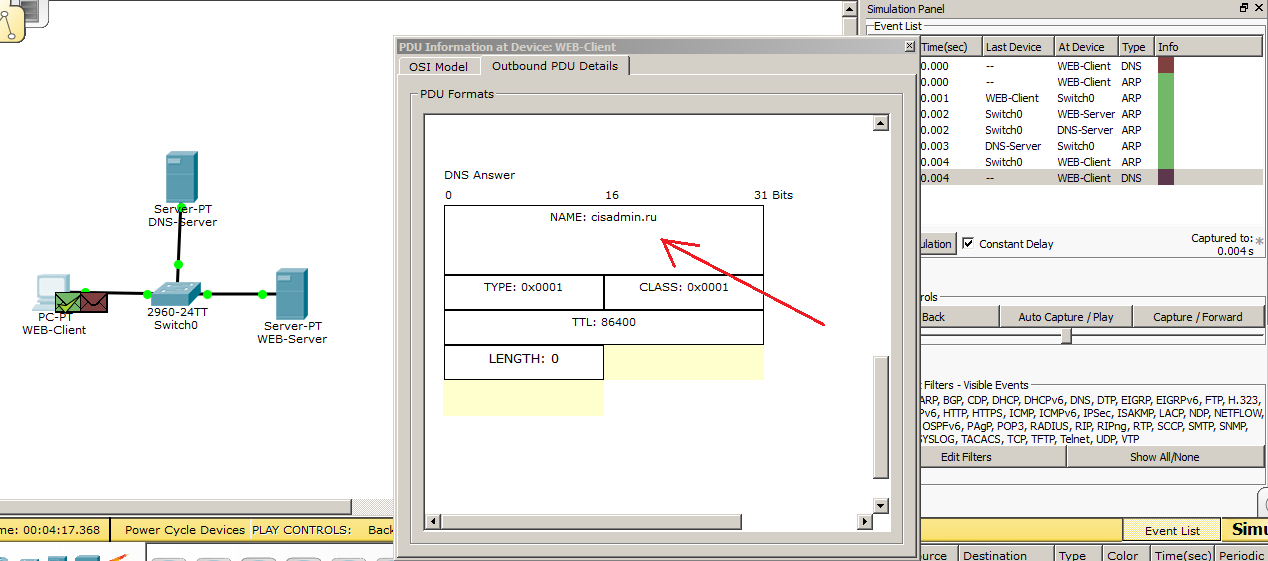
And I see that the computer has successfully received ARP from the server. Now he knows the MAC address of the DNS server, and therefore, how to contact him. And immediately decides to find out from him who this “cisadmin.ru” is. We can open this data and see what he decided to send there. Open "Outbound PDU Details" and go down to the bottom. We see that in the upper “NAME” field he recorded the requested name. Click the button “Capture / Forward” and look.
DNS server receives a DNS request. He climbs into his table and sees that he has such a record, and forms the answer. We open and see that the LENGTH field has changed and is equal to 4. That is, 4 bytes. So much is the IP address. And, accordingly, it records the IP address itself - 192.168.1.2. This is the web server address. Moving on.
We see that the computer received a message from the DNS server, as indicated by a tick on the brown envelope. And now he knows the IP address of the web server. Immediately he tries to establish a TCP session, but a problem arises. He does not know the MAC address of the web server and runs a similar ARP request to find out. We look.
And here is similar to the previous one. The DNS server realized that the message was not for him, and discarded. And the web server finds out its IP address and generates an ARP response.
I got to the computer ARP answer. Now he knows the MAC address of the web server and tries to establish a TCP session. It sends a TCP segment to port 80. Since the TCP protocol has again made itself felt, and in the following protocols it will also appear, then I will briefly explain why it is needed. As you remember from the first article, I said that it establishes the connection. So now every data block that will be sent from the server to the computer will be marked. This is necessary in order for the client to understand whether all the data he received or some lost. And, if any data is lost, he will be able to request it again. Loss of a block of site data can lead to the fact that the site will skew, and it will appear crooked. But now the main thing is to understand that TCP is located at the transport level and works with ports. I specifically opened the window where it is written so that you gradually get used to these fields.
Let's see how the web server will respond to the computer.
The web server sends a response message to the computer and the session is established. And, when everything is ready, the computer generates HTTP and sends it to the web server. Let's see what has changed. And the last line has changed. If earlier there was recorded the IP address of the web server, now there is the domain name “cisadmin.ru”. But do not forget that the domain name here is written only in the application level data. The IP address has not gone away. It is located at the network level. So let's immediately show the IP packet where these addresses are presented.
And as you can see, the IP addresses are in place.
Further, the process is similar to the laboratory for HTTP. Therefore, I will cite the final stage, where, by the name “cisadmin.ru”, a page will open that is located on the server with the IP address 192.168.1.2.
Accordingly, we see that everything works fine, and the site opens by a domain name.
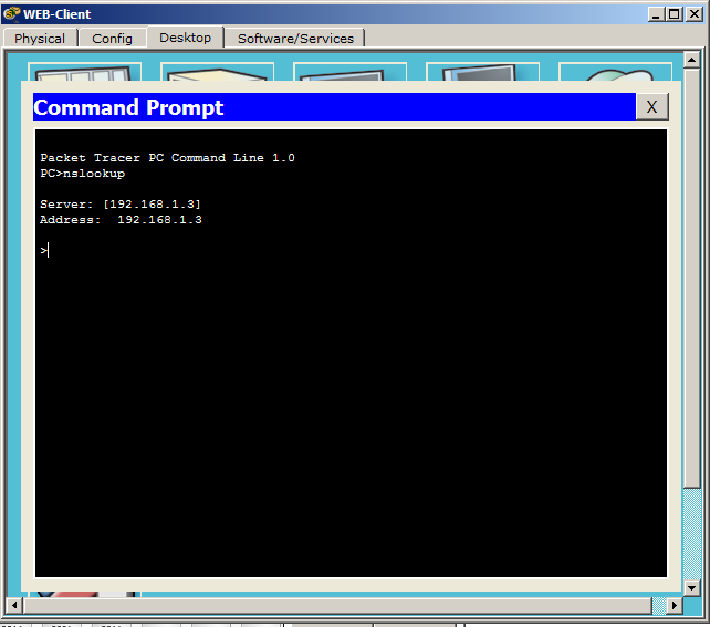
And finally, I will mention one very important utility called nslookup . It allows you to contact the DNS server and find out the name or IP address information from it. In CPT, this command is present, and I suggest looking at it.
We click on the computer on the scheme and on the tab "Desktop" select "Command Prompt". This is an imitation of the command line.
We open a window, like cmd in Windows. You can enter the "?" and press ENTER. It will show a list of all available commands. We need the nslookup command. Enter it and press ENTER.
The utility itself opens, as evidenced by the sign of the bird on the left. Shows us the address of the DNS server and its name. Since there is no name, it duplicates the line with the IP address.
Well, it's time to enter there the domain name and find out what it will give in response.
He gives the name and address, as expected. Basically, when you access a website, he performs this procedure himself. You have seen this query above.
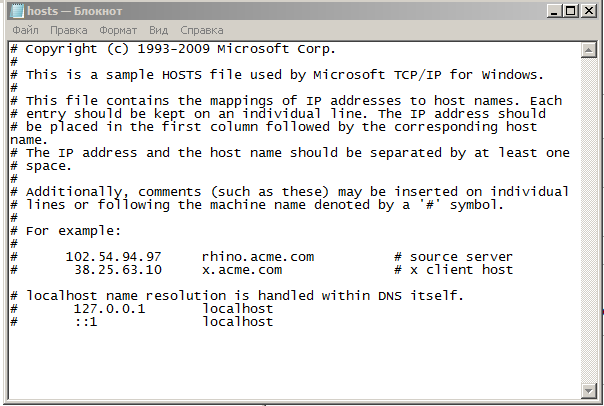
There is another file in each OS that is closely related to DNS. His name is "hosts". Its standard location in Windows systems is "windows \ system32 \ drivers \ etc \ hosts". And in * nix similar systems: "/ etc / hosts". It does the same thing as the DNS server. And this file is controlled by the computer administrator. And the most important: it takes precedence over the DNS server. And, if you have written in the file that the website habrahabr.ru corresponds to the IP address, which actually corresponds to google.ru, then, accordingly, it will open google, not habrahabr. This is often used by attackers when they make corrections to this file. I will give a screen of this file from your computer.
This is how it looks. You can open it at home and realize that it is exactly the same.
Here is such an interesting service and protocol. Also as with HTTP, I will provide a link to download this labs.
And we move on and sort out the DHCP protocol.
Iii) DHCP (Dynamic Host Configuration Protocol). Dynamic Host Configuration Protocol It allows nodes to dynamically obtain IP addresses and other parameters for correct work on the network (main gateway, subnet mask, DNS server addresses). From myself I will say that this protocol saves the life of many sysadmins around the world. Agree that to go and manually register IP parameters for each node is not the most pleasant thing.
With DHCP, you can provide full control over IP addresses: create separate pools for each subnet, issue addresses for rent, reserve addresses and much more.
His work is very difficult for the current understanding. Too many packets, data and frames must be transmitted before the requested address is assigned to the computer.
Let's see how it works in practice.
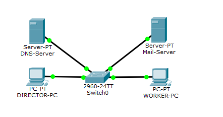
And we see that a new server has been added. Of course, it was possible to give all the roles to one server, but in order for you to understand how the data goes, let there be a separate server for each role.
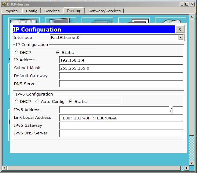
Set up the server.
We assign a free address and mask. Let us turn to the role of DHCP.
1) Select the DHCP service, and a standard pool has already been created here. It can not be deleted. Only change. You can create several pools yourself and do something with them, whatever, even delete. But the standard will always remain. We do not need additional pools, so we will redo the standard one.
2) Here you can add the gateway address, the DNS server address. We have not yet touched the question of the gateway, so for now we will not touch it. We have a DNS server, and you can specify it. Well, let's leave the start addresses as is.
3) Do not forget to turn on the server!
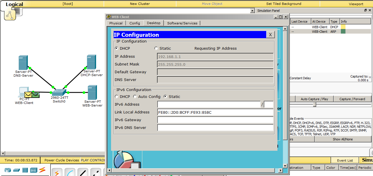
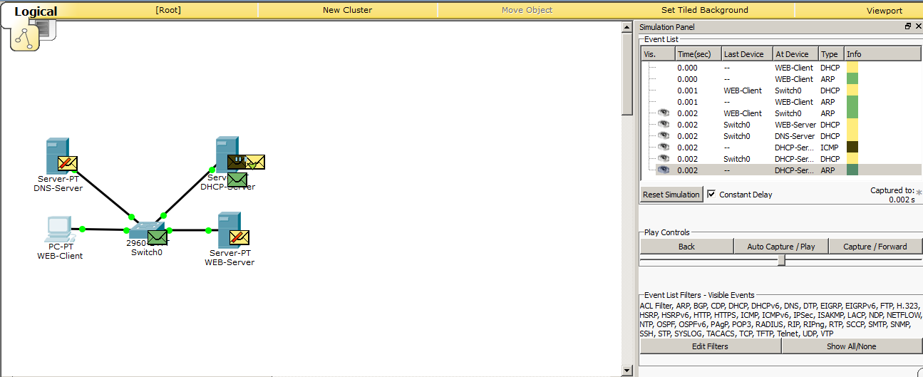
We switch the environment to the simulation mode and see how the computer gets the address.
Accordingly, go to the configuration settings and switch to DHCP.
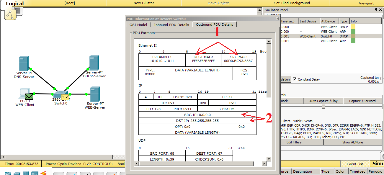
We see that a DHCP request has been created. Let's go through each drop and superficially see what's inside.
1) Data link layer protocol (Ethernet). The address of the computer is recorded in the “Source MAC”. And in the “Destination MAC” is recorded the broadcast address (that is, all).
2) Network layer protocol (IP). The address “0.0.0.0” is recorded in the “Source IP”. This address is inserted when the requested address does not have an address. And in the "Destination IP" is inserted the broadcast address "255.255.255.255".
We look further.
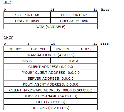
Let's look at the UDP field. Ports 67 and 68 are used here. These are UDP ports reserved for DHCP.
Now we look at the DHCP field. Here, everything is zero, and only in the “CLIENT HARDWARE ADDRESS” field is the MAC address of the computer.
We know how the broadcast works, and see how the network members will react to it.
And we see that all but the DHCP server have dropped the data.
Then I will tell you how the protocol works in words, because a lot of packets and frames will be formed before the DHCP server issues an address. As soon as he receives a request, he begins to look for a free address in the database. As soon as the address is found, the next stage begins - this is the verification of the address. After all, as we remember, the address can be assigned manually, bypassing the DHCP server. This often happens, and even in the corporate environment there are clever people who manually enter the address. For this, the DHCP server sends an ICMP message or ping before issuing this address.
We have not talked about this yet. Therefore, I will say in advance that the ping utility allows you to check the availability of a node by its IP address. And, if someone answers a ping to the DHCP server, then the address is busy and it will repeat the whole procedure, but with a different IP address. But this is also not the most sensible decision. You understand that if a computer with a statically assigned address is turned off, it will not respond to the ping of the DHCP server, and, accordingly, DHCP will decide that the address is not busy and assign it to some node. But, as soon as the computer turns on, 2 computers with the same IP addresses will appear. And then wild miracles can begin. Modern systems have already learned how to respond to this correctly, but still it is not necessary to allow this and it is important to monitor this. I’ll skip all this data in CPT, otherwise I’ll make a filmstrip of monotonous pictures. I will attach this lab belowand you can see for yourself. I will give only the final result, which will form a DHCP-server.
And we see that in the field “YOUR” CLIENT ADDRESS ”the address 192.168.1.1 was added. This is the address that the DHCP server offers to the computer. In the "SERVER ADDRESS" field, the DHCP server adds its address so that the computer knows who offers it the address. In the "CLIENT HARDWARE ADDRESS" field, the MAC address of the computer (that is, the one who requested) is added. And at the very bottom is the option "DHCP Domain Name Server Option". This is the address of the DNS server, which we specified in the DHCP service settings.
Let's see how the computer gets the address.
And we observe the message “DHCP Request Successful”. Which means that the data was successfully received, as evidenced by the completed fields below.
This is how DHCP works. As promised, download link .
Moving on, and the turn came to the protocols POP3 and SMTP. I specifically mentioned these protocols together and now I will explain why.
IV) POP3 (English Post Office Protocol Version 3). Post Office Protocol Version 3. The protocol that clients use to receive mail from the server. Versions 1st and 2nd are outdated and are not used at the present time. It works on the principle of "download and delete." What does it mean?This means that the client enters the server and looks to see if there is a letter for it. And if it is present, it loads it to itself and puts a mark about deletion on the server. Good or bad, a moot point. Someone claims that this is good, since the server is not overloaded with unnecessary letters. I think otherwise. Firstly, the modern infrastructure allows you to store a large amount of letters, and secondly, it often happens that the user deletes or loses an important letter, and then it becomes difficult to find it. Although it is worth mentioning that some clients can be configured so that they do not delete letters from the server. However, with standard settings, they delete emails from the server. Therefore, be careful. The port that he is listening on is 110. A fairly well-known port number, so take notes. Just like the HTTP protocol,He has an enhanced version - POP3S. With the help of an additional cryptographic protocol, like SSL, the contents are encrypted, and the letters are transmitted securely. POP3S uses port 995. We will definitely consider the POP3 protocol in practice, after we learn about the SMTP protocol.
It is worth mentioning about the analogue of POP3. This is the IMAP protocol (Internet Message Access Protocol). Email Access Protocol. It is more intelligent and more complex than POP3. But their main difference is that the client, entering the server, does not delete the mail, but copies it. Thus, the client displays a copy of the mailbox, which is stored on the mail server. And if the client removes any letter from himself, then it is deleted only from him. On the server, the original remains whole. He listens to port 143. It is not possible to consider IMAP in detail in CPT, since it is not fully implemented there.
V) SMTP (English Simple Mail Transfer Protocol).Simple mail transfer protocol. It is used, as you understand, to transfer mail to the mail server. That is why we study POP3 and SMTP in parallel. It uses port 25. This is also important to remember.
It is also important to remember that all mail protocols work over a TCP connection. That is, with the establishment of the connection. Here it is important to get every package safe and sound.
I think from a theoretical point of view, everything is clear. Let's move on to practice and see how it works.
I will open the previous laboratory work on DHCP and slightly upgrade it.
I removed the HTTP server and added a desktop computer instead, and called WORKER-PC. I will assign him the IP address that the HTTP server had. That is, 192.168.1.2. Old computer renamed DIRECTOR-PC. I left the DNS server. We still need it in this lab. DHCP server renamed to Mail-Server. And let's set it up.
I did not change the address, and he remained from the last labs. Let it remain so. Go to the service and find the "EMAIL".
1) In the field "Domain Name" you must write the domain name. This is what will be written after the "@" sign. Mandatory requirement. Any mail is written in this format - login @ domain. And press the "Set" button. I have already pressed it, so it is not active, but if you make changes to the domain name entry field, it will become active again.
2) And create users. In the field "User" we will write the first user. This will be the "Director". And set the password "123". And click on the "+" sign to add it to the database. Similarly, create a second user. This will be “Worker” with the same password “123”.
The creation of users is complete, and we observe the following picture.
1) We see in the database a list of created users. They can be removed, added and changed passwords using the buttons on the right.
2) Do not forget to enable POP3 and SMTP services. They are enabled by default, but verification will not be superfluous.
This completes the server-side configuration, and now we’ll proceed to the client-side configuration. Let's start with the director's computer. Open the "Desktop" tab and select Email.
After that, the settings window will immediately open.
1) In the field “Your Name” we write any name. I will write Director.
2) In the field "Email Address" we write a mailbox. For the director, this is director@cisadmin.ru.
3) In the "Incoming Mail Server" and "Outgoing Mail Server" fields, write the address of the mail server (192.168.1.4)
4) In the field “User Name” we write the login itself. That is, Director and, accordingly, the password 123.
Press the "Save" button, and we open a mail client. CPT called it an email browser.
The same setting will be on the desktop computer. I bring a screen.
Now it's time to see how mail works. Let's first take a look at how it works in real time, and then we will take a closer look at the simulation mode.
Open the mail client on the director's computer and create a letter.
Click on the button “Compose”, and a familiar window opens before us.
Everything is as usual here. We write to whom we send, the subject of the letter, the text of the letter itself and press the button “Send”.
We see the following message that the sending was completed successfully. Wonderful! Now let's see how the letter will be delivered to the worker.
Open the mail client on the desktop computer.
And we see that there is no letter. And all because the client in the CPT does not support automatic updating and you have to do it manually. Push the "Receive" button.
We see the appeared letter and the message on successful receipt. Let's open the letter and see if it’s broken.
And yes, the letter, indeed, came unharmed. We will answer this letter and at the same time check that the letters go both ways. I click the "Reply" button and write the answer.
I send the letter and go to the director's computer. And, accordingly, press the “Receive” button to update the mail.
There was a letter, and below, and a message about the successful receipt.
Open the letter to make sure to the end.
The letter reached, which means everything works.
Let's take a closer look. Switch the environment to simulation mode and send an email. I will not create something new, but just answer the above received letter.
As I said earlier, all mail protocols work with TCP. And this means that before the mail protocol starts to work, and in this case the SMTP protocol, a preliminary connection should be established between the computer and the server. This is what we are seeing now.
Now the process of establishing a connection interests us a little. We are now talking about mail protocols, and therefore I will skip this process and wait for the appearance of SMTP.
1) The long-awaited SMTP appeared, as indicated by the entry in the simulation panel, and open them. Pay attention to TCP ports to make sure that this is it. And we see that in the "Destination Port" is 25 number. And in the “Source Port” a dynamically invented port is recorded so that the server can identify the client. All right
2) We look at the SMTP data below, and there is nothing interesting here. CPT shows us like a normal data block.
Then he sends this data to the server. Let's see what happens next.
The server, receiving data from the computer, generates a response message. Pay attention to the changes. The numbers that were present were swapped, namely the “Source Port” and “Destination Port”. Now the source is the server, and the destination is the computer. This is a message about the delivery of letters to the server.
After that, the SMTP protocol operation is over, and the computer can start to close the TCP session. What he will do.
Now that the letter has been sent, and we know that it is on the server, we will try to receive this letter. Open the desktop computer and click the button "Receive".
As with SMTP, a TCP session is also created in POP3. Let's look at the port numbers. The “Destination Port” is 110 port number. This is the standard port number for POP3. The “Source Port” is port 1028.
We look further and wait for the release of POP3.
Here he appeared and observed that in the POP3 field the same picture as in SMTP, i.e. all that and so it was clear.
Then he sends this request to the server, and the server must respond with a letter if it is there.
We know that it is there and observe how the server generates a response message. And just like with SMTP, it reverses the ports of departure and destination. At the application level, some POP3 data is packed. This is the letter itself.
As soon as the data gets to the computer, they should immediately be displayed in the mail client.
And as soon as the data is received, as indicated here by the check mark on the purple package, the letter is immediately displayed in the client. Further, as in SMTP, will be the closure of the TCP session.
I give a link to download this labs.
And another thing that I would like to show in addition to email protocols is the role of the DNS server. You have seen that when performing any action in the mail client, he wrote to us at the bottom of the server’s IP address. But it is possible to specify not an IP address, but a domain name. Let's see how to do this.
Well, the most logical thing that comes to mind is that we have a mail server with the address 192.168.1.4. And with this address we will have a domain name. Accordingly, we go to the DNS server and match the name to this address.
The configuration on the side of the DNS server is completed, and it remains to change 2 lines in the mail clients of computers. We open the client on the director's computer.
And click on the button "Configure Mail".
The window that we saw during the initial configuration of the client opens.
Here you need to change the lines "Incoming Mail Server" and "Outgoing Mail Server". Instead of the IP address, we write down the domain name and click the “Save” button.
The same is done on the worker’s computer. I will not give extra details, just give a screen.
Immediately try to write a letter to the director and send.
And after clicking the "Send" button, we observe the following.
At the bottom there is a message that he asked the DNS server for the address, and he gave him the IP address of the mail server. Sending was successful.
Now let's go to the director’s computer and click on the “Receive” button.
We receive a letter, and the inscription below indicates successful delivery. Here is another example of using a DNS server on a network.
We have disassembled mail protocols. And proceed to the analysis of the next protocol.
VI) Telnet (from the English. Terminal network). If you translate literally, then this is a network terminal. The foundations of this protocol were laid a long time ago, and so far it has not lost its relevance. It is used to display the text interface, as well as to control the OS. A very useful protocol, and every network engineer must know how to work with it. I will explain why. Each network device, the interface of which is a command line, is configured either using a special console cable or through virtual terminals, which includes the Telnet protocol. And, if the console cable requires a specialist to be located next to the equipment to be configured, then tuning using virtual terminals, and in this case Telnet, does not limit the specialist in distance. You can be in another room, building, city and still have the opportunity to access equipment. I think this is a huge plus. From the minuses of this protocol, I note that it is actually not protected and everything is transmitted in the clear. It uses port 23. And the most popular distributions that work with this protocol are Putty, Kitty, XShell, etc. I think we will consolidate his work in practice.
We will use Telnet to access the Cisco 2960 switch. It, like all Cisco devices, uses the Cisco IOS operating system. And the command line interface is called CLI (Command Line Interface). Let's first set up the switch. We will hang the IP address on it, because without it we will not be able to get to the switch and allow access via Telnet. I will not give screenshots, as there are no graphics. Just give a list of input commands and explain what they are for.
Switch> enable - switch to privileged mode. From here, most teams are available.
Switch # configure terminal - switch to global configuration mode. In this mode, you can enter
commands that allow you to configure general system characteristics. From global configuration mode, you can switch to a variety of configuration modes that are specific to
specific protocol or function.
Switch (config) #username admin secret cisco - create a user with the username admin and the password cisco.
Switch (config) #interface vlan 1 - go to the virtual interface and hang the IP address on it. Here the beauty lies in the fact that it does not matter on which of the 24 ports it will hang. The main thing for us is to have access to it from any port.
Switch (config-if) #ip address 192.168.1.254 255.255.255.0 - assign the last address 192.168.1.254 with the mask 255.255.255.0
Switch (config-if) #no shutdown - the interface is turned off by default, so we turn it on. In IOS, 90% of commands are canceled or disabled by assignment before the “no” command.
Switch (config) #line vty 0 15 - go to the settings of virtual lines where Telnet lives. From 0 to 15 means that we apply this to all lines. You can install up to 16 simultaneous connections on it.
Switch (config-line) #transport input all - and allow the connection for all protocols. I specifically set up for all protocols, since a bit later another protocol will be considered and I do not consider it reasonable to climb here for the sake of one team.
Switch (config-line) #login local - we specify that the account is local, and it will check it with the one we created.
Switch # copy running-config startup-config - be sure to save the configuration. Otherwise, after resetting the switch, everything will reset.
So the switch is configured. Let's connect to it from the work computer. Open the command prompt. We opened it when we looked at nslookup. And we write the following.
That is the telnet command and the address where to connect.
If everything is correct, the next window opens with a request for a login and password.
Accordingly, we write login: admin and password: cisco (we created it on the switch).
And he immediately lets us on the switch. To check, check the availability of the director's computer, using the ping command.
Ping is successful. I hope it is clear that the availability check is performed not from the worker’s computer, but from the switch. The computer here is the control device and that's it. I will not consider it in simulation mode. It works in the same way as mail protocols, that is, a TCP session is created, and after the connection is established, Telnet begins to work. As soon as he fulfills, he begins to break the connection. It's simple. I give a link to download.
Let's now break down the SSH protocol.
VII) SSH (English Secure Shell). Translated from English - a safe shell. Like telnet allows you to manage the OS. Its difference is that it encrypts all traffic and transmitted passwords. Encrypted using the Diffie-Hellman algorithm . Who cares read. Almost all modern OS systems are able to work with this protocol. If you have a choice of which protocol to use, then use SSH. First, you will suffer a little in tuning, and much will not be clear, but it will settle down in time with your head. The main thing to remember now is that the most important difference between SSH and Telnet is that SSH encrypts traffic, but Telnet does not. I think it's time to go to practice and see how it works. We will connect and manage the same switch. Let's try to connect via SSH from the director's computer to the switch.
Here, the command syntax is slightly different than when connected via Telnet. We write ssh with the key l, after we type the login (we have this admin) and the address where we connect (192.168.1.254). Finish this case with the ENTER key. A message is displayed that the connection was closed by an external host. That is, the switch has closed the connection. That's because the keys that work with encryption were not created. I’ll go to the switch and configure it to work properly over SSH.
Switch (config) #hostname SW1 - change the name of the switch. With this standard name, you cannot register a domain that is needed for generating keys.
SW1 (config) #ip domain-name cisadmin.ru - register domain.
SW1 (config) #crypto key generate rsa - generate RSA keys.
The keys for the keys will be: SW1.cisadmin.ru
Choose the size of the modulus in the range of 360 to 2048 for your
General Purpose Keys. Choosing a key modulus greater than 512 may take
a few minutes.
How many bits in the modulus [512]: 1024 - Specify the key size. The default is 512, but I will enter 1024.
% Generating 1024 bit RSA keys, keys will be non-exportable ... [OK]
There is a message about the successful generation of keys.
Setup is complete, and try again to connect to the switch.
And another message is already displayed, asking for a password. Enter the password "cisco" and find ourselves on the switch.
It remains to check the work. I will use the ping command and check the availability of the work computer.
And made sure that everything works fine. I bring the link to make sure you.
And I turn to the next protocol.
VIII) FTP (English File Transfer Protocol). File Transfer Protocol. I think from the name of the protocol it is clear that it transfers files. A very ancient protocol, released in the early 70s. It appeared before HTTP and the TCP / IP stack. As he worked before, he still works according to the “client-server” model. That is, there is the initiator of the connection and the one who listens to it. There are several modifications that support encryption, tunneling, and so on. Previously, different console utilities worked with this protocol, which did not have graphics and they worked by entering certain commands. At the present time there are also graphic programs. The most popular and simple is Filezilla. In CPT, only the console method is implemented.
We proceed to practice. As a basis, I will take the previous lab and replace the mail server with an FTP server.
In principle, the scheme is similar to the previous one.
Open the FTP server and go to the FTP service.
By default, the service is enabled, but it is better to check.
1) I marked 1 in account, which was created by default here. This is a standard account with the login "cisco" and the same password. In the right column we see "Permission" - this is access rights. And we see that this account has all the rights. In the test environment, this is exactly what we need, but when working in a company, always follow the rights of each account.
2) Digit 2 marked FTP repository. Here are mostly firmware for cisc devices.
The service is set up and once everything is so beautiful, we will try to work with it. But first, let's create a text file on the director’s computer, which I then download to the FTP server.
I open the director's computer and select "Text Editor". This is an analog notebook in Windows.
I will write there the text and save it.
Now we will try to upload this file to an FTP server. Open the command line and write
That is, as we remember earlier, the protocol used is written at the beginning, and then the address follows. Next, after the connection, the login is asked (we enter cisco) and the password (also cisco). And after authentication we get to the FTP server itself. The list of available commands can be checked with the "?" Command.
To upload something, use the “put” command, and download the “get” command. Fill our file.
I entered the “put” command and the name of the file I want to copy. And he shows us a message that everything is copied. The file weighs 20 bytes, and the transfer rate is 487 bytes per second. Then I entered the “dir” command to check the contents of the server. And the message.txt file was lit up with the 17th number.
It remains the case for small. This is a download file on the desktop computer. I open WORKER-PC and enter the command line.
I perform almost the same actions as before. Except for the “get” command, not “put”. We see that the file is downloaded. I also entered the "dir" command to show that when downloading a file, the original is not deleted. Download a copy of it.
And once he downloaded the file, it should appear on the computer. I open the “Text Editor” and click File-> Open.
I see that the file is really present and try to open it.
The file came intact. All text is present.
I will not re-clog your head, how it works. Because it works in the same way as mail protocols, Telnet, SSH, and so on. That is, a TCP session is created, and the file transfer / download begins. I will give only the structure of it.
In TCP we pay attention to the port number. This is port 21 (standard FTP port). And in the FTP data field it is indicated that it is some kind of binary data.
This is how the world famous protocol works. More advanced versions are not supported here, but they work in almost the same way. Here is a link to the lab.
And the last protocol that remains is TFTP.
IX) TFTP (English Trivial File Transfer Protocol). Simple file transfer protocol. Invented it in the 80s.Although FTP was quite popular, not all its functions were needed for simple tasks. And a simple analogue was invented. It works via UDP, that is, it does not require connection establishment. Also, it does not require authentication and authorization. It is enough to know its IP address and have it yourself. This is certainly not safe, since the address can be faked. But when a simple protocol is needed and authorization is not required, the choice falls on it. The tsiskov equipment works very closely with it to copy the image or download it to flash-memory.
Nothing teaches better than practice. Therefore, go to her. Miraculously, I discovered that computers in CPT do not know how to work with TFTP. It is good that they did not cut out this function from the tsiskov equipment. Therefore, we will learn from our favorite switch. The scheme remains the same. Just on the FTP server, I will enable the TFTP service.
This is how it looks. The database has a bunch of different firmware for many devices.
Let's go to the switch.
SW1 # dir - command for outputting the contents of the file system
Directory of flash: /
1 -rw- 4414921 c2960-lanbase-mz.122-25.FX.bin
9 -rw- 1168 config.text
64016384 bytes total (59600295 bytes free)
We have There is a file config.text. Let's try to upload it to the TFTP server.
SW1 # copy flash: tftp: - that is, we specify from where, and then where. Here it is from flash-memory on tftp-server
Source filename []? config.text - here it asks for the name of the file to be copied.
Address or name of remote host []? 192.168.1.4 - specify where to copy.
Destination filename [config.text]? - and here you need to specify under what name to save it on the server. By default, it offers to save it with the same name. And if you press the ENTER key, it will select the default name. It suits me, and I will leave it the same.
Writing config.text .... !!!
[OK - 1168 bytes]
1168 bytes copied in 3.048 secs (383 bytes / sec)
And in the final message it shows that everything copied successfully. Let's go to the TFTP server and check.
And I see that he is really there. So the switch did not deceive me.
Now we will try to download something from the server to the switch.
SW1 # copy tftp: flash: - here we write the opposite. First tftp, and then flash
Address or name of remote host []? 192.168.1.4 - TFTP-server address
Next, he will ask what to copy. I do not remember the exact name of the firmware and open TFTP to view.
Write down the name
Source filename []? c2960-lanbasek9-mz.150-2.SE4.bin
Destination filename [c2960-lanbasek9-mz.150-2.SE4.bin]? - here he asks what to call it on the switch itself. I'll press ENTER and leave the default name.
Accessing tftp: //192.168.1.4/c2960-lanbasek9-mz.150-2.SE4.bin ...
Loading c2960-lanbasek9-mz.150-2.SE4.bin from 192.168.1.4: !!!
[OK - 4670455 bytes]
4670455 bytes copied in 0.057 secs (6587503 bytes / sec)
He gave me a message that the download was successful. I check the availability of the firmware with the command "dir".
SW1 # dir
Directory of flash: /
1 -rw- 4414921 c2960-lanbase-mz.122-25.FX.bin
10 -rw- 4670455 c2960-lanbasek9-mz.150-2.SE4.bin
9 -rw- 1168 config.text
64016384 bytes total (54929840 bytes free)
I see that everything is really in place. And in addition, he tells me about the amount of memory and the availability of free space.
We finished to consider top-level protocols. I did not think that it would be such a long article. Perhaps the blame pictures. But I tried as briefly as possible in the case. We considered a lot of protocols, and all of them are irreplaceable. Often help out the life of the sysadmin and our favorite users. Thank you for reading. If something is not clear, leave comments or immediately write in a personal. And I went to put the kettle and drink delicious tea with cakes!
Source: https://habr.com/ru/post/307714/
All Articles