Juniper Hardware Architecture
Modern routers process several million packets per second, work with several FV routing tables, and allow you to implement a huge number of services. Different vendors use a different approach to building equipment. This article will not be a huge number of conclusions. Today we will talk about the architecture of Juniper equipment.
Routers can be divided into two large classes — routers in which the CPU participates in packet forwarding — that is, they have a software-based architecture (for example, Cisco 7200) and routers, in which packet forwarding is performed by hardware (on an ASIC or FPGA) without direct CPU involvement hardware-based (for example, Cisco 65/76). Each of this class of equipment has its pros and cons. Software routers are naturally very cheap, for example, the flagship Miktotik ccr1072-1g-8s costs a little more than 200 thousand rubles and has the performance declared by the vendor higher than that of the Juniper MX80, which costs about 1M rubles. Moreover, in such routers it is easier to implement various functions by adding one or another function to the new version of the software. But as they say in the barrel of honey there is a fly in the ointment - software solutions cannot boast of high performance (for example, you can compare 72 and 76 Tsiski).
The same aforementioned Mikrotik when hanging on its interfaces about 25 filters lose almost 20 times productivity (who is interested, you can see here ), while the same MX80 implements the implementation of filters in hardware, which allows it not to lose in performance. Another bold minus of software solutions is that the CPU processes the control plane and participates in the processing of the data plane at the same time. If, for example, processor utilization due to high utilization of interfaces rises to a critical value (different models have different ways - for some, 80 percent is normal, someone at 35 is already drowning - Nokia switches with a load of 33-35 percent for 2-3 seconds think after entering a command or pressing a tab), the control plane may begin to crumble.
')
Juniper routers are hardware-based solutions. In addition to the above, Juniper routers have a separate control and data plane, which we will discuss later.
Let's talk a little about software: JunOS OS
JunOS OS is FreeBSD, which Juniper engineers have reworked. JunOS, unlike IOS (not IOS XR) has a modular architecture - consists of a kernel and processes that are responsible only for their individual function. Under each process is allocated part of the memory. What does this give us? If a process breaks down in us, suppose the process responsible for vrrp, then it does not pull all the other processes along with it and the same rpd or ppmd processes will work. Naturally for fault-tolerant equipment is a huge plus.
Note: If you look at the same IOS XR, then, unlike the original IOS, it is also built according to a modular scheme.
So, one of the most important elements of JunOS OS is the kernel, as with FreeBSD, it is monolithic . We will not consider the pros and cons of the monolithic core here, if anyone is interested, you can read, for example, on Wikipedia . The kernel performs the basic functions of the OS - process management and interaction between them, for the separation of process access to memory, processor and other RE resources. For the remaining functions - equipment management, routing, monitoring of iron status, etc. there are special processes (daemons) that start when the system boots.
If any of the processes at startup cannot start for any reason, then it will be restarted. If the restart does not lead to a positive result, then information about the problem with this process will be generated in the log so that the engineers can figure out the cause of the problem and fix it.
There are a lot of different processes in JunOS OS, so we will look at the most important ones:
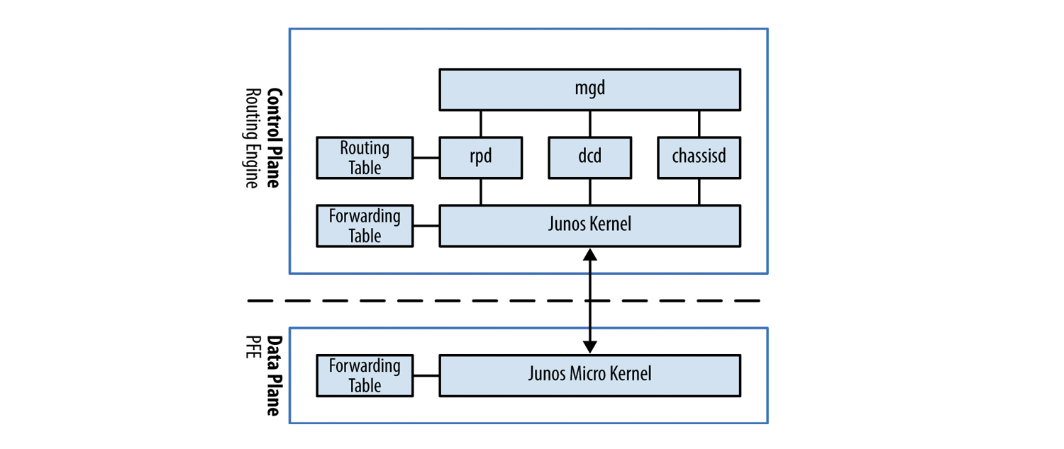
mgd - management daemon. This process is responsible for managing equipment and other processes, the CLI is its client. Thanks to mgd, we can use functions such as rollback, private conguration mode, display part of the configuration in inacive, or apply apply groups.
dd - Device control daemon. This process is responsible for the configuration of the interfaces. It is he who allows us to configure a non-existent interface. This daemon will send the configured interface information to the routing socket so that rpd could later add the route to the routing table.
For example, when we enter the command:
set interfaces xe-0/0/0 unit 0 family inet address 10.0.0.1/30
then the dcd passes to the routing socket the IFD, IFL, IFF, and IFA values, netmask, and forwarding address.
IFD - interface device - physical port on the router (xe-0/0/0);
IFL - interface logical - logical interface number (unit 0);
IFF - interface family - family of addresses (family inet);
IFA - interface address - the address itself (10.0.0.1).

chassisd - chassis daemon. One of the most important processes in JunOS. It is he who is responsible for monitoring the status of all components of the router (from the voltage at various nodes of the router to the speed of rotation of the fans). In case of any problems, this daemon will disable the board and / or the router in order to avoid breakdown or transmit information about the alarmd / craftd problem to the demons, and they, in turn, will generate messages to the log and turn on some of the router's craft panel indicators.
rpd - routing protocol daemon. This process is responsible for all routing protocols, from rip to bgp. He is responsible for maintaining the neighborhood between devices and exchanging route information between them, choosing the best route, creating routing tables and forwarding tables, which are used directly to forward packets.
Note: rpd has a ppmd helper, a process that is responsible for generating and receiving periodic messages — for example, the BFD protocol. We will return to it in the next article, when we talk about the fault tolerance of Juniper equipment.
We will not consider other processes, if interested, a list of all processes with a brief description of JunOS is presented here . Naturally descriptions of processes in English.
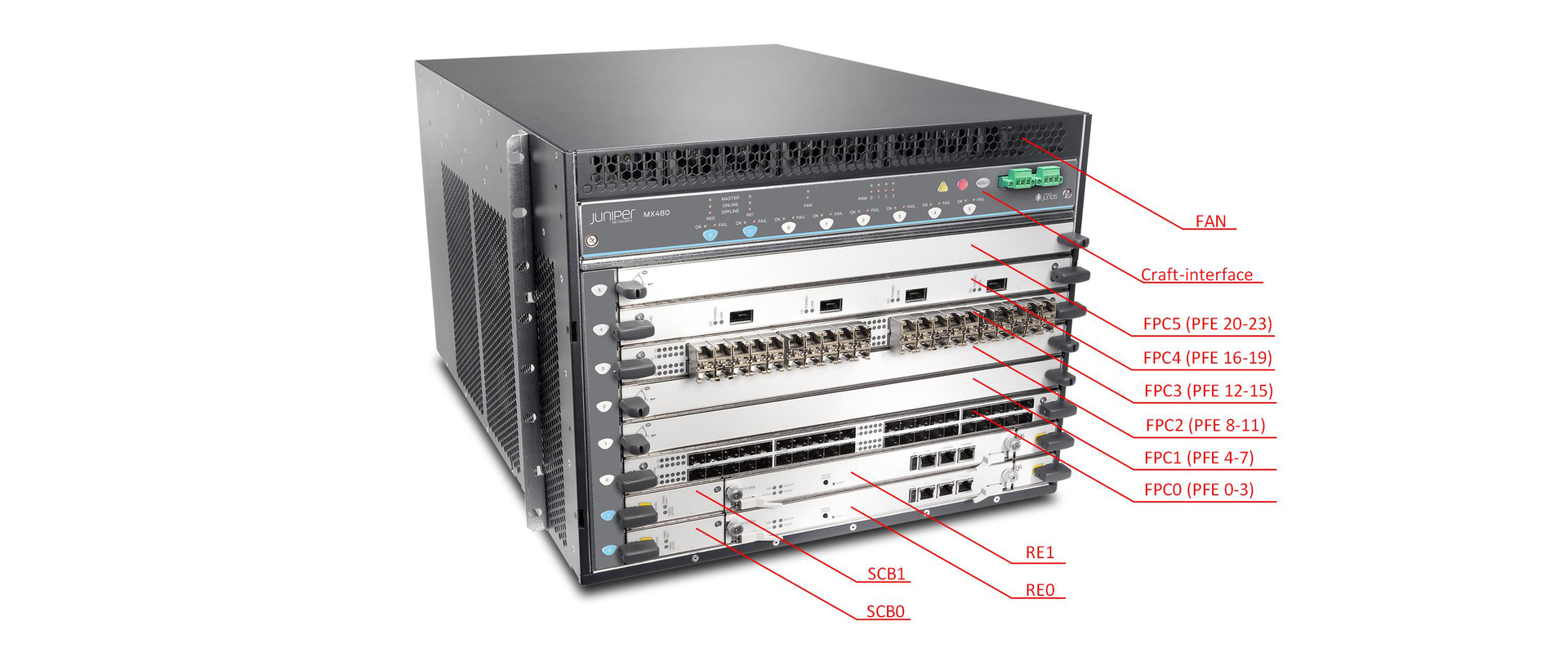
Now let us consider what the Juniper router consists of (we will consider it on the example of the MX series):
And so, Juniper routers consist of several main parts:
- RE (routing engine)
- PFE (packet forwarding engine)
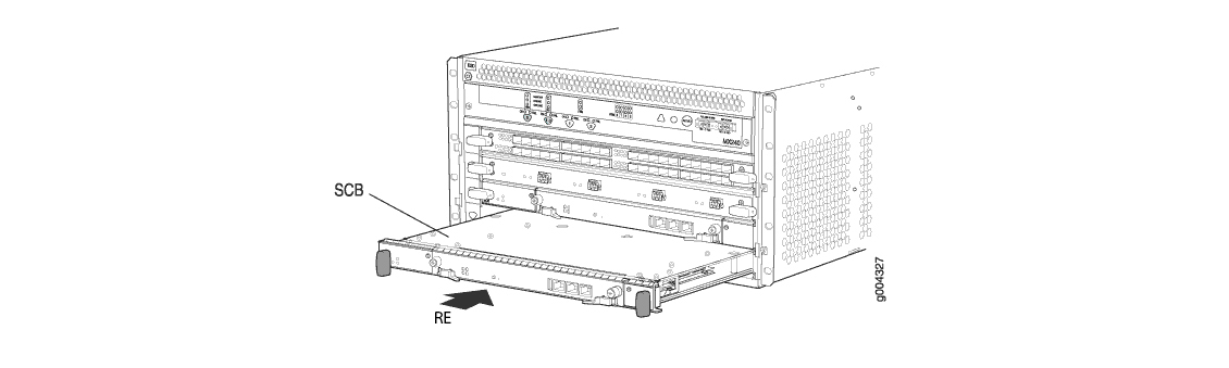
- SCB (Switch and Control Board)
- Midplane
Naturally, the router will not be able to work without a fan unit or, for example, power supply units. But these parts perform a strictly defined function and are not intelligent devices.
Consider the purpose and composition of each element separately.
Routing engine
RE is the brain of the router. He is responsible for the operation of routing protocols (maintaining the neighborhood, exchanging route information, choosing the best route, etc.); for managing the router; for collecting and storing statistics on interfaces, collecting logs and storing necessary files.
RE specifications are available on the Juniper website.
In JunOS, policy is a very powerful tool, but since in the overwhelming majority of cases, policies are associated with routing protocols — which we accept and announce — we run them on RE. RE also processes packets that cannot be processed (or very difficult) in hardware - these are IP packets with options, mpls frames with label 1, ICMP requests to the router, telnet or ssh control.
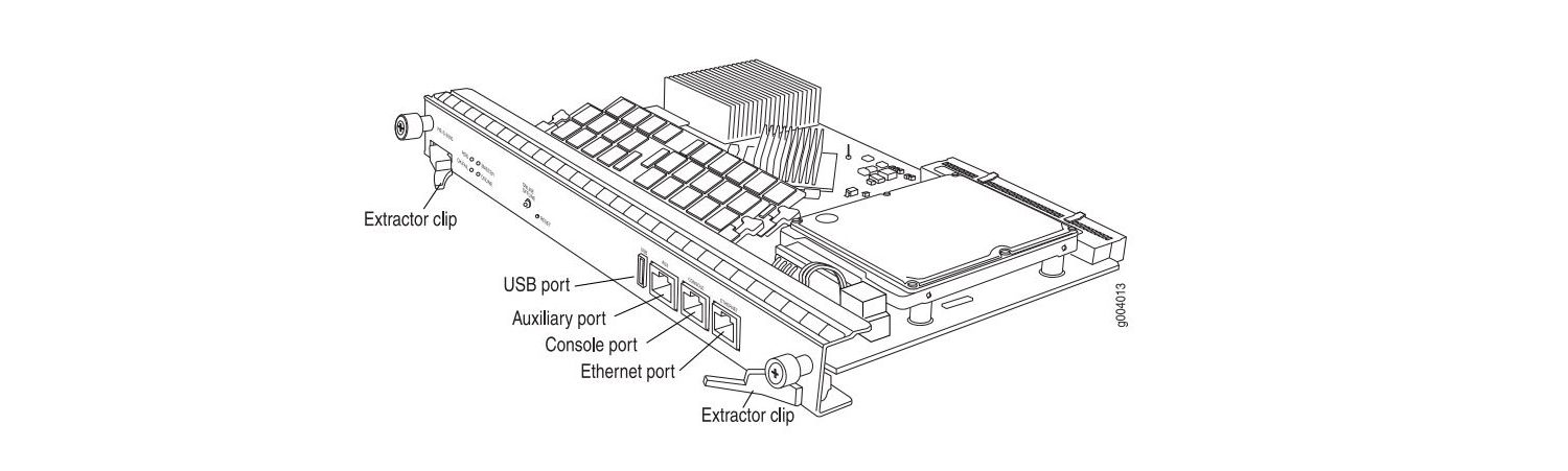
In fact, RE is a full-fledged server that has CPU, RAM, HDD / SSD, Ethernet port, USB port, etc. I think it is not necessary to explain why CPU and RAM are needed, the purpose of the other components should be clarified:
Routing Engine 0 REV 06 740-031116 9009103533 RE-S-1800x4 ad0 3831 MB UGB30SFA4000T1 SFA4000T1 0000079B Compact Flash ad1 30533 MB UGB94ARF32H0S3-KC UNIGEN-478612-001183 Disk 1 usb0 (addr 1) EHCI root hub 0 Intel uhub0 usb0 (addr 2) product 0x0020 32 vendor 0x8087 uhub1 DIMM 0 SGX55N72N2SS2SA-BB DIE REV-52 PCB REV-54 MFR ID-ce80 DIMM 0 SGX55N72N2SS2SA-BB DIE REV-52 PCB REV-54 MFR ID-ce80 DIMM 0 SGX55N72N2SS2SA-BB DIE REV-52 PCB REV-54 MFR ID-ce80 DIMM 0 SGX55N72N2SS2SA-BB DIE REV-52 PCB REV-54 MFR ID-ce80 CF card - a memory card. This card is designed to store the current configuration and used version of JunOS OS.
ad0 3831 MB UGB30SFA4000T1 SFA4000T1 0000079B Compact Flash HDD / SSD - hard or solid state drive. This media is designed to store logs and files.
ad1 30533 MB UGB94ARF32H0S3-KC UNIGEN-478612-001183 Disk 1 USB port. This port is designed to connect external media, for example, to boot and restore the system. The JunOS boot order is as follows: first a USB-flash disk, then a CF-card, and lastly an HDD / SSD. Some REs have two USB ports, for example on the RE MX104.
Ethernet port. The purpose of this port is to manage the router. As a rule, RE is not one, but three ports:
- ethernet
- console
- AUX
Ethernet - port is used to control the equipment (out-of-band management). This port is marked on the system as fxp0.
If you use the show interfaces terse command, then in addition to the fxp0 interface, you can see the em0 and em1 interfaces. These interfaces are designed to communicate with the rest of the router's elements (service cards, line cards).
{master} bormoglotx@test-mx480> show interfaces terse | match em Interface Admin Link Proto Local Remote demux0 up up em0 up up em0.0 up up inet 10.0.0.4/8 em1 up up em1.0 up up inet 10.0.0.4/8 The fxp0 interface is not always used — as you can see on the fxp0 test router, the interface is down because the patchcord is not connected to this port, as indicated by the warning:
{master} bormoglotx@test-mx480> show interfaces terse | match fxp fxp0 up down {master} bormoglotx@test-mx480> show chassis alarms 2 alarms currently active Alarm time Class Description 2011-01-14 12:32:38 MSK Major Host 0 fxp0 : Ethernet Link Down 2011-01-14 12:32:38 MSK Major Host 1 fxp0 : Ethernet Link Down Console - the port is intended for console access.
Auxulary - auxiliary port. In fact, it is similar to the console port, but it has a significant difference: if you connect to the router to the console port during the download, you will see the JunOS OS boot log. Auxulary port at the time of loading the OS is not available, access to the equipment you will receive only after loading the router. In addition, using this port, you can connect to another device in the console port.
On the MX series router (with the exception of the MX5-MX80 junior line), the RE is installed in the switching factory (SCB - it will be discussed below). As a rule, for high fault tolerance, REs are installed by two - one master, the second backup (how it will be described in the next article). If RE is currently a master, then it does not support hot swapping (more precisely, you can pull it out and insert it “live”, but if you do not have GRES / GR or GRES / NSR configured, you will get a traffic loss). But backup RE supports hot swap.
In the process of work, you can switch from master RE to backup. Files stored on a hard disk between REs are not synchronized and when you delete or add a file to the hard disk of one RE, you do not delete or add the file to the second RE. This should be taken into account, for example, when updating the software (it may be that there is no place on one of the REs, when it is full on the second, and so on).
Packet forwarding engine
If RE is the brain of the router, then PFE is kicking and kicking. It is through PFE that all traffic is processed, including the management traffic (if management is not done via the console or the management port on the RE itself). PFE consists of programmable chips that allow you to produce devices:
- search next-hop;
- perform ip / mpls / mac lookup;
- apply QoS;
- apply polysry;
- apply filtering;
- tunneling.
PFE is installed on the interface card. There are boards with 1, 2 or 4 PFE, each PFE serves only its own interface group and interacts with other PFEs via SCB. The interface card has a CPU that controls all the PFEs. The connection between PFE and RE is made via the gigabit switch built into the SCB card.
Note: all interface cards support hot swap.
We consider the composition of the PFE on the example of Trio chipset. Logically, the chipset consists of several blocks:

Memory and Buffering block - this block provides interaction between all other blocks. In conventional boards (without a Q index) it performs the functions of a queue block (naturally, in a more abbreviated version), and in high-capacity boards it performs the function of an interface block.
Lookup block is a multi-core chip that performs ip or mpls lookup, changes the packet headers, applies filters, shapers, QoS. This unit is the heart of PFE. The block works with packet headers and can analyze headers up to 256 bytes in size (which allows implementing various services, such as DDOS protection).
Interface block - this block is present on boards with low bandwidth and performs the function of preliminary classification of incoming packets. If this block is absent, this function is performed by the block of buffering.
Dense Queuing block - a block of extended queues. Presented on the boards with the Q index and allows you to implement H-QoS. In the absence of this block, its functions (naturally in a truncated format) fall on the block of buffering.
Hardware data blocks are represented by the following chips:
Buffering - MQ (Memory and Quering) or XM (enhanced version of this chip)
Lookup block - LU (Lookup Unit) or XL (extended version)
Interface block - IX
Quereing - QX or XQ (extended version)
The blocks are interconnected by HSL2 links, which allows them to quickly exchange data.
There is a large selection of MPC line cards on the market, from MPC1 to MPC9E.
For a complete listing of all line cards, see the Juniper website. Versions differ in the number of installed PFE (MPC1 - 1 PFE, MPC2 - 2 PFE, MPC3E - 1 PFE but extended version). The PFEs installed in these cards themselves differ in the versions of the installed chips (standard or advanced) and the number of installed chips (for example, the MPC4E card uses two PFEs in which 4 LU units are installed). Of course, in addition to improving the installed chips and their number, the amount of SRAM / DRAM also changes, otherwise there will simply be no buffer to pack the packets. The maximum number of PFEs on a single board is 4; in total, there can be 1, 2 or 4 PFEs in one line card.
Switch and Control Board
But the bandwidth of the router as a whole depends not only on PFE, SCB is another important link. Sometimes it is this board that can become a bottleneck. This board is responsible for packet switching between different PFE and connectivity between RE and PFE. Everything else RE is installed in SCB. If this board does not contain a RE master, then it supports hot swapping (traffic loss can be obtained if the cards operate in 3 + 0 redundancy mode).
SCB has three main components: two switching factories and a built-in gigabit switch. Let's talk about each separately.
The built-in gigabit switch is intended for the organization of communication between all elements of a router. Each card in the MX-router has two gigabit internal interfaces (in the output above, two em interfaces were presented on the RE), which connect them to two switches (one for the main one, the other for the backup SCB). It is through this interface that information is transferred between RE and PFE (and between RE). If PFE accepts a packet that needs to be processed in RE, then it is through this gigabit link that the packet is transmitted to the RE, through it, for example, the forwarding table is transferred from the RE to the PFE or the reverse transfer of counter values from the interfaces from the PFE to the RE. SCB has a gigabit external interface through which you can connect to any of the installed cards.

From the output below you can see that we have two line cards installed in slots 0 and 1:
{master} bormoglotx@test-mx480> show chassis fpc Temp CPU Utilization (%) Memory Utilization (%) Slot State (C) Total Interrupt DRAM (MB) Heap Buffer 0 Online 26 10 0 2048 15 16 1 Online 25 14 1 2048 15 24 2 Empty 3 Empty 4 Empty 5 Empty Now, if you look at the state of the links of the built-in switch, you can see that 0 and 1 links are connected to line cards 0 and 1, and 12 and 13 to RE1 and RE0.
{master} bormoglotx@test-mx480> show chassis ethernet-switch Displaying summary for switch 0 Link is good on GE port 0 connected to device: FPC0 Speed is 1000Mb Duplex is full Autonegotiate is Enabled Flow Control TX is Disabled Flow Control RX is Disabled Link is good on GE port 1 connected to device: FPC1 Speed is 1000Mb Duplex is full Autonegotiate is Enabled Flow Control TX is Disabled Flow Control RX is Disabled Link is down on GE port 2 connected to device: FPC2 Link is down on GE port 3 connected to device: FPC3 Link is down on GE port 4 connected to device: FPC4 Link is down on GE port 5 connected to device: FPC5 Link is down on GE port 6 connected to device: FPC6 Link is down on GE port 7 connected to device: FPC7 Link is down on GE port 8 connected to device: FPC8 Link is down on GE port 9 connected to device: FPC9 Link is down on GE port 10 connected to device: FPC10 Link is down on GE port 11 connected to device: FPC11 Link is good on GE port 12 connected to device: Other RE Speed is 1000Mb Duplex is full Autonegotiate is Enabled Flow Control TX is Disabled Flow Control RX is Disabled Link is good on GE port 13 connected to device: RE-GigE Speed is 1000Mb Duplex is full Autonegotiate is Enabled Flow Control TX is Disabled Flow Control RX is Disabled Link is down on GE port 14 connected to device: Debug-GigE Switch fabric
The switching factory is designed to transmit traffic between PFEs. It connects all the PFEs in a full mesh topology. Currently, there are three generations of SCB: SCB, SCBE and SCBE2. Data boards vary in bandwidth. According to the manufacturer's website, SCB supports bandwidths of at least 120 Gbps per slot, SCBE - 160 Gbits and SCBE2 - 340 Gbits per slot. These boards are built on an SF (SCB) and XF (SCBE, SCBE2) chip.
Note: Although SCBE2 provides us with a bandwidth of 340 Gbps / slot, you should not forget about the number of PFEs on the board and the number of interfaces serviced by each PFE. If, for example, take the MPC4E 8x10GE + 2x100GE card, then the total bandwidth of this card is 280 Gbit / s. But since only two expanded PFE (130 Gbit / s bandwidth) are installed on it, the bandwidth of this card is 2x130 Gbit / s = 260 Gbit / s. Here the concept of WAN-groups appears important. Interfaces are grouped together. There are two onboard PICs on this board: on one 8x10GE interface and on the second one on 2x100GE. For PFE, they are combined into WAN groups 0 and 1 (8x10GE - group 0, 2x100GE - group 1). The first PFE serves the first 4GE interfaces from group 0 and the first 100GE interface from group 1. Likewise for PFE1. That is, one PFE serves 140 Gbit / s, but has a capacity of 130 Gbit / s. In total, we get that all ports except two 10GE can operate at the interface speed.
Logically, the PFE to SCB connection is as follows:
For MX960

For MX240 / 480
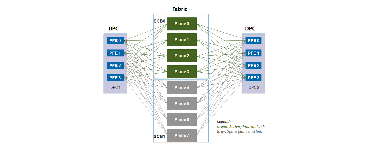
As can be seen from the figures, each SCB is divided into planes. What is a plane? Why, if SCB is inserted into mx480, we will have 4 planes, but if we insert the same board in MX960, then we will have only two planes? To understand this, it is necessary to present the switching factory as a switch with the N-th number of ports. How many ports should there be? The maximum number of PFE per card is 4th. Now let's calculate how many ports you need:

So, it turns out that the maximum possible amount of PFE is 48 . This means that one switching factory should have 48 ports to create a fully connected topology between all PFEs. It turns out that if we install SCB in the MX960, then all 48 interfaces are involved (I can be involved), but if we insert the board in the MX480, then we need only 24 ports out of 48 - 24 ports will be idle. (If you take the MX240 - then the ratio will be even greater). Therefore, the concept of a plein was introduced. One Plain is a virtual switch that provides a fully connected topology between all PFEs. I hope it’s clear now why one switching factory, when installed in the MX960, has only one plane, and the MX480 / 240 already has two. Since there are two switching factories on one SCB, we see that one board provides 2 plains for the MX960 and 4 plains for the MX480 / 240. As a result, taking into account the reservation, we get the following number of planes:

As can be seen from the output below on the MX960, we have 6 patterns:
{master} bormoglotx@test-mx960> show chassis fabric plane-location ------------Fabric Plane Locations------------- Plane 0 Control Board 0 Plane 1 Control Board 0 Plane 2 Control Board 1 Plane 3 Control Board 1 Plane 4 Control Board 2 Plane 5 Control Board 2 But only 4-D Plains are currently active: 2 PLans with SCB3 are designed to increase fault tolerance (2 + 1)
{master} bormoglotx@test-mx960> show chassis fabric summary Plane State Uptime 0 Online 543 days, 13 hours, 34 minutes, 24 seconds 1 Online 543 days, 13 hours, 34 minutes, 23 seconds 2 Online 543 days, 13 hours, 34 minutes, 23 seconds 3 Online 543 days, 13 hours, 34 minutes, 23 seconds 4 Spare 543 days, 13 hours, 34 minutes, 22 seconds 5 Spare 543 days, 13 hours, 34 minutes, 22 seconds 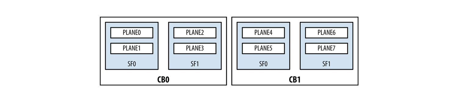
Note: it may be that all 6 plans will be online, which is necessary if the bandwidth of the 2 SCBs is not enough to service all installed cards. Then there will be no reservation (3 + 0).
For the MX480 and MX240, the outputs look slightly different:
{master} bormoglotx@test-mx480> show chassis fabric plane-location ------------Fabric Plane Locations------------- Plane 0 Control Board 0 Plane 1 Control Board 0 Plane 2 Control Board 0 Plane 3 Control Board 0 Plane 4 Control Board 1 Plane 5 Control Board 1 Plane 6 Control Board 1 Plane 7 Control Board 1 We see 8 planes on 2 maps. It uses 1 + 1 redundancy, so only 4 playlins are online.
{master} bormoglotx@test-mx480> show chassis fabric summary Plane State Uptime 0 Online 698 days, 2 hours, 17 minutes, 31 seconds 1 Online 698 days, 2 hours, 17 minutes, 26 seconds 2 Online 698 days, 2 hours, 17 minutes, 26 seconds 3 Online 698 days, 2 hours, 17 minutes, 20 seconds 4 Spare 698 days, 2 hours, 17 minutes, 20 seconds 5 Spare 698 days, 2 hours, 17 minutes, 15 seconds 6 Spare 698 days, 2 hours, 17 minutes, 14 seconds 7 Spare 698 days, 2 hours, 17 minutes, 9 seconds Midplane
The midplane is installed on the back of the chassis and provides electrical connectivity between all the boards and the power supply to each element of the router from the power supplies.
MX80
Separately, I would like to say about the younger line MX5-MX80. This line includes 4 routers - MX5, MX10, MX40 and MX80. In hardware, these are completely identical routers, that is, they all have stuffing like the MX80, the differences are only in color (they are gray in the manner of MX104) and nameplate. By purchasing a license at any time, you can turn the MX5 into the MX80, since the ports and functions are programmatically disabled. Many manufacturers have this practice, for example, Cisco does the same with their ASR or Huawei.
The MX80 itself is different from its older brothers. Due to its architecture, it has a built-in PFE based on a Trio chipset (it has one MQ, one QX and one LU block) and an integrated RE. Since the SCB function would now be reduced to creating a link between RE and PFE, the developer refused it as a separate SCB board. Roughly speaking, the MX80 is a line card and RE, assembled in a dual-unit case. Naturally, this router has no fault tolerance mechanisms, but its cost is much lower than that of its closest brother, the MX240.
I would like to add that Juniper MX series routers do not know how to do out of the box, for example, NAT. For these purposes, there are special service cards Multiservices DPC (MS-DPC), which can be inserted into any of the slots intended for line cards (there are restrictions on the number of cards per box). MS-DPC can provide the following services:
- NAT (in all its forms);
- Session border control (SBC);
- Deep packet inspection (DPI);
- Firewall features.
Service cards support all MX series routers (including the MX80 - there is a slot for a special card on the back of the router). About these cards can be read on the manufacturer's website.
Juniper MX inner-world package travel
based on the book This Week: An Expert Packet Walkthrough on the MX Series 3D
We figured out what the router consists of, but how does a packet transfer from one interface to another? How the package will be processed depends on its type:
- transit packet, incoming and outgoing interface on one PFE;
- transit package, inbound and outbound interface on different PFEs;
- the package which processing will be made on CPU RE;
- package, processing of which will be performed on the interface card CPU;
- package generated by CPU RE;
- package generated by CPU PFE.
We will analyze the most difficult case when a transit packet has an incoming interface in the area of responsibility of one PFE, and the outgoing one - of the other.
So, the packet is accepted on the incoming interface. The packet falls on the MAC controller, which is essentially an interlayer between the physical layer and the channel layer (MAC sublayer). This controller connects the physical interface with the PFE. One of the important functions of the controller is to check the checksum of the received frame (if the sum of the calculated amount does not correspond to that specified in the FCS, then the packet is dropped.
Next, the Trio chipset is included. If we have a low-bandwidth card (for example, twenty gigabit ports), then the PFE will have an interface block (IX chip). This block makes a preliminary classification of packages. This classification is very rough, as it has only three classes for each interface - real time (RT), best effort (BE) and control. The latter class includes management traffic (routing protocols, vrrp, etc.). If we have a more capacious board (for example, 16-a dozen), then this unit will not be on the board. Therefore, the task of the interface unit falls on the block buffering.
A buffering block consists of several blocks (we will consider their functions as the packet advances). After preliminary classification, the packet enters the WAN input block. This block connects all other blocks to itself and is responsible for the segmentation of the received packet, followed by buffering and separating the header to send it to the Lookup block. Now more. Once in this block, the header is separated from the packet, which is placed in a special container - parcel, and the rest of the packet is buffered in OnChip memory (SRAM) fast memory.
Parcel is a container in size from 256 to 320 bytes. Most often, the packet length is 256 bytes. If a packet with a size less than or equal to 320 bytes hit the WI block, this packet is completely placed in the parcel. If the packet is more than 320 bytes in size, then the first 256 bytes are separated from the packet, and the rest of the packet is buffered in OnChip-memory (SRAM).
Parcel, when transmitting from a buffering block to the lookup block, has a special M2L header (MQ to LU), which indicates the class number (to which the packet was assigned during the preliminary classification). Immediately the question arises - why divide the package into two parts and generate parcel? Isn't it easier to use the source package? In this case, too much data will flow inside the chipset (for example, from the buffering unit to the lookup unit and back). There will be difficulties with packet buffering between chipset elements and will increase the load on the connections between them. In our case, the contents of the package are stored in a buffer, while the parcel is processed in the remaining blocks of the chipset.
: WI . 256 , parcel . , .
— : parcel lookup ( 256 ), (SRAM).
. Lookup PPE — packet processor engine RLDRAM, . Lookup c PPE. parcel, lookup parcel PPE ( M2L ), ( ).
IPv4 (, IPv6 ), , , PPE , . ( Lookup , , ). , : (firewall filters), (policers), c DSCP/EXP ( DSCP/EXP), next-hop, RPF check, LAG ECMP . , parcel, ( ttl ipv4 ), parcel . parcel L2M (LU to MQ), , .
. PFE, L2M .
PFE, L2M – FAB. , ID next-hop. Lookup PFE ( PFE next-hop ..).
, Lookup parcel, L2M FAB . LI – lookup input ( ), FAB parcel OffChip memory (DRAM) OnChip OffChip memory, OffChip memory .
PFE -. PFE PFE . PFE, PFE . J-cell (64- ). , PFE OffChip memory , parcel FAB J-cell . PFE, PFE (PFE ID), ( PFE . J-cell Fabric output . , FO . ( , ).
, . – , PFE.
PFE Fabric input , J-cell . FI parcel, FAB J-cell, parcel, FAB M2L lookup , OffChip memory.
Lookup FAB ID next-hop, parcel arp next-hop, L2 , vlan-tag ( ), mpls (). , Lookup QOS, filters, policers . . . , Lookup L2M , , , parcel L2M .
Lookup parcel L2M LI (lookup input) , parcel OffChip memory ( ), . L2M , lookup .
, Wan output (WO) Parcel OffChip memory, . .
, / RE, — CPU , , RE .
, . Thanks for attention!
Source: https://habr.com/ru/post/307696/
All Articles