Porting FreeModbus under STM32. Version from dinar
Good day, amateurs and programming professionals on microcontrollers. This article is devoted to porting the freemodbus library to STM32F100 (the one in discovery vl). Yes, habrahabr already has a similar article , but it seems to me not the most successful. I will use Modbus RTU in slave mode. To successfully port the freemodbus library to a platform without an operating system, you must perform three steps:
1. Register the file port.h
2. set the timer
3. configure usart
So, the plan is made - it's time for work.
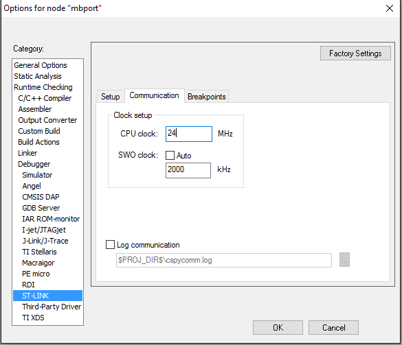
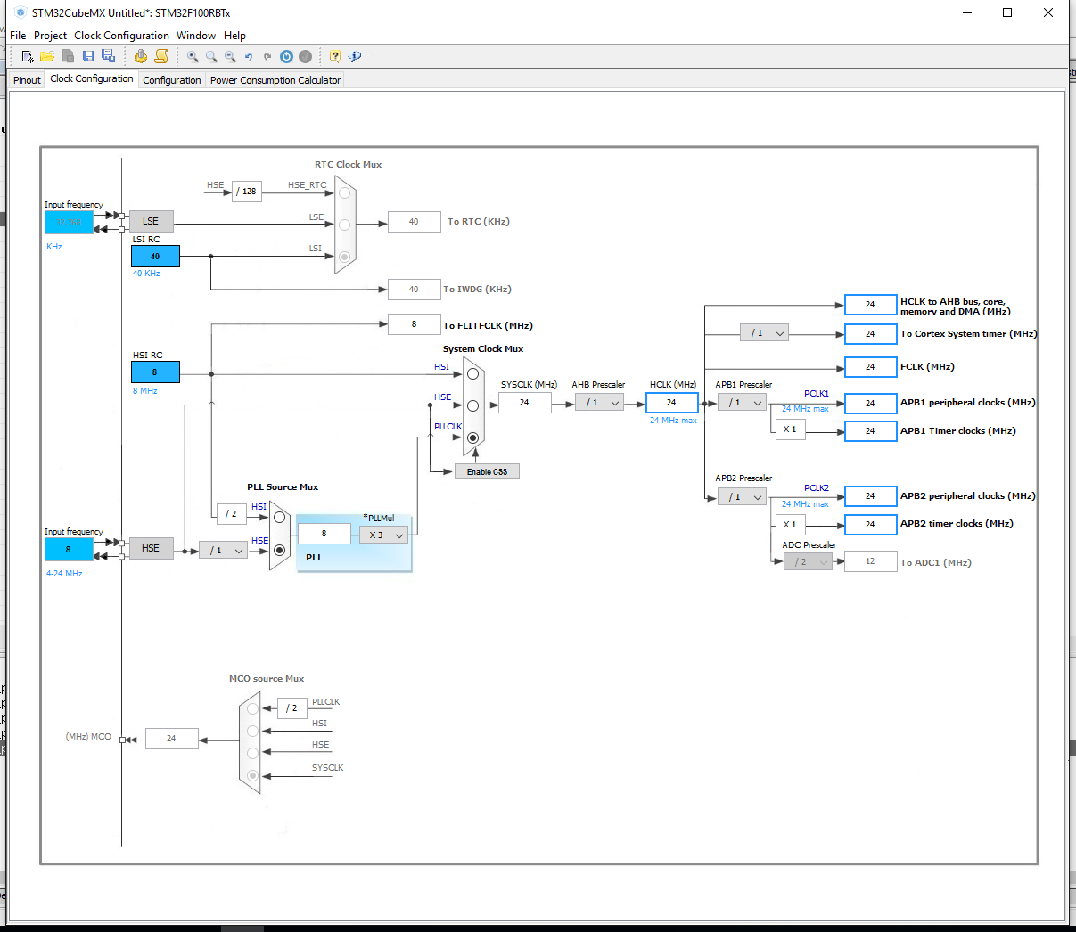
For convenience, we will generate a project using the STM Cube for IAR. We will need to enable debugging, adjust the timer, and I also used the quartz that are present on the board.
')
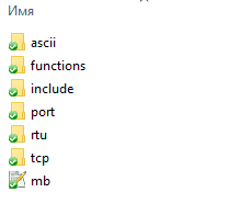
We generate the project. Download freemodbus-v1.5.0 sources. We need a modbus folder. Place it in the project folder in \ Drivers.

There we will place the port folder from freemodbus-v1.5.0 \ demo \ BARE.
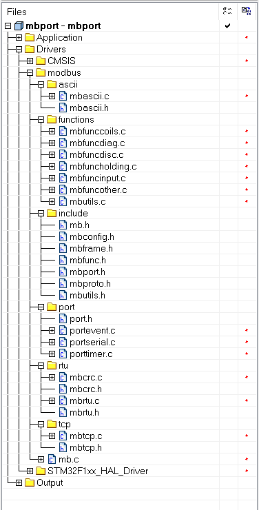
Open the project and attach the newly copied sources to it.
Next, you need to register paths to folders in the project options in the Preprocessor tab.

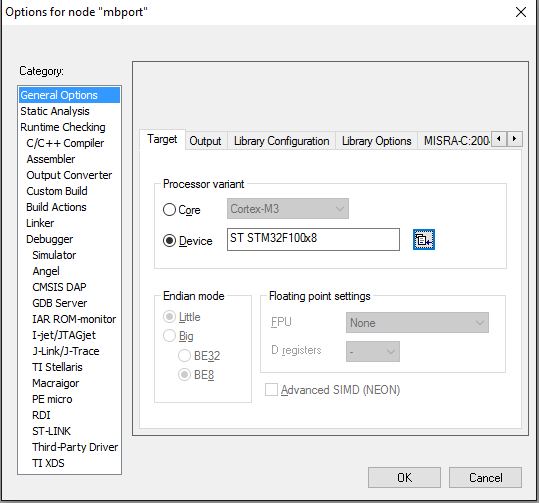
STM QUBE for some reason, it specified as a device none. We fix.
At this stage, the project is going, albeit with warnings. Let's go directly to the porting. Open port.h. Let's declare the functions providing atomicity of operations. Here we will carry out announcements of functions for UART.
I wrote the definition in main ().
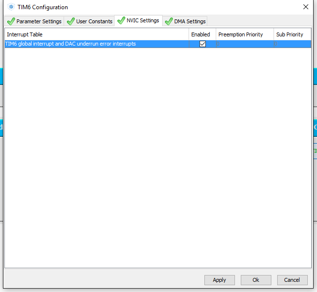
The lion's part of the timer is configured by Qube. It remains only to add a little in porttimer.c. This part is completely written in HAL and does not need extra comments.
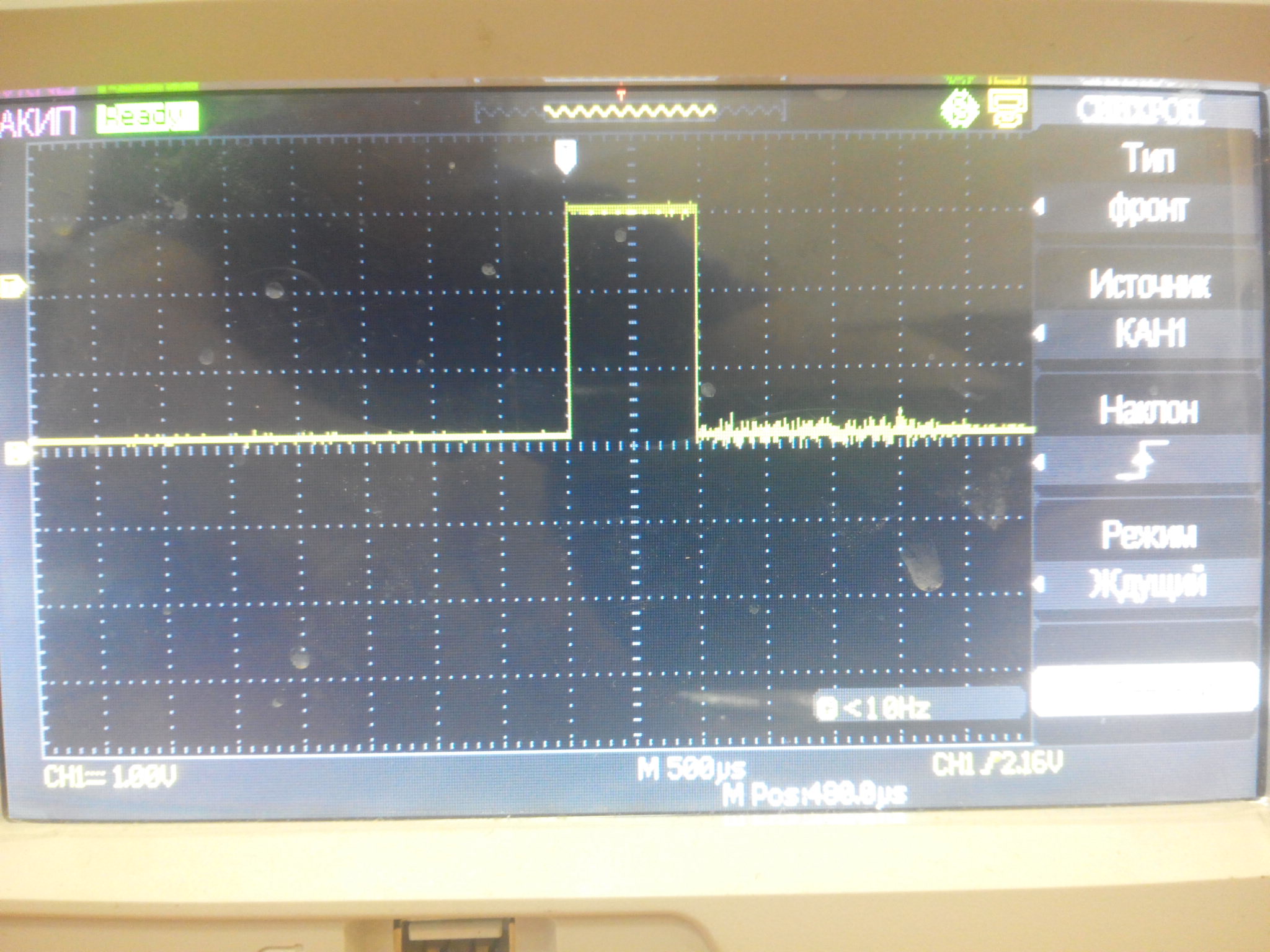
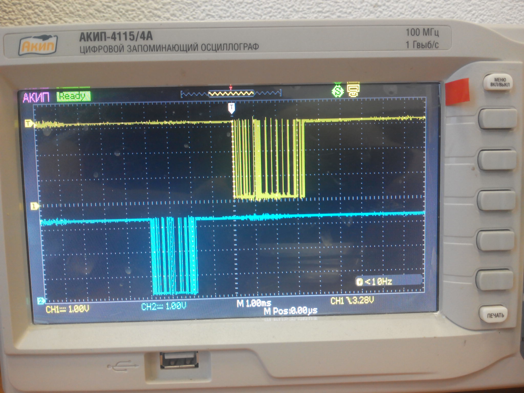
Check that everything goes according to plan. Check that the timings match the expectations. I'll check the old-fashioned method, an oscilloscope. Should get momentum 1ms. Whether vMBPortTimersDisable works - I will not check =)
Temporarily write:

And in main ():

We look:
Now the most interesting thing is setting up UART =) We need to start by writing xMBPortSerialInit and vMBPortSerialEnable. Since GetByte from the library accepts char, I exclude work with 9-bit messages in principle. To write the vMBPortSerialEnable, refer to the USART interrupt scheme.

You can see that to enable an interrupt on reception, you need to enable RXNEIE: RXNE interrupt enable, and the event transmitter is ready - TXEIE: TXE interrupt enable.
The received byte is in the huart_m-> Instance-> DR register. Writing to this register causes a transfer. It's simple. For the convenience of working with USART, add stm32f1xx_hal_uart.c to the project and define HAL_UART_MODULE_ENABLED. I will not write a lot of words, but just show you what's inside.
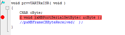
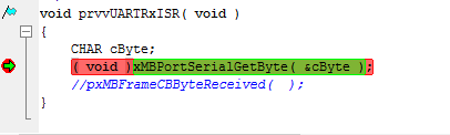
As in the case of the timer - you need to make sure that everything goes according to plan. We are checking. Temporarily prescribe:

We put brekpoint and make sure that when receiving a byte, we get an interrupt. I sent through hercules.
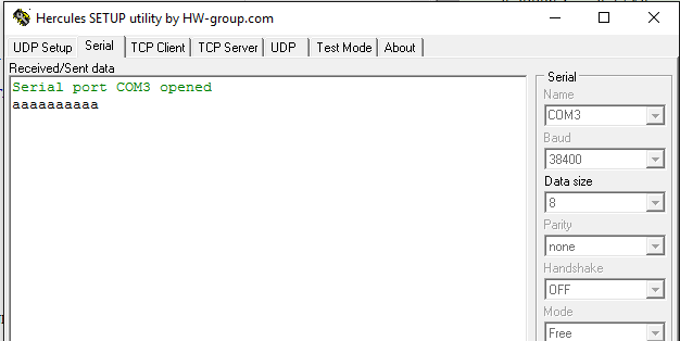
Also check the transmitter. Temporarily prescribe:

We look:
Now let's try to interrogate our device with the help of Modbus Poll.
Works! I hope this article will help beginners, like me, to implement this simple but at the same time useful protocol.
1. Register the file port.h
2. set the timer
3. configure usart
So, the plan is made - it's time for work.
For convenience, we will generate a project using the STM Cube for IAR. We will need to enable debugging, adjust the timer, and I also used the quartz that are present on the board.
STM Cube Screenshots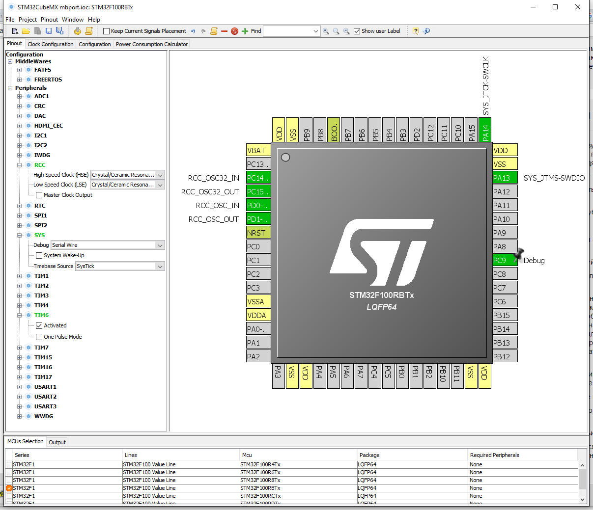

')
We generate the project. Download freemodbus-v1.5.0 sources. We need a modbus folder. Place it in the project folder in \ Drivers.
There we will place the port folder from freemodbus-v1.5.0 \ demo \ BARE.
Open the project and attach the newly copied sources to it.
Next, you need to register paths to folders in the project options in the Preprocessor tab.
STM QUBE for some reason, it specified as a device none. We fix.
At this stage, the project is going, albeit with warnings. Let's go directly to the porting. Open port.h. Let's declare the functions providing atomicity of operations. Here we will carry out announcements of functions for UART.
void __critical_enter(void); void __critical_exit(void); #define ENTER_CRITICAL_SECTION( ) ( __critical_enter( ) ) #define EXIT_CRITICAL_SECTION( ) ( __critical_exit( ) ) void prvvUARTTxReadyISR( void ); void prvvUARTRxISR( void ); I wrote the definition in main ().
static uint32_t lock_nesting_count = 0; void __critical_enter(void) { __disable_irq(); ++lock_nesting_count; } void __critical_exit(void) { /* Unlock interrupts only when we are exiting the outermost nested call. */ --lock_nesting_count; if (lock_nesting_count == 0) { __enable_irq(); } } The lion's part of the timer is configured by Qube. It remains only to add a little in porttimer.c. This part is completely written in HAL and does not need extra comments.
porttimer.c
/* ----------------------- Platform includes --------------------------------*/ #include "port.h" #include "stm32f1xx_hal.h" /* ----------------------- Modbus includes ----------------------------------*/ #include "mb.h" #include "mbport.h" /* ----------------------- static functions ---------------------------------*/ static void prvvTIMERExpiredISR( void ); extern TIM_HandleTypeDef htim6; uint16_t timeout = 0; volatile uint16_t counter = 0; /* ----------------------- Start implementation -----------------------------*/ BOOL xMBPortTimersInit( USHORT usTim1Timerout50us ) { timeout = usTim1Timerout50us; return TRUE; } void vMBPortTimersEnable( ) { /* Enable the timer with the timeout passed to xMBPortTimersInit( ) */ counter=0; HAL_TIM_Base_Start_IT(&htim6); } void vMBPortTimersDisable( ) { /* Disable any pending timers. */ HAL_TIM_Base_Stop_IT(&htim6); } /* Create an ISR which is called whenever the timer has expired. This function * must then call pxMBPortCBTimerExpired( ) to notify the protocol stack that * the timer has expired. */ static void prvvTIMERExpiredISR( void ) { ( void )pxMBPortCBTimerExpired( ); } void HAL_TIM_PeriodElapsedCallback(TIM_HandleTypeDef *htim) { if((++counter)>=timeout) { prvvTIMERExpiredISR(); } } Check that everything goes according to plan. Check that the timings match the expectations. I'll check the old-fashioned method, an oscilloscope. Should get momentum 1ms. Whether vMBPortTimersDisable works - I will not check =)
Temporarily write:
And in main ():
We look:
Now the most interesting thing is setting up UART =) We need to start by writing xMBPortSerialInit and vMBPortSerialEnable. Since GetByte from the library accepts char, I exclude work with 9-bit messages in principle. To write the vMBPortSerialEnable, refer to the USART interrupt scheme.
You can see that to enable an interrupt on reception, you need to enable RXNEIE: RXNE interrupt enable, and the event transmitter is ready - TXEIE: TXE interrupt enable.
The received byte is in the huart_m-> Instance-> DR register. Writing to this register causes a transfer. It's simple. For the convenience of working with USART, add stm32f1xx_hal_uart.c to the project and define HAL_UART_MODULE_ENABLED. I will not write a lot of words, but just show you what's inside.
portserial.c
Now you need to configure interrupts in stm32f1xx_it.c.
#include "port.h" #include "stm32f1xx_hal.h" /* ----------------------- Modbus includes ----------------------------------*/ #include "mb.h" #include "mbport.h" /* ----------------------- static functions ---------------------------------*/ UART_HandleTypeDef huart_m; HAL_StatusTypeDef USART_Init(UART_HandleTypeDef *huart); void USART_MspInit(UART_HandleTypeDef* huart); static void USART_SetConfig(UART_HandleTypeDef *huart); /* ----------------------- Start implementation -----------------------------*/ void vMBPortSerialEnable( BOOL xRxEnable, BOOL xTxEnable ) { /* If xRXEnable enable serial receive interrupts. If xTxENable enable * transmitter empty interrupts. */ if(xRxEnable) { __HAL_UART_ENABLE_IT(&huart_m, UART_IT_RXNE); } else { __HAL_UART_DISABLE_IT(&huart_m, UART_IT_RXNE); } if(xTxEnable) { __HAL_UART_ENABLE_IT(&huart_m, UART_IT_TXE); } else { __HAL_UART_DISABLE_IT(&huart_m, UART_IT_TXE); } } BOOL xMBPortSerialInit( UCHAR ucPORT, ULONG ulBaudRate, UCHAR ucDataBits, eMBParity eParity ) { switch (ucPORT) { case 0: huart_m.Instance = USART1; break; case 1: huart_m.Instance = USART2; break; case 2: huart_m.Instance = USART3; break; default: return FALSE; } huart_m.Init.BaudRate = ulBaudRate; switch (ucDataBits) { case 8: huart_m.Init.WordLength = UART_WORDLENGTH_8B; break; default: return FALSE; } switch (eParity) { case MB_PAR_NONE: huart_m.Init.Parity = UART_PARITY_NONE; break; case MB_PAR_EVEN: huart_m.Init.Parity = UART_PARITY_EVEN; break; case MB_PAR_ODD: huart_m.Init.Parity = UART_PARITY_ODD; break; default: return FALSE; } huart_m.Init.StopBits = UART_STOPBITS_1; huart_m.Init.Mode = UART_MODE_TX_RX; huart_m.Init.HwFlowCtl = UART_HWCONTROL_NONE; huart_m.Init.OverSampling = UART_OVERSAMPLING_16; return (HAL_OK == USART_Init(&huart_m)); } BOOL xMBPortSerialPutByte( CHAR ucByte ) { /* Put a byte in the UARTs transmit buffer. This function is called * by the protocol stack if pxMBFrameCBTransmitterEmpty( ) has been * called. */ huart_m.Instance->DR=ucByte; return TRUE; } BOOL xMBPortSerialGetByte( CHAR * pucByte ) { /* Return the byte in the UARTs receive buffer. This function is called * by the protocol stack after pxMBFrameCBByteReceived( ) has been called. */ if(huart_m.Init.Parity == UART_PARITY_NONE) { *pucByte = (uint8_t)(huart_m.Instance->DR & (uint8_t)0x00FF); } else { *pucByte = (uint8_t)(huart_m.Instance->DR & (uint8_t)0x007F); } return TRUE; } /* Create an interrupt handler for the transmit buffer empty interrupt * (or an equivalent) for your target processor. This function should then * call pxMBFrameCBTransmitterEmpty( ) which tells the protocol stack that * a new character can be sent. The protocol stack will then call * xMBPortSerialPutByte( ) to send the character. */ void prvvUARTTxReadyISR( void ) { pxMBFrameCBTransmitterEmpty( ); } /* Create an interrupt handler for the receive interrupt for your target * processor. This function should then call pxMBFrameCBByteReceived( ). The * protocol stack will then call xMBPortSerialGetByte( ) to retrieve the * character. */ void prvvUARTRxISR( void ) { pxMBFrameCBByteReceived( ); } HAL_StatusTypeDef USART_Init(UART_HandleTypeDef *huart) { /* Check the UART handle allocation */ if(huart == NULL) { return HAL_ERROR; } /* Check the parameters */ if(huart->Init.HwFlowCtl != UART_HWCONTROL_NONE) { /* The hardware flow control is available only for USART1, USART2, USART3 */ assert_param(IS_UART_HWFLOW_INSTANCE(huart->Instance)); assert_param(IS_UART_HARDWARE_FLOW_CONTROL(huart->Init.HwFlowCtl)); } else { assert_param(IS_UART_INSTANCE(huart->Instance)); } assert_param(IS_UART_WORD_LENGTH(huart->Init.WordLength)); assert_param(IS_UART_OVERSAMPLING(huart->Init.OverSampling)); if(huart->State == HAL_UART_STATE_RESET) { /* Allocate lock resource and initialize it */ huart->Lock = HAL_UNLOCKED; /* Init the low level hardware */ USART_MspInit(huart); } huart->State = HAL_UART_STATE_BUSY; /* Disable the peripheral */ __HAL_UART_DISABLE(huart); /* Set the UART Communication parameters */ USART_SetConfig(huart); /* In asynchronous mode, the following bits must be kept cleared: - LINEN and CLKEN bits in the USART_CR2 register, - SCEN, HDSEL and IREN bits in the USART_CR3 register.*/ CLEAR_BIT(huart->Instance->CR2, (USART_CR2_LINEN | USART_CR2_CLKEN)); CLEAR_BIT(huart->Instance->CR3, (USART_CR3_SCEN | USART_CR3_HDSEL | USART_CR3_IREN)); /* Enable the peripheral */ __HAL_UART_ENABLE(huart); /* Initialize the UART state */ huart->ErrorCode = HAL_UART_ERROR_NONE; huart->State= HAL_UART_STATE_READY; return HAL_OK; } void USART_MspInit(UART_HandleTypeDef* huart) { GPIO_InitTypeDef GPIO_InitStruct; if(huart->Instance==USART1) { /* USER CODE BEGIN USART1_MspInit 0 */ /* USER CODE END USART1_MspInit 0 */ /* Peripheral clock enable */ __HAL_RCC_USART1_CLK_ENABLE(); /**USART1 GPIO Configuration PA9 ------> USART1_TX PA10 ------> USART1_RX */ GPIO_InitStruct.Pin = GPIO_PIN_9; GPIO_InitStruct.Mode = GPIO_MODE_AF_PP; GPIO_InitStruct.Speed = GPIO_SPEED_FREQ_HIGH; HAL_GPIO_Init(GPIOA, &GPIO_InitStruct); GPIO_InitStruct.Pin = GPIO_PIN_10; GPIO_InitStruct.Mode = GPIO_MODE_INPUT; GPIO_InitStruct.Pull = GPIO_NOPULL; HAL_GPIO_Init(GPIOA, &GPIO_InitStruct); /* Peripheral interrupt init */ HAL_NVIC_SetPriority(USART1_IRQn, 0, 0); HAL_NVIC_EnableIRQ(USART1_IRQn); /* USER CODE BEGIN USART1_MspInit 1 */ /* USER CODE END USART1_MspInit 1 */ } else if(huart->Instance==USART2) { /* USER CODE BEGIN USART2_MspInit 0 */ /* USER CODE END USART2_MspInit 0 */ /* Peripheral clock enable */ __HAL_RCC_USART2_CLK_ENABLE(); /**USART2 GPIO Configuration PA2 ------> USART2_TX PA3 ------> USART2_RX */ GPIO_InitStruct.Pin = GPIO_PIN_2; GPIO_InitStruct.Mode = GPIO_MODE_AF_PP; GPIO_InitStruct.Speed = GPIO_SPEED_FREQ_HIGH; HAL_GPIO_Init(GPIOA, &GPIO_InitStruct); GPIO_InitStruct.Pin = GPIO_PIN_3; GPIO_InitStruct.Mode = GPIO_MODE_INPUT; GPIO_InitStruct.Pull = GPIO_NOPULL; HAL_GPIO_Init(GPIOA, &GPIO_InitStruct); /* Peripheral interrupt init */ HAL_NVIC_SetPriority(USART2_IRQn, 0, 0); HAL_NVIC_EnableIRQ(USART2_IRQn); /* USER CODE BEGIN USART2_MspInit 1 */ /* USER CODE END USART2_MspInit 1 */ } else if(huart->Instance==USART3) { /* USER CODE BEGIN USART3_MspInit 0 */ /* USER CODE END USART3_MspInit 0 */ /* Peripheral clock enable */ __HAL_RCC_USART3_CLK_ENABLE(); /**USART3 GPIO Configuration PB10 ------> USART3_TX PB11 ------> USART3_RX */ GPIO_InitStruct.Pin = GPIO_PIN_10; GPIO_InitStruct.Mode = GPIO_MODE_AF_PP; GPIO_InitStruct.Speed = GPIO_SPEED_FREQ_HIGH; HAL_GPIO_Init(GPIOB, &GPIO_InitStruct); GPIO_InitStruct.Pin = GPIO_PIN_11; GPIO_InitStruct.Mode = GPIO_MODE_INPUT; GPIO_InitStruct.Pull = GPIO_NOPULL; HAL_GPIO_Init(GPIOB, &GPIO_InitStruct); /* Peripheral interrupt init */ HAL_NVIC_SetPriority(USART3_IRQn, 0, 0); HAL_NVIC_EnableIRQ(USART3_IRQn); /* USER CODE BEGIN USART3_MspInit 1 */ /* USER CODE END USART3_MspInit 1 */ } } static void USART_SetConfig(UART_HandleTypeDef *huart) { uint32_t tmpreg = 0x00; /* Check the parameters */ assert_param(IS_UART_BAUDRATE(huart->Init.BaudRate)); assert_param(IS_UART_STOPBITS(huart->Init.StopBits)); assert_param(IS_UART_PARITY(huart->Init.Parity)); assert_param(IS_UART_MODE(huart->Init.Mode)); /*------- UART-associated USART registers setting : CR2 Configuration ------*/ /* Configure the UART Stop Bits: Set STOP[13:12] bits according * to huart->Init.StopBits value */ MODIFY_REG(huart->Instance->CR2, USART_CR2_STOP, huart->Init.StopBits); /*------- UART-associated USART registers setting : CR1 Configuration ------*/ /* Configure the UART Word Length, Parity and mode: Set the M bits according to huart->Init.WordLength value Set PCE and PS bits according to huart->Init.Parity value Set TE and RE bits according to huart->Init.Mode value */ tmpreg = (uint32_t)huart->Init.WordLength | huart->Init.Parity | huart->Init.Mode ; MODIFY_REG(huart->Instance->CR1, (uint32_t)(USART_CR1_M | USART_CR1_PCE | USART_CR1_PS | USART_CR1_TE | USART_CR1_RE), tmpreg); /*------- UART-associated USART registers setting : CR3 Configuration ------*/ /* Configure the UART HFC: Set CTSE and RTSE bits according to huart->Init.HwFlowCtl value */ MODIFY_REG(huart->Instance->CR3, (USART_CR3_RTSE | USART_CR3_CTSE), huart->Init.HwFlowCtl); /*------- UART-associated USART registers setting : BRR Configuration ------*/ if((huart->Instance == USART1)) { huart->Instance->BRR = UART_BRR_SAMPLING16(HAL_RCC_GetPCLK2Freq(), huart->Init.BaudRate); } else { huart->Instance->BRR = UART_BRR_SAMPLING16(HAL_RCC_GetPCLK1Freq(), huart->Init.BaudRate); } } Now you need to configure interrupts in stm32f1xx_it.c.
void DINAR_UART_IRQHandler(UART_HandleTypeDef *huart) { uint32_t tmp_flag = 0, tmp_it_source = 0; tmp_flag = __HAL_UART_GET_FLAG(huart, UART_FLAG_RXNE); tmp_it_source = __HAL_UART_GET_IT_SOURCE(huart, UART_IT_RXNE); /* UART in mode Receiver ---------------------------------------------------*/ if((tmp_flag != RESET) && (tmp_it_source != RESET)) { prvvUARTRxISR( ); } tmp_flag = __HAL_UART_GET_FLAG(huart, UART_FLAG_TXE); tmp_it_source = __HAL_UART_GET_IT_SOURCE(huart, UART_IT_TXE); /* UART in mode Transmitter ------------------------------------------------*/ if((tmp_flag != RESET) && (tmp_it_source != RESET)) { prvvUARTTxReadyISR( ); } } void USART1_IRQHandler(void) { DINAR_UART_IRQHandler(&huart_m); } void USART2_IRQHandler(void) { DINAR_UART_IRQHandler(&huart_m); } void USART3_IRQHandler(void) { DINAR_UART_IRQHandler(&huart_m); } As in the case of the timer - you need to make sure that everything goes according to plan. We are checking. Temporarily prescribe:
We put brekpoint and make sure that when receiving a byte, we get an interrupt. I sent through hercules.
Also check the transmitter. Temporarily prescribe:
We look:
Now let's try to interrogate our device with the help of Modbus Poll.
Take an example from Demo
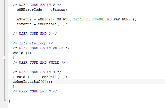
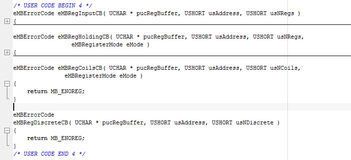
Run a poll
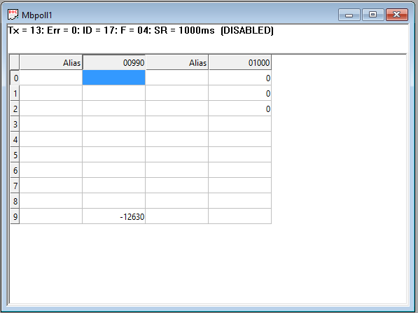
Works! I hope this article will help beginners, like me, to implement this simple but at the same time useful protocol.
Source: https://habr.com/ru/post/307622/
All Articles