Modified Geometry Buffer Anti-Aliasing Algorithm
Aliasing represents one of the fundamental problems of computer graphics, and many different anti-aliasing algorithms have been invented to deal with it. The emergence of MLAA has attracted interest in algorithms that work at the post-processing stage. One of these algorithms (with a small reservation) is Geometry Buffer Anti-Aliasing (GBAA). This material describes an attempt to modify the original algorithm to improve the quality of anti-aliasing in some cases.
GBAA is an enhanced version of the Geometric Post-process Anti-Aliasing Algorithm (GPAA) . The underlying idea is that instead of searching for sharp boundaries in the original image to estimate the location of geometric edges (as MLAA does) you can use the information about the edges in a “pure form” by receiving it from the renderer. The algorithm is pretty simple:
')
The blending of pixel colors (blending) is as follows:
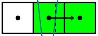
This picture illustrates the logic of the algorithm:
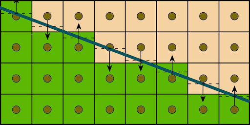
The bold line indicates a geometric edge. The arrows show the selection of the adjacent pixel. Dotted lines indicate offsets relative to the center of the pixel, which are used to calculate blending ratios. Blending is done with a single texture sample: an offset is added to the texture coordinates of the current pixel, and a linear filter does the rest of the work.
In the vertex shader, the coordinates of the geometric edge are projected onto the screen plane and are used to obtain the equation of a straight line on which the edge lies. An equation in the form of a four-dimensional vector falls into a pixel shader, where the coverage and color of a pixel are calculated.
The main advantages of this algorithm are quality and performance. The quality of antialiasing does not depend on the angle of inclination of the edge, which is a traditional problem for post-processing techniques. The first picture shows the results of FXAA with different quality presets, the second shows the results of GPAA.

FXAA 3, FXAA 5

GPAA
The most expensive operation is copying the screen buffer: rendering one frame (in the original implementation) on the HD 5870 video card at 1280x720 resolution is performed in 0.93 ms, of which copying the screen buffer takes 0.08 ms, and the smoothing of the edges is 0.01 ms. The disadvantage is obviously the need to pre-process the geometry to extract edges and additional memory for storing them. In addition, consumer-grade GPUs perform rasterization of lines relatively slowly. Together, these problems adversely affect the scalability of GPAA with the increasing geometric complexity of the scene.
So the GBAA is an advanced version of GPAA. Actually, the improvement is that the directions and distances to the borders of triangles are calculated in a geometric shader, which eliminates the need for preliminary processing of geometry and rasterization of lines, reduces the amount of memory used and, most importantly, eliminates the dependence of performance on the geometric complexity of the scene.
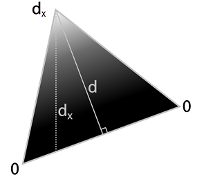
The picture below illustrates the definition of the distance to the borders: for each edge, the geometric shader first calculates the height d , and then the axially aligned distance d x . The results are stored in the vertex attributes, interpolated by the rasterizer and used to calculate blending coefficients in the pixel shader.
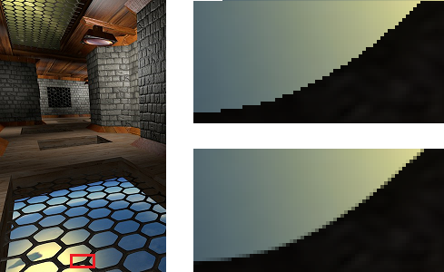
An additional advantage over GPAA is the ability to perform anti-aliasing of not only geometric edges, but also other boundaries, the distance to which can be estimated: for example, boundaries in alpha-transparent textures:
The pixel shader uses the results of the geometry shader calculations to search for edges intersecting a pixel. In case the minimum offset to the edge is less than half a pixel, the next pixel is selected, the blending coefficients are calculated and blending is performed. Otherwise, the pixel remains unchanged. Information about the displacement of silhouette edges is available only for pixels that are on the inside of the silhouette, so these pixels require additional processing:
The GBAA has an unpleasant feature, expressed in artifacts near the converging ribs:
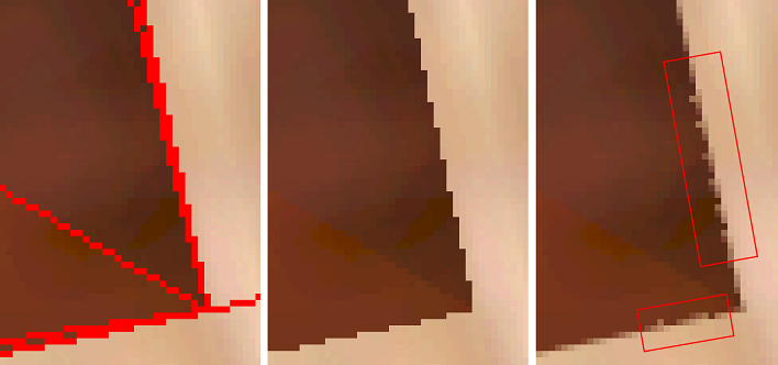
Thin sub-pixel triangles are a source of problems for all post-filtering algorithms that work with the image in screen resolution, and, unfortunately, GBAA is no exception. I tried to understand the mechanism of the occurrence of these artifacts and modify the original algorithm in order to improve the quality of anti-aliasing in problem cases. Consider the first case:
Here, the sampling point of the current pixel in the center falls inside a thin triangle, and the sampling points of the left and right pixels fall into large triangles adjacent to a thin one. If the right edge of a thin triangle is closer to the center of the middle pixel, as shown in the picture, then GBAA will determine the coverage of the right triangle with the middle pixel based on the offset of the right edge relative to its center, and then produce a linearly interpolated color between the middle and right pixels. However, the middle pixel covers fragments of three triangles at once, and if the color of at least one pixel differs from the others, the resulting color will be determined incorrectly. Let a , b , c be the original colors of three pixels, and α , β , γ be the ratio of the areas of the triangle fragments covered with the average pixel to the area of the pixel. The corrected color of the average pixel in this case can be determined by the formula
b out = αa + βb + γc ,
while the original algorithm will calculate it using the formula
b out = (α + β) b + γc
If, for example, the left pixel turns out to be white, and the middle and right pixels turn black, then in the described situation the original algorithm will always produce black for the middle pixel, leaving a fragment of the original image unchanged.
The second case occurs when a thin triangle is located between the centers of two pixels:

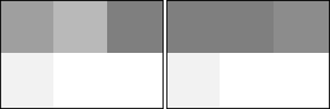
Here, in contrast to the first case, part of the information necessary for calculating the correct color is lost: there is no sample point that would fall inside a thin triangle. To understand how such a case can affect the final image, consider a larger fragment:
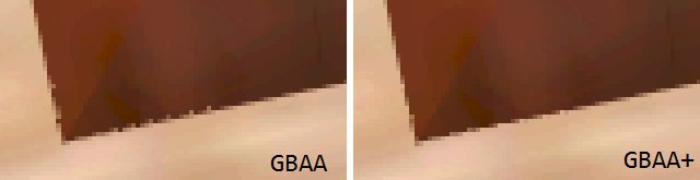
Since, when shifting to the right, the darker triangles are shifted upwards, occupying an ever smaller area, the brightness of the pixels in the upper row should increase. This happens until the queue reaches the last column. The case that arises during its processing was considered earlier. Here the main source of the problem is the first two columns: the upper pixels should get their original color, but instead the original algorithm mixes them with the colors of the lower pixels. On the left is a fragment of the triangle border, obtained using the wrong blending coefficients, on the right - the correct result:
The behavior of the original algorithm in this case can be improved by retaining the original colors of the pixels, between which there is a thin triangle.
To handle these two cases, you can make several changes to the original algorithm.
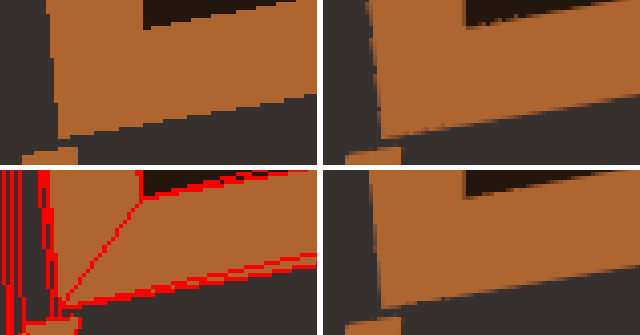
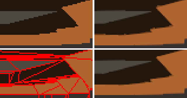
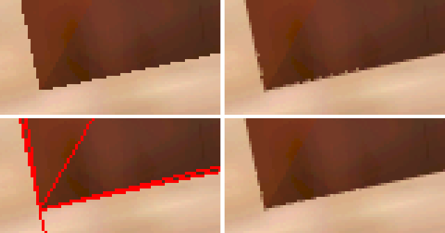
To compare the quality of antialiasing, fragments of the scene were selected, in which the original GBAA produced noticeable artifacts. Then, for each fragment, the camera position was fixed and 4 screenshots were saved: the original image, the original image with highlighted edges, the result of the GBAA and the result of the modified GBAA.

Although the quality of the fragments with converging edges still cannot be called ideal, the artifacts on them became much less noticeable. Scenes with complex textures mask residual effects well. The achieved improvement in quality is obtained at the price of some drop in productivity. If the post-processing stage of the original GBAA took 0.14 ms at a resolution of 1920x1080, then the modified algorithm requires 0.22 ms, which is 57% more. However, even this level of performance continues to be more than satisfactory, leaving behind MLAA and its modifications.
It should be noted that I did not make much effort to optimize the branching in the pixel shader - this could give an increase in performance. New GPU architectures, such as GCN , provide the ability to read vertex attributes in a pixel shader , which allows you to implement an algorithm (both original and modified) without using a geometric shader, eliminating the associated overhead.
Compiled binaries and sources are available on GitHub .
Geometric Post-process Anti-Aliasing (GPAA)
GBAA is an enhanced version of the Geometric Post-process Anti-Aliasing Algorithm (GPAA) . The underlying idea is that instead of searching for sharp boundaries in the original image to estimate the location of geometric edges (as MLAA does) you can use the information about the edges in a “pure form” by receiving it from the renderer. The algorithm is pretty simple:
')
- Render the scene (main pass);
- Make a copy of the backbuffer;
- Render geometric edges in an extra pass, blending the colors of adjacent pixels to get smoothed edges.
The blending of pixel colors (blending) is as follows:
- For each pixel, the direction (vertical or horizontal) and the distance to the nearest edge are determined;
- Using direction and distance, the pixel coverage of the adjacent triangle is calculated;
- The direction is used to select the adjacent pixel, and the coating is used to calculate blending ratios.
This picture illustrates the logic of the algorithm:
The bold line indicates a geometric edge. The arrows show the selection of the adjacent pixel. Dotted lines indicate offsets relative to the center of the pixel, which are used to calculate blending ratios. Blending is done with a single texture sample: an offset is added to the texture coordinates of the current pixel, and a linear filter does the rest of the work.
In the vertex shader, the coordinates of the geometric edge are projected onto the screen plane and are used to obtain the equation of a straight line on which the edge lies. An equation in the form of a four-dimensional vector falls into a pixel shader, where the coverage and color of a pixel are calculated.
Shader Code (HLSL)
struct VsIn { float3 Position0 : Position0; float3 Position1 : Position1; }; struct PsIn { float4 Position : SV_Position; // The parameters are constant across the line so use the nointerpolation attribute. // This is not necessarily required, but using this we can make the vertex shader slightly shorter. nointerpolation float4 KMF : KMF; }; float4x4 ViewProj; float4 ScaleBias; PsIn main(VsIn In) { PsIn Out; float4 pos0 = mul(ViewProj, float4(In.Position0, 1.0)); float4 pos1 = mul(ViewProj, float4(In.Position1, 1.0)); Out.Position = pos0; // Compute screen-space position and direction of line float2 pos = (pos0.xy / pos0.w) * ScaleBias.xy + ScaleBias.zw; float2 dir = (pos1.xy / pos1.w) * ScaleBias.xy + ScaleBias.zw - pos; // Select between mostly horizontal or vertical bool x_gt_y = abs(dir.x) > abs(dir.y); // Pass down the screen-space line equation if (x_gt_y) { float k = dir.y / dir.x; Out.KMF.xy = float2(k, -1); } else { float k = dir.x / dir.y; Out.KMF.xy = float2(-1, k); } Out.KMF.z = -dot(pos.xy, Out.KMF.xy); Out.KMF.w = asfloat(x_gt_y); return Out; } Texture2D BackBuffer; SamplerState Filter; float2 PixelSize; float4 main(PsIn In) : SV_Target { // Compute the difference between geometric line and sample position float diff = dot(In.KMF.xy, In.Position.xy) + In.KMF.z; // Compute the coverage of the neighboring surface float coverage = 0.5f - abs(diff); float2 offset = 0; if (coverage > 0) { // Select direction to sample a neighbor pixel float off = diff >= 0 ? 1 : -1; if (asuint(In.KMF.w)) offset.y = off; else offset.x = off; } // Blend pixel with neighbor pixel using texture filtering and shifting the coordinate appropriately. return BackBuffer.Sample(Filter, (In.Position.xy + coverage * offset.xy) * PixelSize); } The main advantages of this algorithm are quality and performance. The quality of antialiasing does not depend on the angle of inclination of the edge, which is a traditional problem for post-processing techniques. The first picture shows the results of FXAA with different quality presets, the second shows the results of GPAA.
FXAA 3, FXAA 5
GPAA
The most expensive operation is copying the screen buffer: rendering one frame (in the original implementation) on the HD 5870 video card at 1280x720 resolution is performed in 0.93 ms, of which copying the screen buffer takes 0.08 ms, and the smoothing of the edges is 0.01 ms. The disadvantage is obviously the need to pre-process the geometry to extract edges and additional memory for storing them. In addition, consumer-grade GPUs perform rasterization of lines relatively slowly. Together, these problems adversely affect the scalability of GPAA with the increasing geometric complexity of the scene.
Geometry Buffer Anti-Aliasing (GBAA)
So the GBAA is an advanced version of GPAA. Actually, the improvement is that the directions and distances to the borders of triangles are calculated in a geometric shader, which eliminates the need for preliminary processing of geometry and rasterization of lines, reduces the amount of memory used and, most importantly, eliminates the dependence of performance on the geometric complexity of the scene.
The picture below illustrates the definition of the distance to the borders: for each edge, the geometric shader first calculates the height d , and then the axially aligned distance d x . The results are stored in the vertex attributes, interpolated by the rasterizer and used to calculate blending coefficients in the pixel shader.
An additional advantage over GPAA is the ability to perform anti-aliasing of not only geometric edges, but also other boundaries, the distance to which can be estimated: for example, boundaries in alpha-transparent textures:
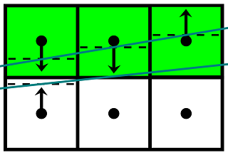
The pixel shader uses the results of the geometry shader calculations to search for edges intersecting a pixel. In case the minimum offset to the edge is less than half a pixel, the next pixel is selected, the blending coefficients are calculated and blending is performed. Otherwise, the pixel remains unchanged. Information about the displacement of silhouette edges is available only for pixels that are on the inside of the silhouette, so these pixels require additional processing:
- Offsets are selected from 4 neighboring pixels;
- Depending on the offset, one of 4 neighbors is selected (the one whose offset corresponds to the direction towards the current pixel):
- left: 0.5 <= offset.x <= 1.0
- right: -1.0 <= offset.x <= -0.5
- upper: 0.5 <= offset.y <= 1.0
- lower: -1.0 <= offset.y <= -0.5 - From the selected offset, a corrected offset is obtained for the current pixel, then all that remains is to calculate the coefficients and perform blending.
Shader Code (HLSL)
struct PsIn { float4 Position : SV_Position; float2 TexCoord : TexCoord; }; [Vertex shader] PsIn main(uint VertexID : SV_VertexID) { // Produce a fullscreen triangle PsIn Out; Out.Position.x = (VertexID == 0)? 3.0f : -1.0f; Out.Position.y = (VertexID == 2)? 3.0f : -1.0f; Out.Position.zw = 1.0f; Out.TexCoord = Out.Position.xy * float2(0.5f, -0.5f) + 0.5f; return Out; } [Fragment shader] Texture2D BackBuffer; Texture2D <float2> GeometryBuffer; SamplerState Linear; SamplerState Point; float2 PixelSize; float4 main(PsIn In) : SV_Target { float2 offset = GeometryBuffer.Sample(Point, In.TexCoord); // Check geometry buffer for an edge cutting through the pixel. [flatten] if (min(abs(offset.x), abs(offset.y)) >= 0.5f) { // If no edge was found we look in neighboring pixels' geometry information. This is necessary because // relevant geometry information may only be available on one side of an edge, such as on silhouette edges, // where a background pixel adjacent to the edge will have the background's geometry information, and not // the foreground's geometric edge that we need to antialias against. Doing this step covers up gaps in the // geometry information. offset = 0.5f; // We only need to check the component on neighbor samples that point towards us float offset_x0 = GeometryBuffer.Sample(Point, In.TexCoord, int2(-1, 0)).x; float offset_x1 = GeometryBuffer.Sample(Point, In.TexCoord, int2( 1, 0)).x; float offset_y0 = GeometryBuffer.Sample(Point, In.TexCoord, int2( 0, -1)).y; float offset_y1 = GeometryBuffer.Sample(Point, In.TexCoord, int2( 0, 1)).y; // Check range of neighbor pixels' distance and use if edge cuts this pixel. if (abs(offset_x0 - 0.75f) < 0.25f) offset = float2(offset_x0 - 1.0f, 0.5f); // Left x-offset [ 0.5 .. 1.0] cuts this pixel if (abs(offset_x1 + 0.75f) < 0.25f) offset = float2(offset_x1 + 1.0f, 0.5f); // Right x-offset [-1.0 .. -0.5] cuts this pixel if (abs(offset_y0 - 0.75f) < 0.25f) offset = float2(0.5f, offset_y0 - 1.0f); // Up y-offset [ 0.5 .. 1.0] cuts this pixel if (abs(offset_y1 + 0.75f) < 0.25f) offset = float2(0.5f, offset_y1 + 1.0f); // Down y-offset [-1.0 .. -0.5] cuts this pixel } // Convert distance to texture coordinate shift float2 off = (offset >= float2(0, 0))? float2(0.5f, 0.5f) : float2(-0.5f, -0.5f); offset = off - offset; // Blend pixel with neighbor pixel using texture filtering and shifting the coordinate appropriately. return BackBuffer.Sample(Linear, In.TexCoord + offset * PixelSize); } Modification
The GBAA has an unpleasant feature, expressed in artifacts near the converging ribs:
Thin sub-pixel triangles are a source of problems for all post-filtering algorithms that work with the image in screen resolution, and, unfortunately, GBAA is no exception. I tried to understand the mechanism of the occurrence of these artifacts and modify the original algorithm in order to improve the quality of anti-aliasing in problem cases. Consider the first case:
Here, the sampling point of the current pixel in the center falls inside a thin triangle, and the sampling points of the left and right pixels fall into large triangles adjacent to a thin one. If the right edge of a thin triangle is closer to the center of the middle pixel, as shown in the picture, then GBAA will determine the coverage of the right triangle with the middle pixel based on the offset of the right edge relative to its center, and then produce a linearly interpolated color between the middle and right pixels. However, the middle pixel covers fragments of three triangles at once, and if the color of at least one pixel differs from the others, the resulting color will be determined incorrectly. Let a , b , c be the original colors of three pixels, and α , β , γ be the ratio of the areas of the triangle fragments covered with the average pixel to the area of the pixel. The corrected color of the average pixel in this case can be determined by the formula
b out = αa + βb + γc ,
while the original algorithm will calculate it using the formula
b out = (α + β) b + γc
If, for example, the left pixel turns out to be white, and the middle and right pixels turn black, then in the described situation the original algorithm will always produce black for the middle pixel, leaving a fragment of the original image unchanged.
The second case occurs when a thin triangle is located between the centers of two pixels:
Here, in contrast to the first case, part of the information necessary for calculating the correct color is lost: there is no sample point that would fall inside a thin triangle. To understand how such a case can affect the final image, consider a larger fragment:
Since, when shifting to the right, the darker triangles are shifted upwards, occupying an ever smaller area, the brightness of the pixels in the upper row should increase. This happens until the queue reaches the last column. The case that arises during its processing was considered earlier. Here the main source of the problem is the first two columns: the upper pixels should get their original color, but instead the original algorithm mixes them with the colors of the lower pixels. On the left is a fragment of the triangle border, obtained using the wrong blending coefficients, on the right - the correct result:
The behavior of the original algorithm in this case can be improved by retaining the original colors of the pixels, between which there is a thin triangle.
To handle these two cases, you can make several changes to the original algorithm.
- The correct calculation of the pixel color in the case of the first case requires the presence of information about the second offset, while the original algorithm stores only one. This will require additional space in the geometric buffer. If there is a second offset along the same axis as the first, but opposite to it, then this offset must also be stored in a geometric buffer. At the post-processing stage, in order to determine the triple coverage case, it is necessary to check whether the pixel intersects with two edges from different sides, and if it intersects, calculate the corrected color.
- The processing of the second case has a minimal effect on the structure of the algorithm, requiring additional checks to be made during the post-processing stage. A pixel should receive its original color if there is a neighboring pixel in the direction of the corresponding offset, which corresponds to the opposite offset direction in the same axis.
Shader Code (HLSL)
struct PsIn { float4 Position : SV_Position; float2 TexCoord : TexCoord; }; [Vertex shader] PsIn main(uint VertexID : SV_VertexID) { // Produce a fullscreen triangle PsIn Out; Out.Position.x = (VertexID == 0)? 3.0f : -1.0f; Out.Position.y = (VertexID == 2)? 3.0f : -1.0f; Out.Position.zw = 1.0f; Out.TexCoord = Out.Position.xy * float2(0.5f, -0.5f) + 0.5f; return Out; } [Fragment shader] Texture2D BackBuffer; Texture2D <float2> GeometryBuffer; Texture2D <float> InvGeometryBuffer; SamplerState Linear; SamplerState Point; float2 PixelSize; int Tweak; int ShowEdges; void check_opposite_neighbor(float2 tex_coord, inout float2 offset) { // Select major offset float2 off; bool x_major = abs(offset.x) < abs(offset.y); if (x_major) off = float2(sign(offset.x), 0); else off = float2(0, sign(offset.y)); // Select neighbor's offset float2 opp_offset = GeometryBuffer.Sample(Point, tex_coord + off*PixelSize); // Make sure it is valid bool apply_offset = true; if (min(abs(opp_offset.x), abs(opp_offset.y)) < 0.5f) { // Make sure it points towards current sample // if so - don't apply texture coordinate offset if (x_major) { if (sign(offset.x)!=sign(opp_offset.x) && abs(opp_offset.x) < 0.5f) offset = 0.5f; } else { if (sign(offset.y)!=sign(opp_offset.y) && abs(opp_offset.y) < 0.5f) offset = 0.5f; } } } float4 main(PsIn In) : SV_Target { float2 offset = GeometryBuffer.Sample(Point, In.TexCoord); bool edge_found = false; bool triple_coverage = false; float4 result; // Check geometry buffer for an edge cutting through the pixel. [flatten] if (min(abs(offset.x), abs(offset.y)) >= 0.5f) { // If no edge was found we look in neighboring pixels' geometry information. This is necessary because // relevant geometry information may only be available on one side of an edge, such as on silhouette edges, // where a background pixel adjacent to the edge will have the background's geometry information, and not // the foreground's geometric edge that we need to antialias against. Doing this step covers up gaps in the // geometry information. offset = 0.5f; // We only need to check the component on neighbor samples that point towards us float offset_x0 = GeometryBuffer.Sample(Point, In.TexCoord, int2(-1, 0)).x; float offset_x1 = GeometryBuffer.Sample(Point, In.TexCoord, int2( 1, 0)).x; float offset_y0 = GeometryBuffer.Sample(Point, In.TexCoord, int2( 0, -1)).y; float offset_y1 = GeometryBuffer.Sample(Point, In.TexCoord, int2( 0, 1)).y; // Check range of neighbor pixels' distance and use if edge cuts this pixel. if (abs(offset_x0 - 0.75f) < 0.25f) { edge_found = true; offset = float2(offset_x0 - 1.0f, 0.5f); // Left x-offset [ 0.5 .. 1.0] cuts this pixel } if (abs(offset_x1 + 0.75f) < 0.25f) { edge_found = true; offset = float2(offset_x1 + 1.0f, 0.5f); // Right x-offset [-1.0 .. -0.5] cuts this pixel } if (abs(offset_y0 - 0.75f) < 0.25f) { edge_found = true; offset = float2(0.5f, offset_y0 - 1.0f); // Up y-offset [ 0.5 .. 1.0] cuts this pixel } if (abs(offset_y1 + 0.75f) < 0.25f) { edge_found = true; offset = float2(0.5f, offset_y1 + 1.0f); // Down y-offset [-1.0 .. -0.5] cuts this pixel } } else { edge_found = true; if (Tweak) { float inv_offset = InvGeometryBuffer.Sample(Point, In.TexCoord); if (inv_offset != 0.0f) { triple_coverage = true; // Sample two neighbors float maj_offset; float2 off = 0; if (abs(offset.x) < abs(offset.y)) { off.x = -sign(inv_offset); maj_offset = offset.x; } else { off.y = -sign(inv_offset); maj_offset = offset.y; } float4 n1 = BackBuffer.Sample(Point, In.TexCoord + off*PixelSize); float4 n2 = BackBuffer.Sample(Point, In.TexCoord - off*PixelSize); // Calculate coverage for this sample (b) and two neighbors (a, c) float alpha = 0.5f-abs(maj_offset); // a (n1) float gamma = 0.5f-abs(inv_offset); // c (n2) float beta = 1-alpha-gamma; // b (this) // Blend final color result = alpha*n1 + beta*BackBuffer.Sample(Point, In.TexCoord) + gamma*n2; } else check_opposite_neighbor(In.TexCoord, offset); } } if (ShowEdges && edge_found) result = float4(1, 0, 0, 1); else if (!triple_coverage) { // Convert distance to texture coordinate shift float2 off = (offset >= float2(0, 0))? float2(0.5f, 0.5f) : float2(-0.5f, -0.5f); offset = off - offset; // Blend pixel with neighbor pixel using texture filtering and shifting the coordinate appropriately. result = BackBuffer.Sample(Linear, In.TexCoord + offset * PixelSize); } return result; } Tests
To compare the quality of antialiasing, fragments of the scene were selected, in which the original GBAA produced noticeable artifacts. Then, for each fragment, the camera position was fixed and 4 screenshots were saved: the original image, the original image with highlighted edges, the result of the GBAA and the result of the modified GBAA.
Although the quality of the fragments with converging edges still cannot be called ideal, the artifacts on them became much less noticeable. Scenes with complex textures mask residual effects well. The achieved improvement in quality is obtained at the price of some drop in productivity. If the post-processing stage of the original GBAA took 0.14 ms at a resolution of 1920x1080, then the modified algorithm requires 0.22 ms, which is 57% more. However, even this level of performance continues to be more than satisfactory, leaving behind MLAA and its modifications.
Conclusion
It should be noted that I did not make much effort to optimize the branching in the pixel shader - this could give an increase in performance. New GPU architectures, such as GCN , provide the ability to read vertex attributes in a pixel shader , which allows you to implement an algorithm (both original and modified) without using a geometric shader, eliminating the associated overhead.
Compiled binaries and sources are available on GitHub .
Source: https://habr.com/ru/post/307366/
All Articles