Basics of computer networks. Subject number 1. Basic network terms and network models
Hello. The other day the idea arose to write articles about the basics of computer networks, to analyze the work of the most important protocols and how networks are built in simple language. Interested I invite under kat.
A little offtopic: About a month ago, I passed the CCNA exam (at 980/1000 points) and a lot of material remained for the year of my preparation and training. I first studied at the Cisco Academy for about 7 months, and the remaining time kept notes on all the topics that I had studied. He also advised many guys in the field of network technologies and noticed that many are attacking the same rake, in the form of gaps on some key topics. The other day, a couple of guys asked me to explain what networks are and how to work with them. In this regard, I decided to describe the most key and important things in the most detailed and simple language. Articles will be useful for beginners who have just embarked on the path of learning. But, perhaps, experienced system administrators will emphasize something useful from this. Since I will follow the CCNA program, it will be very useful to those people who are preparing for the surrender. You can keep the articles in the form of cheat sheets and periodically review them. During my studies I took notes on books and periodically read them to refresh my knowledge.
In general, I want to give advice to all beginners. My first serious book was Oliferov's Computer Networks. And it was very hard for me to read it. Not to say that everything was hard. But the moments where it was understood in detail how MPLS or carrier-grade Ethernet works, introduced into a stupor. I read one chapter for several hours and still much remained a mystery. If you understand that some terms do not want to go into your head, skip them and read further, but in no case do not discard the book completely. This is not a novel or epic, where it is important to read chapters to understand the plot. Time will pass and what was previously incomprehensible, in the end it will become clear. Here is pumped "book skill." Each next book is read easier than the previous book. For example, after reading “Computer Networks” by Oliferov, it is easier to read Tanenbaum “Computer Networks” several times and vice versa. Because there are fewer new concepts. Therefore, my advice: do not be afraid to read books. Your efforts in the future will bear fruit. I finish the talk and start writing the article.
')
So let's start with the basic network terms.
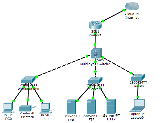
What is a network? This is a set of devices and systems that are connected to each other (logically or physically) and communicate with each other. This could include servers, computers, phones, routers, and so on. The size of this network can reach the size of the Internet, and can consist of only two devices connected by a cable. To avoid porridge, we divide the network components into groups:
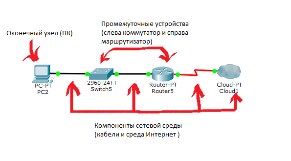
1) Terminal Nodes: Devices that transmit and / or receive any data. These can be computers, phones, servers, some terminals or thin clients, TVs.
2) Intermediate devices: These are devices that connect end nodes with each other. This could include switches, hubs, modems, routers, Wi-Fi access points.
3) Network environments: These are the environments in which direct data transfer occurs. These include cables, network cards, various kinds of connectors, air transmission medium. If it is a copper cable, the data is transmitted using electrical signals. At fiber optic cables, using light pulses. Well, with wireless devices, using radio waves.
Let's see all this in the picture:
At the moment, you just need to understand the difference. Detailed differences will be disassembled later.
Now, in my opinion, the main question: Why do we use the network? There are many answers to this question, but I will highlight the most popular ones used in everyday life:
1) Applications: Using applications, we send different data between devices, open access to shared resources. It can be both console applications and applications with a graphical interface.
2) Network resources: These are network printers, which, for example, are used in the office or network cameras that are watched by security while in remote areas.
3) Storage: Using a server or a workstation connected to the network, a storage is created that is accessible to others. Many people upload their files, videos, pictures there and share them with other users. An example that comes to mind on the go is a google disk, Yandex disk and similar services.
4) Backup: Often, in large companies, use a central server, where all computers copy important files for backup. This is necessary for subsequent data recovery if the original is deleted or damaged. There are a huge number of copying methods: precompression, encoding, and so on.
5) VoIP: IP telephony. It is used everywhere now, as it is simpler, cheaper than traditional telephony and is pushing it out every year.
Of the entire list, most often, many worked with applications. Therefore, we analyze them in more detail. I will diligently choose only those applications that are somehow connected to the network. Therefore, applications such as a calculator or a notebook, I do not take into account.
1) Loaders. These are file managers working via FTP, TFTP. A trivial example is downloading a movie, music, pictures from file sharing sites or other sources. This category also includes backup, which is automatically made by the server every night. That is, these are built-in or third-party programs and utilities that perform copying and downloading. This type of application does not require direct human intervention. It is enough to indicate the place where to save and the download itself will start and end.
Download speed depends on bandwidth. For this type of application, this is not entirely critical. If, for example, a file is downloaded not for a minute, but 10, then there is only a matter of time, and this will not affect the integrity of the file. Difficulties can arise only when we need to make a backup of the system in a couple of hours, and because of a bad channel and, accordingly, low bandwidth, it takes several days. Below are descriptions of the most popular protocols of this group:
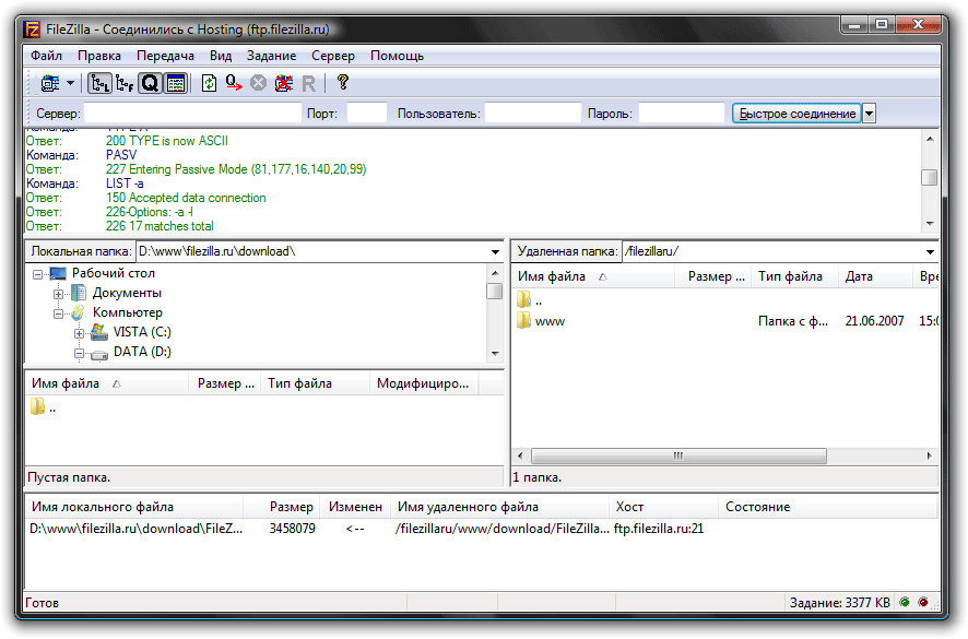
FTP is a standard data connection protocol. Works under the TCP protocol (this protocol will be discussed in detail in the future). The standard port number is 21. Most often used to upload a site to a web hosting and upload it. The most popular application that uses this protocol is Filezilla. Here is the application itself:
TFTP is a simplified version of FTP, which works without a connection, using UDP. It is used to load an image with diskless workstations. Especially widely used by Cisco devices for the same image and backup downloads.
Interactive applications. Applications that allow interactive exchange. For example, the model "man-man". When two people, using interactive applications, communicate with each other or conduct common work. This includes: ICQ, e-mail, a forum in which several experts help people with their questions. Or the man-machine model. When a person communicates directly with the computer. This may be a remote database configuration, network device configuration. Here, in contrast to the bootloaders, it is important that human intervention is permanent. That is, at least one person initiates. Throughput is already more sensitive to latency than downloader applications. For example, with a remote configuration of a network device, it will be hard to configure it if the response from the command is 30 seconds.
Applications in real time. Applications that allow you to transmit information in real time. This group includes IP telephony, streaming systems, and video conferencing. The most sensitive to delays and bandwidth applications. Imagine that you are talking on the phone and what you are saying, the interlocutor will hear after 2 seconds and vice versa, you are from the interlocutor with the same interval. Such communication will also lead to the fact that the voices will disappear and the conversation will be difficult to distinguish, and in a videoconference will turn into a mess. On average, the delay should not exceed 300 ms. This category includes Skype, Lync, Viber (when making a call).
Now let's talk about such an important thing as topology. It is divided into 2 broad categories: physical and logical . It is very important to understand their difference. So the physical topology is what our network looks like. Where are the nodes, what network intermediate devices are used and where they stand, what network cables are used, how they are stretched and which port is plugged in. Logical topology - this is what way the packets will go in our physical topology. That is, physical is how we positioned the devices, and logical is what devices will pass packets.
Now we will look and we will sort types of topology:
1) Topology with a common bus (eng. Bus Topology)
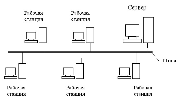
One of the first physical topologies. The bottom line was that all devices were connected to a single long cable and they organized a local network. At the ends of the cable, terminators were required. As a rule - it was a 50 ohm impedance, which was used to prevent the signal from being reflected in the cable. Its advantage was only in the ease of installation. In terms of performance was extremely unstable. If somewhere in the cable there was a break, then the entire network remained paralyzed until the cable was replaced.
2) Ring topology (English Ring Topology)

In this topology, each device is connected to the 2 neighboring ones. Thus creating a ring. Here the logic is such that from one end only the computer receives, and from the other it only sends. That is, the transmission is received around the ring and the next computer plays the role of a signal repeater. Due to this, the need for terminators has disappeared. Accordingly, if somewhere the cable was damaged, the ring was opened and the network became inoperable. To increase resiliency, use a double ring, that is, in each device comes two cables, and not one. Accordingly, if one cable fails, the backup remains to work.
3) Star Topology (eng. Star Topology)
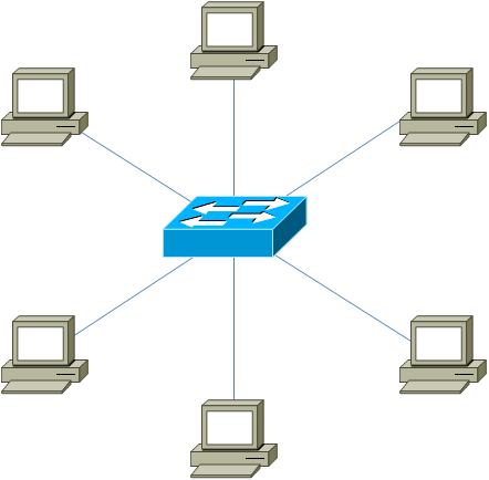
All devices are connected to the central site, which is already a repeater. Nowadays, this model is used in local networks, when several devices are connected to one switch and it is an intermediary in transmission. Here, fault tolerance is significantly higher than in the previous two. When a cable is broken, only one device drops out of the network. All the rest continue to work quietly. However, if the central link fails, the network will become inoperative.
4) Full-connected topology (Full-Mesh Topology)
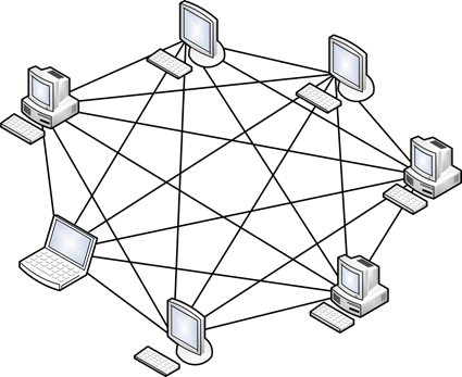
All devices are directly connected to each other. That is, from each to each. This model is probably the most fault-tolerant, since it does not depend on others. But building networks on such a model is difficult and expensive. Since the network, in which at least 1000 computers, will have to connect 1000 cables to each computer.
5) incomplete topology (eng. Partial-Mesh Topology)
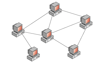
As a rule, its several options. It is similar in structure to a fully connected topology. However, the connection is not built from each to each, but through additional nodes. That is, node A is directly connected only to node B, and node B is connected both with node A and node C. So, in order for node A to send a message to node C, it must first be sent to node B, and node B in turn will send this message to node C. In principle, routers work on this topology. I will give an example from the home network. When you go out of the house to the Internet, you do not have a direct cable to all nodes, and you send the data to your provider, and he already knows where to send this data.
6) Mixed Topology (Eng. Hybrid Topology)
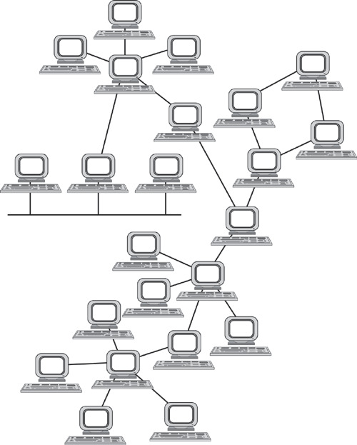
The most popular topology that combines all the topologies above into itself. It is a tree structure that unites all topologies. One of the most fault-tolerant topologies, as if the two sites have a break, then only the connection between them will be paralyzed, and all the other combined sites will work without fail. Today, this topology is used in all medium and large companies.
And the last thing that remains to be seen is network models. At the stage of the birth of computers, the networks did not have uniform standards. Each vendor used its proprietary solutions that did not work with the technologies of other vendors. Of course, it was impossible to leave it that way and it was necessary to invent a common solution. This task was assumed by the international organization for standardization (ISO - International Organization for Standartization). They studied many of the models used at the time, and as a result came up with the OSI model , which was released in 1984. Her problem was only that it was developed for about 7 years. While experts were arguing about how best to make it, other models were modernized and gained momentum. Currently, the OSI model is not used. It is used only as a training network. My personal opinion is that every self-respecting admin should know the OSI model as a multiplication table. Although it is not used in the form in which it is, the working principles of all models are similar to it.
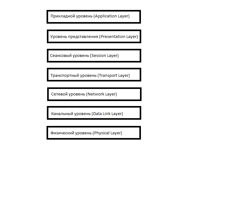
It consists of 7 levels and each level performs a certain role and tasks. Let us examine what each level does upwards:
1) Physical Layer (Physical Layer): determines the method of data transmission, which medium is used (transmission of electrical signals, light pulses or radio), voltage level, coding method of binary signals.
2) Data Link Layer: it takes on the task of addressing within the local network, detects errors, checks data integrity. If you have heard about MAC addresses and the Ethernet protocol, they are located at this level.
3) Network layer (Network Layer): this layer assumes the integration of network segments and the choice of the optimal path (ie, routing). Each network device must have a unique network address on the network. I think many have heard about the IPv4 and IPv6 protocols. These protocols work at this level.
4) Transport Layer: This layer takes over the transport function. For example, when you download a file from the Internet, the file is sent as a segment to your computer. It also introduces the concept of ports, which are needed to indicate the destination to a specific service. At this level, the TCP (with the establishment of the connection) and UDP (without the establishment of the connection) work.
5) Session Layer: The role of this layer in establishing, managing, and breaking the connection between two hosts. For example, when you open a page on a web server, you are not the only visitor on it. And in order to maintain sessions with all users, you need a session level.
6) Presentation Layer: It structures information in a readable form for the application layer. For example, many computers use an ASCII character set table for displaying text information or jpeg format for displaying a graphic image.
7) Application Layer: This is probably the most understandable level for everyone. The usual for us applications work just at this level - e-mail, browsers via HTTP, FTP and the rest.
The most important thing to remember is that you cannot jump from level to level (for example, from application to channel, or from physical to transport). The entire path must pass strictly from the top to the bottom and from the bottom to the top. Such processes are called encapsulation (from top to bottom) and de-encapsulation (from bottom to top). It is also worth mentioning that at each level the information transmitted is called differently.
At the application, presentation, and session levels, the transmitted information is referred to as Protocol Data Units PDUs. In Russian, data blocks are also called, although in my circle they are simply called data).
Information transport level called segments. Although the concept of segments, is applicable only for TCP. For UDP, the concept of a datagram is used. But, as a rule, this distinction is overlooked.
At the network level, they call IP packets or just packets.
And at the channel level - frames. On the one hand, this is all terminology and it does not play an important role in how you will call the transmitted data, but for the exam these concepts are better to know. So, I will give my favorite example, which helped me, in my time, to deal with the process of encapsulation and de-encapsulation:
1) Imagine the situation that you are sitting at your computer at home, and in the next room you have your own local web server. And now you need to download the file from it. You type the address of your website page. You are currently using the HTTP protocol, which works at the application level. The data is packaged and lowered to a lower level.
2) The data obtained resorted to the presentation level. Here this data is structured and presented in a format that can be read on the server. Packed and descended below.
3) At this level, a session is created between the computer and the server.
4) Since this is a web server and reliable connection and control of received data is required, TCP is used. Here we indicate the port to which we will knock and the source port so that the server knows where to send the response. This is necessary in order for the server to understand that we want to go to the web server (standardly, this is port 80), and not to the mail server. We pack and descend further.
5) Here we must indicate to which address to send the packet. Accordingly, we indicate the destination address (let the server address be 192.168.1.2) and the source address (computer address 192.168.1.1). Wrap and descend further.
6) The IP packet goes down and the link layer comes into operation. It adds the physical addresses of the source and destination, which will be described in detail in a subsequent article. Since we have a computer and a server in the local environment, the source address will be the MAC address of the computer, and the destination address will be the MAC address of the server (if the computer and server were on different networks, the addressing would work differently). If at the upper levels a header was added each time, then a trailer is added here, which indicates the end of the frame and the readiness of all the collected data for sending.
7) And already the physical layer converts the received into bits and with the help of electrical signals (if it is a twisted pair), sends it to the server.
The process of de-encapsulation is similar, but with the reverse sequence:
1) At the physical level, electrical signals are received and converted into a clear bit sequence for the data link layer.
2) At the data link layer, the destination MAC address is checked (whether it is addressed to it). If so, then the frame is checked for integrity and no errors, if everything is fine and the data is intact, it passes them to a higher level.
3) At the network level, the destination IP address is checked. And if it is true, data rises above. It is not necessary to go into details now why we have addressing at the channel and network level. This topic requires special attention, and I will explain their difference in detail later. The main thing now is to understand how the data is packed and unpacked.
4) At the transport level, the destination port (not the address) is checked. And according to the port number, it turns out which application or service the data is addressed to. We have a web server and the port number is 80.
5) At this level, a session is established between the computer and the server.
6) The presentation layer sees how everything should be structured and brings information into a readable form.
7) And at this level, applications or services understand what needs to be done.
Much has been written about the OSI model. Although I tried to be as brief as possible and highlight the most important. In fact, a lot has been written about this model on the Internet and in books, but for beginners and those preparing for CCNA, this is enough. Of the questions on the exam for this model can be 2 questions. It is the right place the levels and at what level does a particular protocol work.
As it was written above, the OSI model in our time is not used. While this model was being developed, the TCP / IP protocol stack was becoming increasingly popular. It was much simpler and gained quick popularity.
This is how the stack looks like:
As you can see, it is different from OSI and even changed the name of some levels. In fact, he has the same principle as OSI. But only the top three OSI layers: application, view, and session are combined in TCP / IP into one, called application. — . . OSI: TCP/IP — . TCP/IP DoD (Department of Defence). , . . : « DoD?», . .
, , . IPX/SPX. 80- 90-, TCP/IP. Novell Xerox Network Services Xerox. . IPX/SPX «». , . , 2001 , , IPX/SPX .
, — AppleTalk. , Apple. , OSI, 1984 . Apple TCP/IP.
. Token Ring FDDI — ! Token Ring — , FDDI , Token Ring. , . , .
. , . . , ). - , , , , . Thanks for reading. .
A little offtopic: About a month ago, I passed the CCNA exam (at 980/1000 points) and a lot of material remained for the year of my preparation and training. I first studied at the Cisco Academy for about 7 months, and the remaining time kept notes on all the topics that I had studied. He also advised many guys in the field of network technologies and noticed that many are attacking the same rake, in the form of gaps on some key topics. The other day, a couple of guys asked me to explain what networks are and how to work with them. In this regard, I decided to describe the most key and important things in the most detailed and simple language. Articles will be useful for beginners who have just embarked on the path of learning. But, perhaps, experienced system administrators will emphasize something useful from this. Since I will follow the CCNA program, it will be very useful to those people who are preparing for the surrender. You can keep the articles in the form of cheat sheets and periodically review them. During my studies I took notes on books and periodically read them to refresh my knowledge.
In general, I want to give advice to all beginners. My first serious book was Oliferov's Computer Networks. And it was very hard for me to read it. Not to say that everything was hard. But the moments where it was understood in detail how MPLS or carrier-grade Ethernet works, introduced into a stupor. I read one chapter for several hours and still much remained a mystery. If you understand that some terms do not want to go into your head, skip them and read further, but in no case do not discard the book completely. This is not a novel or epic, where it is important to read chapters to understand the plot. Time will pass and what was previously incomprehensible, in the end it will become clear. Here is pumped "book skill." Each next book is read easier than the previous book. For example, after reading “Computer Networks” by Oliferov, it is easier to read Tanenbaum “Computer Networks” several times and vice versa. Because there are fewer new concepts. Therefore, my advice: do not be afraid to read books. Your efforts in the future will bear fruit. I finish the talk and start writing the article.
')
Here are the topics themselves
1) Basic network terms, OSI network model and TCP / IP protocol stack.
2) Top-level protocols.
3) Protocols of lower levels (transport, network and channel).
4) Network devices and types of cables used.
5) The concept of IP addressing, subnet masks and their calculation.
6) The concept of VLAN, Trunk and VTP and DTP protocols.
7) Spanning Tree Protocol: STP.
8) Channel Aggregation Protocol: Etherchannel.
9) Routing: static and dynamic on the example of RIP, OSPF and EIGRP.
10) Network Address Translation: NAT and PAT.
11) Reservation protocols for the first transition: FHRP.
12) Computer network security and virtual private networks: VPN.
13) Global networks and protocols used: PPP, HDLC, Frame Relay.
14) Introduction to IPv6 configuration and routing.
15) Network management and network monitoring.
PS Perhaps over time, the list will be added.
So let's start with the basic network terms.
What is a network? This is a set of devices and systems that are connected to each other (logically or physically) and communicate with each other. This could include servers, computers, phones, routers, and so on. The size of this network can reach the size of the Internet, and can consist of only two devices connected by a cable. To avoid porridge, we divide the network components into groups:
1) Terminal Nodes: Devices that transmit and / or receive any data. These can be computers, phones, servers, some terminals or thin clients, TVs.
2) Intermediate devices: These are devices that connect end nodes with each other. This could include switches, hubs, modems, routers, Wi-Fi access points.
3) Network environments: These are the environments in which direct data transfer occurs. These include cables, network cards, various kinds of connectors, air transmission medium. If it is a copper cable, the data is transmitted using electrical signals. At fiber optic cables, using light pulses. Well, with wireless devices, using radio waves.
Let's see all this in the picture:
At the moment, you just need to understand the difference. Detailed differences will be disassembled later.
Now, in my opinion, the main question: Why do we use the network? There are many answers to this question, but I will highlight the most popular ones used in everyday life:
1) Applications: Using applications, we send different data between devices, open access to shared resources. It can be both console applications and applications with a graphical interface.
2) Network resources: These are network printers, which, for example, are used in the office or network cameras that are watched by security while in remote areas.
3) Storage: Using a server or a workstation connected to the network, a storage is created that is accessible to others. Many people upload their files, videos, pictures there and share them with other users. An example that comes to mind on the go is a google disk, Yandex disk and similar services.
4) Backup: Often, in large companies, use a central server, where all computers copy important files for backup. This is necessary for subsequent data recovery if the original is deleted or damaged. There are a huge number of copying methods: precompression, encoding, and so on.
5) VoIP: IP telephony. It is used everywhere now, as it is simpler, cheaper than traditional telephony and is pushing it out every year.
Of the entire list, most often, many worked with applications. Therefore, we analyze them in more detail. I will diligently choose only those applications that are somehow connected to the network. Therefore, applications such as a calculator or a notebook, I do not take into account.
1) Loaders. These are file managers working via FTP, TFTP. A trivial example is downloading a movie, music, pictures from file sharing sites or other sources. This category also includes backup, which is automatically made by the server every night. That is, these are built-in or third-party programs and utilities that perform copying and downloading. This type of application does not require direct human intervention. It is enough to indicate the place where to save and the download itself will start and end.
Download speed depends on bandwidth. For this type of application, this is not entirely critical. If, for example, a file is downloaded not for a minute, but 10, then there is only a matter of time, and this will not affect the integrity of the file. Difficulties can arise only when we need to make a backup of the system in a couple of hours, and because of a bad channel and, accordingly, low bandwidth, it takes several days. Below are descriptions of the most popular protocols of this group:
FTP is a standard data connection protocol. Works under the TCP protocol (this protocol will be discussed in detail in the future). The standard port number is 21. Most often used to upload a site to a web hosting and upload it. The most popular application that uses this protocol is Filezilla. Here is the application itself:
TFTP is a simplified version of FTP, which works without a connection, using UDP. It is used to load an image with diskless workstations. Especially widely used by Cisco devices for the same image and backup downloads.
Interactive applications. Applications that allow interactive exchange. For example, the model "man-man". When two people, using interactive applications, communicate with each other or conduct common work. This includes: ICQ, e-mail, a forum in which several experts help people with their questions. Or the man-machine model. When a person communicates directly with the computer. This may be a remote database configuration, network device configuration. Here, in contrast to the bootloaders, it is important that human intervention is permanent. That is, at least one person initiates. Throughput is already more sensitive to latency than downloader applications. For example, with a remote configuration of a network device, it will be hard to configure it if the response from the command is 30 seconds.
Applications in real time. Applications that allow you to transmit information in real time. This group includes IP telephony, streaming systems, and video conferencing. The most sensitive to delays and bandwidth applications. Imagine that you are talking on the phone and what you are saying, the interlocutor will hear after 2 seconds and vice versa, you are from the interlocutor with the same interval. Such communication will also lead to the fact that the voices will disappear and the conversation will be difficult to distinguish, and in a videoconference will turn into a mess. On average, the delay should not exceed 300 ms. This category includes Skype, Lync, Viber (when making a call).
Now let's talk about such an important thing as topology. It is divided into 2 broad categories: physical and logical . It is very important to understand their difference. So the physical topology is what our network looks like. Where are the nodes, what network intermediate devices are used and where they stand, what network cables are used, how they are stretched and which port is plugged in. Logical topology - this is what way the packets will go in our physical topology. That is, physical is how we positioned the devices, and logical is what devices will pass packets.
Now we will look and we will sort types of topology:
1) Topology with a common bus (eng. Bus Topology)
One of the first physical topologies. The bottom line was that all devices were connected to a single long cable and they organized a local network. At the ends of the cable, terminators were required. As a rule - it was a 50 ohm impedance, which was used to prevent the signal from being reflected in the cable. Its advantage was only in the ease of installation. In terms of performance was extremely unstable. If somewhere in the cable there was a break, then the entire network remained paralyzed until the cable was replaced.
2) Ring topology (English Ring Topology)
In this topology, each device is connected to the 2 neighboring ones. Thus creating a ring. Here the logic is such that from one end only the computer receives, and from the other it only sends. That is, the transmission is received around the ring and the next computer plays the role of a signal repeater. Due to this, the need for terminators has disappeared. Accordingly, if somewhere the cable was damaged, the ring was opened and the network became inoperable. To increase resiliency, use a double ring, that is, in each device comes two cables, and not one. Accordingly, if one cable fails, the backup remains to work.
3) Star Topology (eng. Star Topology)
All devices are connected to the central site, which is already a repeater. Nowadays, this model is used in local networks, when several devices are connected to one switch and it is an intermediary in transmission. Here, fault tolerance is significantly higher than in the previous two. When a cable is broken, only one device drops out of the network. All the rest continue to work quietly. However, if the central link fails, the network will become inoperative.
4) Full-connected topology (Full-Mesh Topology)
All devices are directly connected to each other. That is, from each to each. This model is probably the most fault-tolerant, since it does not depend on others. But building networks on such a model is difficult and expensive. Since the network, in which at least 1000 computers, will have to connect 1000 cables to each computer.
5) incomplete topology (eng. Partial-Mesh Topology)
As a rule, its several options. It is similar in structure to a fully connected topology. However, the connection is not built from each to each, but through additional nodes. That is, node A is directly connected only to node B, and node B is connected both with node A and node C. So, in order for node A to send a message to node C, it must first be sent to node B, and node B in turn will send this message to node C. In principle, routers work on this topology. I will give an example from the home network. When you go out of the house to the Internet, you do not have a direct cable to all nodes, and you send the data to your provider, and he already knows where to send this data.
6) Mixed Topology (Eng. Hybrid Topology)
The most popular topology that combines all the topologies above into itself. It is a tree structure that unites all topologies. One of the most fault-tolerant topologies, as if the two sites have a break, then only the connection between them will be paralyzed, and all the other combined sites will work without fail. Today, this topology is used in all medium and large companies.
And the last thing that remains to be seen is network models. At the stage of the birth of computers, the networks did not have uniform standards. Each vendor used its proprietary solutions that did not work with the technologies of other vendors. Of course, it was impossible to leave it that way and it was necessary to invent a common solution. This task was assumed by the international organization for standardization (ISO - International Organization for Standartization). They studied many of the models used at the time, and as a result came up with the OSI model , which was released in 1984. Her problem was only that it was developed for about 7 years. While experts were arguing about how best to make it, other models were modernized and gained momentum. Currently, the OSI model is not used. It is used only as a training network. My personal opinion is that every self-respecting admin should know the OSI model as a multiplication table. Although it is not used in the form in which it is, the working principles of all models are similar to it.
It consists of 7 levels and each level performs a certain role and tasks. Let us examine what each level does upwards:
1) Physical Layer (Physical Layer): determines the method of data transmission, which medium is used (transmission of electrical signals, light pulses or radio), voltage level, coding method of binary signals.
2) Data Link Layer: it takes on the task of addressing within the local network, detects errors, checks data integrity. If you have heard about MAC addresses and the Ethernet protocol, they are located at this level.
3) Network layer (Network Layer): this layer assumes the integration of network segments and the choice of the optimal path (ie, routing). Each network device must have a unique network address on the network. I think many have heard about the IPv4 and IPv6 protocols. These protocols work at this level.
4) Transport Layer: This layer takes over the transport function. For example, when you download a file from the Internet, the file is sent as a segment to your computer. It also introduces the concept of ports, which are needed to indicate the destination to a specific service. At this level, the TCP (with the establishment of the connection) and UDP (without the establishment of the connection) work.
5) Session Layer: The role of this layer in establishing, managing, and breaking the connection between two hosts. For example, when you open a page on a web server, you are not the only visitor on it. And in order to maintain sessions with all users, you need a session level.
6) Presentation Layer: It structures information in a readable form for the application layer. For example, many computers use an ASCII character set table for displaying text information or jpeg format for displaying a graphic image.
7) Application Layer: This is probably the most understandable level for everyone. The usual for us applications work just at this level - e-mail, browsers via HTTP, FTP and the rest.
The most important thing to remember is that you cannot jump from level to level (for example, from application to channel, or from physical to transport). The entire path must pass strictly from the top to the bottom and from the bottom to the top. Such processes are called encapsulation (from top to bottom) and de-encapsulation (from bottom to top). It is also worth mentioning that at each level the information transmitted is called differently.
At the application, presentation, and session levels, the transmitted information is referred to as Protocol Data Units PDUs. In Russian, data blocks are also called, although in my circle they are simply called data).
Information transport level called segments. Although the concept of segments, is applicable only for TCP. For UDP, the concept of a datagram is used. But, as a rule, this distinction is overlooked.
At the network level, they call IP packets or just packets.
And at the channel level - frames. On the one hand, this is all terminology and it does not play an important role in how you will call the transmitted data, but for the exam these concepts are better to know. So, I will give my favorite example, which helped me, in my time, to deal with the process of encapsulation and de-encapsulation:
1) Imagine the situation that you are sitting at your computer at home, and in the next room you have your own local web server. And now you need to download the file from it. You type the address of your website page. You are currently using the HTTP protocol, which works at the application level. The data is packaged and lowered to a lower level.
2) The data obtained resorted to the presentation level. Here this data is structured and presented in a format that can be read on the server. Packed and descended below.
3) At this level, a session is created between the computer and the server.
4) Since this is a web server and reliable connection and control of received data is required, TCP is used. Here we indicate the port to which we will knock and the source port so that the server knows where to send the response. This is necessary in order for the server to understand that we want to go to the web server (standardly, this is port 80), and not to the mail server. We pack and descend further.
5) Here we must indicate to which address to send the packet. Accordingly, we indicate the destination address (let the server address be 192.168.1.2) and the source address (computer address 192.168.1.1). Wrap and descend further.
6) The IP packet goes down and the link layer comes into operation. It adds the physical addresses of the source and destination, which will be described in detail in a subsequent article. Since we have a computer and a server in the local environment, the source address will be the MAC address of the computer, and the destination address will be the MAC address of the server (if the computer and server were on different networks, the addressing would work differently). If at the upper levels a header was added each time, then a trailer is added here, which indicates the end of the frame and the readiness of all the collected data for sending.
7) And already the physical layer converts the received into bits and with the help of electrical signals (if it is a twisted pair), sends it to the server.
The process of de-encapsulation is similar, but with the reverse sequence:
1) At the physical level, electrical signals are received and converted into a clear bit sequence for the data link layer.
2) At the data link layer, the destination MAC address is checked (whether it is addressed to it). If so, then the frame is checked for integrity and no errors, if everything is fine and the data is intact, it passes them to a higher level.
3) At the network level, the destination IP address is checked. And if it is true, data rises above. It is not necessary to go into details now why we have addressing at the channel and network level. This topic requires special attention, and I will explain their difference in detail later. The main thing now is to understand how the data is packed and unpacked.
4) At the transport level, the destination port (not the address) is checked. And according to the port number, it turns out which application or service the data is addressed to. We have a web server and the port number is 80.
5) At this level, a session is established between the computer and the server.
6) The presentation layer sees how everything should be structured and brings information into a readable form.
7) And at this level, applications or services understand what needs to be done.
Much has been written about the OSI model. Although I tried to be as brief as possible and highlight the most important. In fact, a lot has been written about this model on the Internet and in books, but for beginners and those preparing for CCNA, this is enough. Of the questions on the exam for this model can be 2 questions. It is the right place the levels and at what level does a particular protocol work.
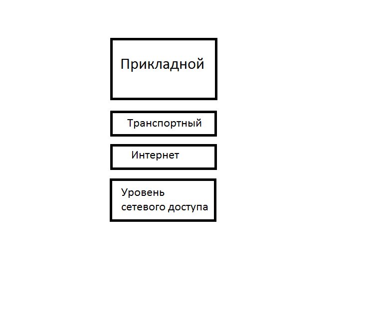
As it was written above, the OSI model in our time is not used. While this model was being developed, the TCP / IP protocol stack was becoming increasingly popular. It was much simpler and gained quick popularity.
This is how the stack looks like:
As you can see, it is different from OSI and even changed the name of some levels. In fact, he has the same principle as OSI. But only the top three OSI layers: application, view, and session are combined in TCP / IP into one, called application. — . . OSI: TCP/IP — . TCP/IP DoD (Department of Defence). , . . : « DoD?», . .
, , . IPX/SPX. 80- 90-, TCP/IP. Novell Xerox Network Services Xerox. . IPX/SPX «». , . , 2001 , , IPX/SPX .
, — AppleTalk. , Apple. , OSI, 1984 . Apple TCP/IP.
. Token Ring FDDI — ! Token Ring — , FDDI , Token Ring. , . , .
. , . . , ). - , , , , . Thanks for reading. .
Source: https://habr.com/ru/post/307252/
All Articles