Do not Perseids uniform or Model flash satellite with their own hands
Hi, Habr! After colorful meteor showers, we smoothly move to astronomical autumn. This year, it foreshadows us a lunar eclipse, a conjunction of Venus and Jupiter , as well as flights of bright man-made satellites. My today's story is about how to model the reflection of light from such satellites, and what is unusual awaits us this October.
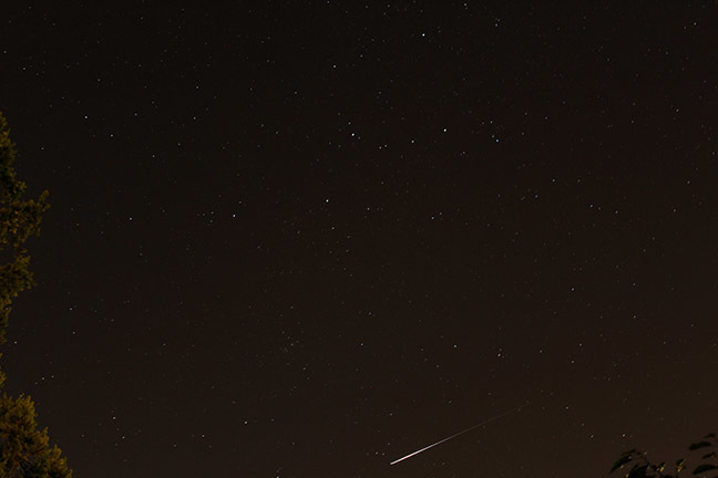
Iridium flash , the first photo with my own hands - I pointed the wrong way, the shutter opened late, the horizon filled up :)
How it all began
In the spring, a post about Lighthouse satellite appeared on Hiktaims. This is a Kubsat with a size of 30x10x10 cm, the main task of which, after going into orbit, is to open a mirror film that will reflect sunlight towards the Earth. According to the authors, this should make Beacon one of the brightest satellites in the night sky. The piquancy is added by the fact that Mayak is the first satellite in Russia for which funds were raised by crowdfunding, and very successfully.

( picture from here )
Habr, undoubtedly, is still a cake: in the comments there was a lively discussion about the feasibility of the project, to which the developers were also connected. And if everything was all right with the design of the satellite, then the statements about the “brightest star in the sky” were very surprised. For example, due to the fact that the film mirror is rarely good. Or because the satellite must spin around its axis at a speed of one revolution per second — then the speed of the sunbeam on the Earth turns out to be enormous, and the flashes must be too short. The developers admitted that they really have problems with the calculation of reflections, and offered to those who wish to help them with this.
The first analytical calculation proposed Quiensabe . ( His post with not very optimistic results was published on GT, but it was removed due to inaccurate reference to crowdfunding - however, that’s another story. ) Such a calculation gave an adequate assessment, but could not take into account the mass of factors - the curvature of the Earth’s surface, the change flash brightness as the rotation of the mirror and other things. A neat numerical model was needed, which counts the brightness of the reflection with a small time step depending on the relative position of the satellite, the observer, the Sun and everything else.
The task did not seem too complicated - it just needed to carefully understand all the geometry and not mess up anything. Motivated and the ability to find something such cosmic. And, of course, the joy of writing your own bike is priceless.
( There will be a lot of mathematics next. The results start here , well, quite tl; dr - here . )
Algorithm
The main task of the model is to calculate the maximum flash brightness for the given satellite parameters and the given observer position on Earth. In this case, the prediction of flares for a few days goes into the background - for this there is, for example, heavens-above.com . It would be logical to take one satellite pass over the observer, and already for him to calculate the reflection brightness with a small time step. After that, by varying the initial parameters, it will be possible to calculate the maximum possible flash brightness.
So, the first step: to see the flash, it is necessary that the satellite: a) flew over the horizon and b) was not in the shadow of the Earth. Step two: if these conditions are met, you can begin to consider the brightness of the flash. Yes, it is very likely that the satellite will rotate - in this case, the flashes may be periodic. (Flashing satellite!) Therefore, in general, the third step is needed - to search for individual flashes separated by intervals of darkness. Lines up the logic of the program, which implements three functions:
- The first function counts the coordinates of the satellite and the observer during one revolution with a large time step (1-5 seconds) and checks at which points the satellite is visible above the horizon and is not in the shade. If the satellite appears above the horizon, the function calculates the time intervals when it is visible, and transmits them to the second function.
- The second function works with a small time step (0.001 - 1 s) and at each step calculates the brightness of the flash, which the observer sees.
- The third function is the most non-cosmic one. She finds the individual flashes in the results of the second function and considers their parameters: brightness, duration, maximum transit time, and so on.
Physical model
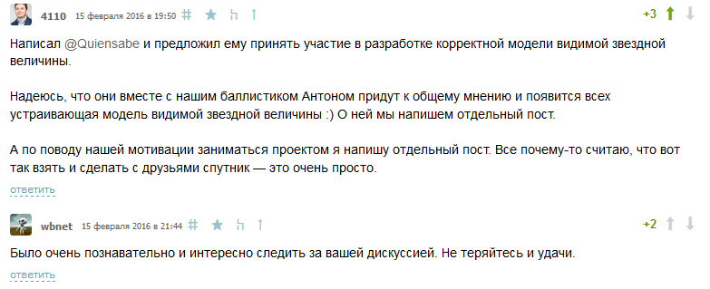
We will model the task in the ECI (Earth-centered inertial) reference system - its beginning coincides with the center of the Earth, the Z axis is directed to the north pole, and the Sun is in the XZ plane.
Why ECI? Because the Sun is motionless in it, the observer rotates with the Earth around the Z axis, and the satellite orbit does not change its position in space. This means that the coordinates of both the satellite and the observer are easily parameterized through the angles. Details - under the spoiler.
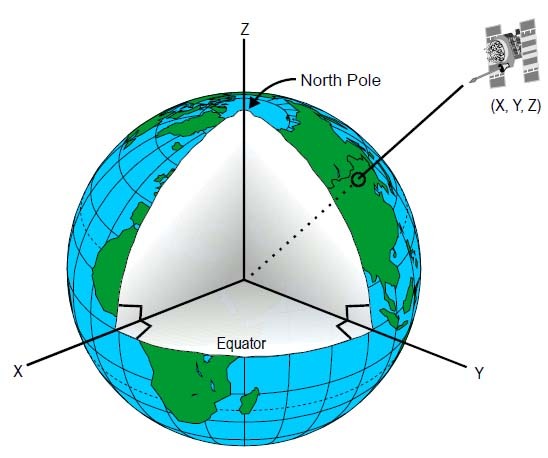
The coordinates of the observer are given by the latitude of fi obs and the current longitude of theta obs .
In essence, theta obs is local time: noon corresponds to theta obs = 0, and midnight - theta obs = 180. You also need to know the local time at the initial time theta obs0 and the speed of the Earth’s rotation around its axis. Then the coordinates of the observer in ECI are expressed as:

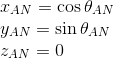
The satellite orbit to facilitate the calculations can be considered circular. In this case, it can be set with three parameters: radius R orb , inclination fi and longitude of the ascending node theta AN . The ascending node is the point at which the orbit crosses the equator towards the north.

Gravity, heartless you with . Since the orbit is circular, the satellite moves along it with a constant angular velocity
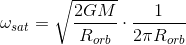
Now that we know all this, the position of the satellite in orbit is easy to parameterize through the alpha angle:

Here dir AN and dir B are the directions to the ascending node and the highest point of the orbit, which are considered simple trigonometry:

The sun. The chip of the ECI reference system is that the Sun is always in the XZ plane. Depending on the time of year, it changes position: when summer is in the northern hemisphere, the sun is above the Z axis, and in the winter - vice versa. We are not interested in the position of the Sun itself, but in the direction to it. Rather, from him, that is, along the direction of movement of the sun's rays. In the pictures it is called k sun .
Did you count the coordinates? Now we need to check whether the satellite is visible above the horizon - otherwise it is meaningless to consider something. This is determined by the co-direction of the vectors from the observer to the satellite - dir sat_obs and to the zenith of dir obs : if their scalar product is positive, then the satellite is somewhere above us.
If the satellite is above the horizon, then you need to know its coordinates in the sky . To do this, the direction to the satellite must be projected onto the plane of the observer. The observer's plane is set by vectors north dir nord and west dir west . The first is through the direction to the zenith and the north pole of the Earth d NP , and already along it and the direction to the zenith the vector to the west is calculated.

Now we need to check if the satellite is not in the shadow of the Earth (otherwise there will obviously be no reflection). From the picture below it is easy to understand that the satellite is in the shadow, if two conditions are fulfilled simultaneously:
- the angle between k sun and dir sat (vector per satellite) is acute;
- d <R
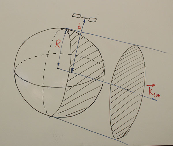
In a similar way, it is necessary to check that the observer is in the shade, that is, he is now in the night. It’s not easy to see a satellite in the sunlight, although day astronomy undoubtedly also has its own charm.
Finally, if the satellite is illuminated by the Sun and is somewhere above us, it remains to calculate the brightness of the flash. More precisely, its apparent magnitude , which shows brightness compared to other stars. The magnitude scale is logarithmic: it is defined as
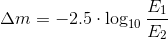
that is, a change in brightness by 100 times corresponds to a change in magnitude by 5 units. It also shows that the magnitude scale has been inverted: smaller values correspond to brighter objects. For example, the magnitude of Arcturus and Vega - the brightest stars of the Northern Hemisphere - is +0.0, Sirius - -1.7, but Venus reaches -4.6 magnitude. The eye distinguishes stars up to +6 magnitude, although in large cities the illumination does not allow to see something brighter than +4.
To calculate the stellar magnitude, you need to know the brightness, or rather the illumination - that is, the power of the light flux passing through a unit of area. It is measured in W / m 2 or in lux, that is, the physical meaning of the illumination is how bright the surface will be. From the definition it follows that the illumination does not depend on the area. Therefore, observation with the naked eye, a camera or a telescope will give the same result of measuring the magnitude.
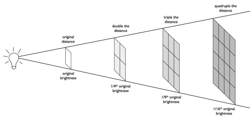
How to calculate the illumination, which creates a reflection from the satellite? First of all, the power of the reflected light (that is, how many photons are reflected from the satellite per second) is found by multiplying the area of the mirror by the illumination created by the Sun. One should not forget that the mirror can be at an angle to the sun's rays. And also about the fact that the mirror is non-uniform and reflects light into a large solid angle - the “hare” on the surface of the Earth will be extended, and we can be far from its center. Finally, the illumination depends quadratically on the distance to the satellite - the farther the satellite is, the less light will reach the observer. The final expression for light is:

where E orbit is the illumination created by the Sun on the Earth’s orbit, the second factor is the area of the mirror at an angle to the sun’s rays, the third is the fraction of the solid angle that the observer sees, and the fourth is the quadratic dependence on the distance to the satellite.
By comparing this number with the illuminance corresponding to a zero magnitude (2.5 ∙ 10 -8 W / m 2 ), we find the magnitude of the satellite.
Whether we see a flash or not is determined by the position of the mirror . It is convenient to set it by the normal vector n mir : this makes it easy to calculate the direction of the reflected beam according to the good old rule about the angle of incidence equal to the angle of reflection:

Simply and easily? By no means! In practice, it is faster to consider how the mirror should be positioned so that at a given position of the satellite and the observer the reflection would fall directly on the observer. And then compare with the current position of the mirror. The advantage of this approach is that it allows you to change the time step. As long as the mirror is far from the optimal position, the step can be increased - there will be no flash anytime soon. If the flash has already begun, then the time step must be reduced to calculate it with the maximum resolution.
Finally, the satellite rotates, and with it the mirror rotates . Therefore, it is convenient to decompose the normal to the mirror n mir into two components — parallel and perpendicular to the axis of rotation of the satellite d mir . The first one remains motionless, the second one precesses - the mathematics of this is exactly the same as the motion of the satellite in orbit.
Code
The code is written in the lab. As I described above, it is divided into three functions, which are in turn called by the main calc_one script. In the main script, constants, initial conditions and simulation parameters are set, which are passed to the functions via the param structure as follows:
% satellite orbit param.incl_sat = 97.75; % inclination, deg (ISS: 51.6, SSO for 600 km: 97.75) param.theta_asc = -7.5; % longitude of the ascending node, deg param.alpha_sat_0 = 0; % angle between AN and the sat in the plane of orbit at t=0, deg param.h_orbit = 600 * 1E3; % orbit height, m %%%%%%%%%%%%%%%%%% SIMULATION PARAMETERS %%%%%%%%%%%%%%%%%%%%%%%%%% % world param.rad_earth = 6400 * 1E3; % Earth radius, m param.GM = 6.67*1E-11 * 5.972*1E24; % grav. constant times Earth mass, m^3/s^2 param.omega_obs = 1/(60*60*24); % Earth angular velocity, turns/s param.k_sun = [-0.99, 0, 0.16]; % sunlight wavevector (22 Jun: [-0.92,0,-0.4]; 21 Dec: [-0.92,0,0.4], 15 Oct: [-0.99,0,0.16]) param.atmosphere_transmission = 0.7; % atmosphere transmission param.flux_sun = 1367; % Sun irradiant flux on the Earth orbit, W/m^2 param.flux_m0 = 2.5*1E-8; % flux corresponding to the apparent magnitude = 0, W/m^2 param.min_m = 6; % minimal visible apparent magnitude % observer param.phi_obs = 55.75; % latitude, deg (Moscow: 55.75) param.theta_obs_0 = 170; % longitude, deg (noon: 0, midnight: 180) % satellite orbit param.incl_sat = 97.75; % inclination, deg param.theta_asc = -7.5; % longitude of the ascending node, deg param.alpha_sat_0 = 0; % angle between AN and the sat in the plane of orbit at t=0, deg param.h_orbit = 600 * 1E3; % orbit height, m % satellite mirror param.omega_rot = 1; % rotation speed of the satellite, turns/s param.d_rot = [0 0.7 1]; % rotation axis of the satellite param.n_mirror_0 = [1 0 0]; % normal to the mirror at t=0 param.gauss_w = 17.2; % divergence angle of a normal distrubution, deg param.sq_mirror = 3.8; % mirror square, m^2 % simulation parameters param.dt1 = 1; % time step if the satellite is below horizon or in the shadow, s param.dt2 = 1; % same if satellite is above horizon, but reflection is far away param.dt3 = 1 * 1E-2; % same if satellite is above horizon, reflection is close param.dt4 = 5 * 1E-3; % same if reflection is seen param.frame_duration = 0.03; % exposition time of a camera/eye, s The first function fn_pass counts the satellite coordinates and searches for a single span above the horizon. First, it calculates any auxiliary values (the direction to the North Pole, the speed of rotation of the satellite, and so on).
% calculate some aux values rad_orbit = rad_earth + h_orbit; % radius of the orbit from the center of Earth r_np = [0 0 rad_earth]; % coordinates of the North pole dir_an = [cosd(theta_asc), sind(theta_asc), 0]; % direction on the acsending node dir_b = [-sind(theta_asc)*cosd(incl_sat),... cosd(theta_asc)*cosd(incl_sat), sind(incl_sat)]; % direction on the highest point of the sat omega_sat = sqrt(2*GM/rad_orbit)/(2*pi*rad_orbit); % satellite angular velocity on the orbit, s^-1 dir_obs_z = sind(phi_obs); % z-coordinate of the observer, does not change After that, the while-loop in time is started with a constant step equal to 1 second. The condition for exiting the cycle is the satellite leaving the horizon (or two satellite turns without a single appearance above the horizon, which is unrealistic in low orbits). In the cycle, the coordinates of the observer and the satellite are calculated sequentially:
% coordinates of the observer theta_obs = mod(theta_obs_0 + 360*omega_obs*current_time, 360); dir_obs = [cosd(phi_obs)*cosd(theta_obs), cosd(phi_obs)*sind(theta_obs), dir_obs_z]; r_obs = rad_earth * dir_obs; % coordinates of the satellite theta_sat = mod(alpha_sat_0 + 360*omega_sat*current_time, 360); dir_sat = cosd(theta_sat)*dir_an + sind(theta_sat)*dir_b; r_sat = rad_orbit*dir_sat; % vector from the satellite to the observer r_sat_obs = r_obs-r_sat; dir_sat_obs = fn_norm(r_sat_obs); it is checked that the satellite is above the horizon and its coordinates are calculated in the sky:
% CHECK1: check if the satellite is above the horizon if fn_dot(dir_obs, dir_sat_obs) < 0 % basis on the skychart r_obs_np = r_np - r_obs; % vector from the observer to the North pole dist_obs_np = sqrt(sum(r_obs_np.^2)); cos_angle_obs_np = fn_dot(r_obs_np, -dir_obs)/dist_obs_np; dir_nord = r_obs_np + cos_angle_obs_np*dist_obs_np*dir_obs; dir_nord = fn_norm(dir_nord); % vector to the nord dir_west = fn_cross(dir_obs, dir_nord); dir_west = fn_norm(dir_west); % vector to the west % coordinates of the satellite on the sky chart pass_path.alt(pass_step,1) = 90 - acosd(fn_dot(-dir_sat_obs, dir_obs)); map_proj_nord = fn_dot(-dir_sat_obs, dir_nord); map_proj_west = fn_dot(-dir_sat_obs, dir_west); pass_path.azimuth(pass_step,1) = mod(-atan2d(map_proj_west, map_proj_nord), 360); and, finally, it is checked whether the satellite is in the shadow:
% CHECK 2: check that the satellite is not in the shadow cos_angle_sat_ksun = fn_dot(dir_sat,k_sun); dist_sat_ksun = rad_orbit*sqrt(1-cos_angle_sat_ksun^2); % distance from the sat to the central axis of shadow if (dist_sat_ksun > rad_earth) % satellite is not in the shadow All data is stored in the pass_path structure, which the function returns. But before that you need to find all the intervals during which the satellite is above the horizon and illuminated by the Sun - they will be needed for the second function to work.
% STEP 2: if the pass was above horizon, % select the regions when sat is above horizon and not in shadow pass_path.reflection_intervals = []; if isempty(pass_path.time) == 0 flag_in_shadow = 1; num_regions_not_in_shadow = 0; for counter_step = 1:size(pass_path.time,1) if pass_path.in_shadow(counter_step) == 0 % satellite is not in shadow if flag_in_shadow == 0 % sat is still not in shadow else % sat was in shadow and just went out of it flag_in_shadow = 0; num_regions_not_in_shadow = num_regions_not_in_shadow + 1; pass_path.reflection_intervals(num_regions_not_in_shadow,1) = pass_path.time(counter_step); end else % satellite is in shadow if flag_in_shadow == 0 % sat was not in shadow and just went into it flag_in_shadow = 1; pass_path.reflection_intervals(num_regions_not_in_shadow,2) = pass_path.time(counter_step); else % sat is still in shadow end end end % if at the end sat was still not in shadow, % time of the end of the last interval will be time of the last % point above the horizon if flag_in_shadow == 0 pass_path.reflection_intervals(num_regions_not_in_shadow,2) = pass_path.time(counter_step); end end The intervals are stored in the pass_path.reflection_intervals in the Nx2 array, where N is the number of visibility intervals, 2 numbers are the time of the beginning and end of the visibility interval. Now the pass_path structure is returned to the main script, from where the second function is called.
The second function fn_reflection works only at intervals where the satellite is above the horizon and illuminated by the sun. At each step (which may be shorter than one second), he also calculates the coordinates of the observer and the satellite, after which he checks whether the mirror is close to the optimal position:
% CHECK 3: if angle (d_rot, n_opt) is close to angle (d_rot, n_mir0), proceed % this means that geometry can in principle give a reflection if (angle_drot_nopt > (angle_drot_nmirror-angle_div))... && (angle_drot_nopt < (angle_drot_nmirror+angle_div)) % current orientation of the mirror n_mir = n_mir_parallel... + n_mir_perp0*cosd(360*omega_rot*current_time)... + n_mir_perp1*sind(360*omega_rot*current_time); % angle between current orientation of the mirror and n_opt angle_nmir_nopt = acosd(fn_dot(n_mir, n_opt)); % CHECK 4: if n_mir is close to n_opt, proceed and calculate the reflection if angle_nmir_nopt < angle_div As can be seen from the code, the location of the mirror is checked by two parameters - azimuth ( CHECK 3 ) and radial ( CHECK 4 ) angles with respect to the axis of rotation of the satellite. The trick is that the radial angle changes as the satellite rotates. But the azimuth is not!
Therefore, first it makes sense to check whether the azimuth angle is close to the optimal position. If not, then nothing will help in the near future. If so, then you can calculate the radial angle, and at the same time reduce the time step.
Finally, if the mirror is close to the optimal position, then the illumination created by the sunbeam can also be calculated. Well, the magnitude at the same time
% calculate the angle between the direction on the observer % and direction of the main reflection cos_angle_nmir_ksun = fn_dot(n_mir, -k_sun); k_refl = 2*cos_angle_nmir_ksun*n_mir + k_sun; cos_angle_refl_obs = abs(fn_dot(k_refl, dir_sat_obs)); angle_refl_obs = acosd(cos_angle_refl_obs); % flux at the observer's place refl_fraction = 2/(pi*degtorad(gauss_w)^2) * exp (-2*angle_refl_obs^2/gauss_w^2); % now it is Gaussian int_reflection = flux_sun * sq_mirror * cos_angle_nmir_ksun; flux = max (int_reflection * refl_fraction ... * atmosphere_transmission / distance^2, flux_min); % W/m^2 It can be seen that if the brightness is too low (dimmer than +6), then the result will be +6. This means that we will not see anything. All results are written to the pass structure, which the function returns.
The third function fn_flares is the simplest: it counts flashes, their maximum brightness, duration and location in the sky. It is really primitive, but long, so I put it under the spoiler.
function pass = fn_flares(pass, param) % this functions counts the flares into the 'pass' structure % summarizes data about their magnitudes, durations, etc. % and saves them in 'pass.flares' field % initialization before the main loop counter_flare = 0; flare_is_now = 0; clear flares flares = struct('time',[],'dist',[],'alt',[],'azimuth',[],'inst_magn',[],'vis_magn',[],'dur',[]); % main loop for step = 1:length(pass.time) if pass.magnitude(step) < param.min_m % flare is present now if flare_is_now == 0 % flare just began flare_is_now = 1; counter_flare = counter_flare + 1; clear current_flare current_flare.time_beg = pass.time(step); % integrate the energy of the flare, [J/m^2] if step < length(pass.time) current_flare.energy = pass.flux(step)*... (pass.time(step+1) - pass.time(step)); else % this was the last data point, nothing to add end % create field 'current_flare.brightest' % with the data about the brightest point of the flare current_flare.brightest.magn = pass.magnitude(step); current_flare.brightest.time = pass.time(step); current_flare.brightest.azimuth = pass.azimuth(step); current_flare.brightest.alt = pass.alt(step); current_flare.brightest.distance = pass.distance(step); else % flare still goes on % increment the energy of the flare if step < length(pass.time) current_flare.energy = current_flare.energy + pass.flux(step)*... (pass.time(step+1) - pass.time(step)); else % this was the last data point, nothing to add end % if here flare is brighter, renew the data about the brightest point if pass.magnitude(step) < current_flare.brightest.magn current_flare.brightest.magn = pass.magnitude(step); current_flare.brightest.time = pass.time(step); current_flare.brightest.azimuth = pass.azimuth(step); current_flare.brightest.alt = pass.alt(step); current_flare.brightest.distance = pass.distance(step); end end else % no flare now if flare_is_now == 0 % still no flare else % flare just ended, sum up the results flare_is_now = 0; current_flare.time_end = pass.time(step-1); current_flare.duration = current_flare.time_end - current_flare.time_beg; if current_flare.duration > param.frame_duration % if the flare is long, we can see it directly current_flare.vis_magn = current_flare.brightest.magn; else % if the flare is short, one should divide its energy % over the exposure time of an eye/camera to get the % apparent magnitude current_flare.vis_magn = ... min(-2.5*log10(current_flare.energy/param.frame_duration/param.flux_m0), param.min_m); end % save the data in the 'flares' structure flares.time(counter_flare,1) = current_flare.brightest.time; flares.dist(counter_flare,1) = current_flare.brightest.distance; flares.azimuth(counter_flare,1) = current_flare.brightest.azimuth; flares.alt(counter_flare,1) = current_flare.brightest.alt; flares.inst_magn(counter_flare,1) = current_flare.brightest.magn; flares.vis_magn(counter_flare,1) = current_flare.vis_magn; flares.dur(counter_flare,1) = current_flare.duration; end end end % return the result flares.num_of_flares = counter_flare; pass.flares = flares; end One problem appears here. If the flash is very short, then the total number of photons caught in the eye can be low even if the instant brightness was high. Then the apparent brightness of the flash will be much less than the maximum.
What does “short flash” mean? Obviously, one that is shorter than the exposure time of the camera. And if we observe it with an eye? What to consider the exposure of the eye, I did not have a clue, so I asked Meklon . He told a lot of interesting things - but it boiled down to the fact that the eye works sooo hard, his sensitivity is highly nonlinear, and therefore a clear answer to the question cannot be given. Even approximately. As a result, it was decided to choose a more or less meaningful number - I chose 30 ms, which corresponds to about 30 frames per second.
So, if the flash turns out to be shorter than the exposure time, then its duration is rounded up to the exposure time, the total amount of light remains unchanged, well, the brightness, respectively, decreases. For example, if in reality a flash lasts 10 ms and during this time 3000 photons arrived, then its momentary “brightness” is 300 photons / ms. We will see that it lasted 30 ms with a “brightness” of 100 photons / ms — 3 times less than the instant one.
Finally, the main calc_one script first calls the first fn_pass function, and if the satellite is visible above the horizon and is not in the shade, it considers the brightness of the reflections as the fn_reflection function and the flash parameters with the fn_flares function:
% calculate trajectory of the pass pass_path = fn_pass(param); % proceed if the satellite is above the horizon and not always in shadow if isempty(pass_path.reflection_intervals) == 0 % calculate the reflections and magnitudes of flares pass = fn_reflection(param, pass_path.reflection_intervals); pass = fn_flares(pass, param); end Optimization
I have already mentioned the first optimization technique: this is a variable time step. The fn_pass function works with a large step (1 s) - to check whether the satellite is visible above the horizon, this is more than enough. But the fn_reflection function has three possible time steps: the smallest (up to 1 ms) is needed to calculate the flash profile, the other two - when the flash is not visible, but it may soon appear. They are defined in the structure with parameters:
param.dt1 = 1; % time step if the satellite is below horizon or in the shadow, s param.dt2 = 1; % same if satellite is above horizon, but reflection is far away param.dt3 = 1 * 1E-2; % same if satellite is above horizon, reflection is close param.dt4 = 5 * 1E-3; % same if reflection is seen The second point is connected with built-in Matlab functions. They were conceived to be universal - for example, the same cosine can be considered from both real and complex numbers, both single and as part of arrays. Naturally, for this versatility, one has to check the input parameters. In the case of simple functions such as scalar product, this test may take longer than the actual mathematics:
function c = dot(a,b,dim) if isinteger(a) || isinteger(b) error(message('MATLAB:dot:integerClass')); end % Special case: A and B are vectors and dim not supplied if ismatrix(a) && ismatrix(b) && nargin<3 if min(size(a))==1, a = a(:); end if min(size(b))==1, b = b(:); end end; % Check dimensions if any(size(a)~=size(b)), error(message('MATLAB:dot:InputSizeMismatch')); end if nargin==2, c = sum(conj(a).*b); else c = sum(conj(a).*b,dim); end In our code, most often, just vector and scalar products are called, as well as the normalization of a vector. Therefore, it makes sense to write their own functions for them without checks - because all the vectors are obviously three-dimensional, and their components are real:
function c = fn_dot(a, b) c = a(1)*b(1) + a(2)*b(2) + a(3)*b(3); end After that, the computation speed has approximately doubled.
In general, there is such a thing as anonymous functions in the matlab. The idea is to declare a function directly in the text of another function, without occupying an additional file. It is argued that they make the code more readable and faster than individual functions.
It turned out that in fact the opposite is true. When I tried to declare scalar and vector products as anonymous functions, the calculations took much longer. In the subtleties of the work of the matlab compiler, I am not strong, so it would be great if someone could explain what is happening.
The code can be found on the githaba . The calculation of the flashes was checked at Iridium and gave meaningful results - the brightness of the flashes was about -9 magnitude.
Lighthouse
Satellite "Mayak" is scheduled to launch this October into a circular orbit with a height of 600 km. In central Russia, it will be best seen from about 22:00 to 02:00 local time. Beacon film mirrors reflect light much worse than the Iridium antennas, but they surpass them in area.
| Parameter | Value |
|---|---|
| Orbit height | 400 - 600 km |
| Orbit inclination | 97.7 ° |
| Direction to ascending node | -7.5 ° |
| Mirror area | 3.8 m 2 |
| Reflection divergence (1σ) | 17.2 ° |
| Rotational speed | unknown (expected 0.5 - 1 rps) |
| Rotation axis orientation | unknown |
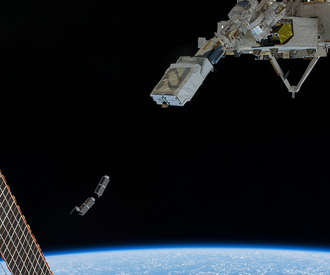
After entering the orbit, the satellite should open the mirrors and spin at a speed of about 1 revolution per second. The problem is that the direction of the twist axis is not known in principle - there are no orientation systems or telemetry on the satellite. A twist is added to all this when the cube is separated from the carrier. Here, for example, two Cubsat launched from the ISS; it is evident that immediately after launching, they already rotate in different ways:
It remains to specify the random direction of the axis of rotation and orientation of the mirror in the calc_one script and see if the observer will see the satellite fly:
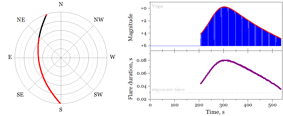
Wow, something is visible! On the left - the trajectory of the satellite in the Moscow sky, at about 11 o'clock in the evening. The red dots are visible flashes of the satellite, the black line is the satellite in the shadow of the Earth and is not visible. The graphs on the right are the brightness of the flashes (above) and their duration (below) depending on the time. It can be seen that the flashes are bright, but short. And judging by the abundance of points, there are really a lot of them (the script counted 330):
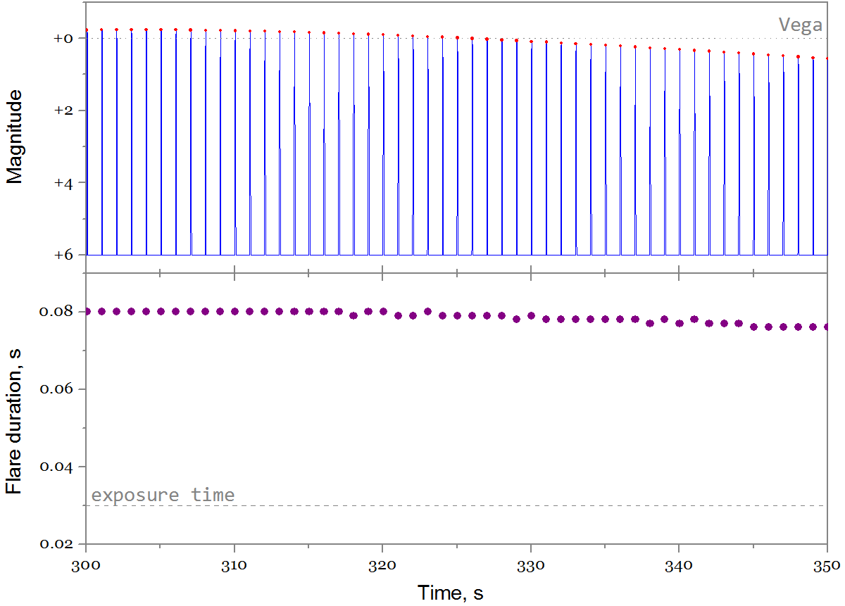
Flash at second! Captain Evidence suggests that this is how it should be for a satellite that is swirling at a speed of 1 rev / s. And the profile of a single flash looks like this:

The flash is really short and ends at +6 magnitude when it becomes dimmer than the background.
The main question that worries us is: when is the best time to observe flashes? To do this, you can run the script for different positions (= different local time) of the observer. What about the fact that we do not know the orientation of the satellite? You can perform calculations each time for several random orientations of the mirror and the axis of rotation, and then choose the brightest flash. The code will change like this:
line_theta_obs_0 = 134:2:236; % values of theta_obs_0 to be simulated number_of_iterations = 50; % number of different mirror orientations for one data point for counter_theta_obs_0 = 1:size(line_theta_obs_0,2) param.theta_obs_0 = line_theta_obs_0(counter_theta_obs_0); % calculate trajectory of the pass pass_path = fn_pass(param); and if the satellite flies on the horizon,
% loop over different random orientations of the mirror for counter_mirror = 1:number_of_iterations % create randomly oriented mirror and rotation axis param.d_rot = [rand, rand, rand]; param.n_mirror_0 = [rand, rand, rand]; % calculate the reflections and magnitudes of flares pass = fn_reflection(param, pass_path.reflection_intervals); pass = fn_flares(pass, param); end We launch it for 50 observer positions and 50 random orientations of the satellite, waiting for midnight (yes, it takes a lot of time to simulate), we get the result:

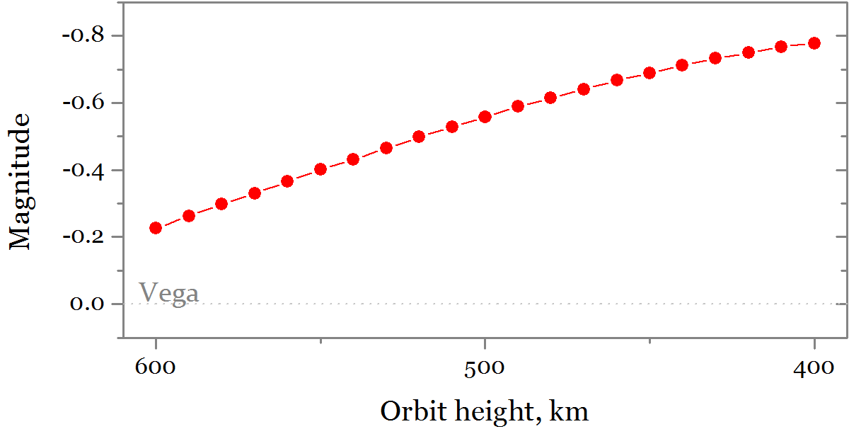
The brightest flashes fall at midnight — a fairly convenient time for observation. Evening flashes can also be bright. Unfortunately, shining brighter than Sirius and the planets will not work, but with a successful scenario, the satellite can be seen quite well. It can be seen that the brightness of the flashes decreases as the satellite moves away from the zenith (lower blue graph), which is associated with an increase in the distance to the satellite when it flies near the horizon. At the same time, the duration of the flashes (the average purple graph) remains almost unchanged.
What is the chance to see a bright flash? The only random element in the problem is the orientation of the satellite in orbit. In the cycle according to the orientations of the satellite, it was necessary to maintain the flash brightness for each iteration, and then build a histogram. ( Damn, I had to think about it right away! ) Add the necessary code and run the script for 100 satellite orientations. The next morning we get the result:

Here different flashes of different brightness are shown. The bar in the diagram is a specific local time; the probability of flashes of all kinds of brightnesses in it is 100%. It can be seen that the results are disappointing :
- flashes brighter than Vega (magnitude +0) can be seen for about an hour from 11:15 to 00:15; the probability of this is about 10%;
- flashes brighter than stars of the Big Dipper and Cassiopeia (brighter than +2) are visible a little longer than two hours (from 10 pm to half past midnight), the probability of seeing them is about 20%;
- with a probability of more than 50%, there will be no flares at all
Now the good news: three mirrors on the satellite . This does not mean that the probability will increase threefold (if only because then we would receive meaningless probabilities of 150%). But with a good arrangement of mirrors, an increase in the probability of two times is quite realistic, which is quite good. If you are very lucky, it will be possible to observe flashes from two mirrors in turn. Yes, it will not affect the brightness in any way - it will be possible to see anything brighter than Vega only at the “finest hour” around midnight.
Let's count something else. For example, how the flash brightness will vary depending on the satellite's spin speed .
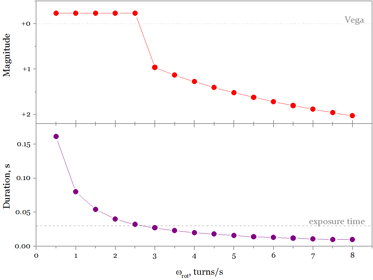
If the satellite rotates too fast, the flashes become too short (lower graph). Then the camera / eye rounds the exposure time to the lowest possible (1 frame or 0.03 s). At the same time, the flash brightness will drop. In our case, this happens at a spin of 3 rps.
And if the rotation speed is the opposite, too small? Also, nothing terrible up to ~ 0.01 rev / s. But below the flash will go too rarely - it may happen that the first flash will end long before the zenith, and the second will start strongly after. As far as I know, the Beacon will rotate at a speed of 0.1 - 1 rev / s, which is far from both the upper and lower limits - which means that with any twist we should see frequent bright flashes.
Well, now about the sad. The lighthouse century is very short - its huge mirrors will be slowed down by the residual atmosphere even at an altitude of 600 km. During the month, the satellite will drop to 400 km, where braking is even stronger, and within a few days after that it will enter the dense layers of the atmosphere. , , 0.6 :
- . " " — , , .
- ( , , - ) — 20 %.
- — "" .
Instead of an afterword
, – GUI, , , CUDA . , . .
, Quiensabe . – , , !
')
Source: https://habr.com/ru/post/307212/
All Articles