Finite automata in the SimInTech dynamic simulation environment. Part 2
In the first part, we showed how to create an algorithm based on “finite automata” in SimInTech and use it in conjunction with “classical” algorithms in the form of functionally block diagrams.
In the second part, we will show how to create nested and parallel-running state machines and exchange data between them.
Nested structures of finite automata. Implementing data exchange with state machines
SimInTech state machines are formed on the basis of standard submodels that support an unlimited nesting depth, we can place another or more state maps on the circuit inside the state machine and get a parallel-working set of state machines. Place on the circuit inside the model “Heater Controller” a new block “State Map of the State Machine” - this will be the automaton that determines the color and the blinking frequency of the heater indication. The internal structure of the block will consist of two states on and off.
')
Assemble the circuit as shown in fig. thirty
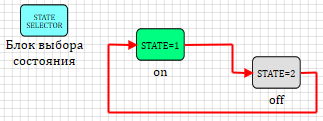
Figure 30. The internal structure of the automaton indicator.
For the active state, select the on state. Select the block and right-click on it. In the drop-down menu, select "Properties". A window for editing properties will appear, in which you need to select yes in the only “Default” property Yes (see Figure 31.)
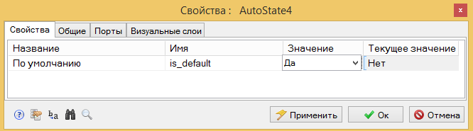
Figure 31. Setting the initial active state.
The internal structure of the logic of work in the enabled state is shown in Fig. 32.

Figure 32. The logic of operation in the On state
After turning on the state, the timer generates a signal of 0 (false) for a specified time. This signal by the “operator NOT” block is turned into 1 (true) and transmitted to the output of On. Until the time set in the “State Shutdown” block has expired, the On state will exit at the output of the On state block. - 0 (false) and will not change while the state is inactive. Thus, you can use this output as a status indication on.
Go up one level of the diagram above and put on the diagram the “Output port” block from the “Substructure” tab. This port will transmit an outgoing indicator signal. Assemble the circuit as shown in fig. 33.
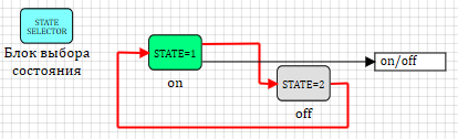
Figure 33 Diagram of the automatic display.
Enter the off state and type in a simple circuit, as shown in Fig. 34
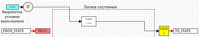
Figure 34. Scheme of operation in the off state
After the state is turned on, a timer is activated and after a time interval specified in the settings, the state is exited.
Go up two levels and connect the appeared output from the “Automatic Indicator” submodel with the “Led” output on the controller circuit, as shown in Figure 35.
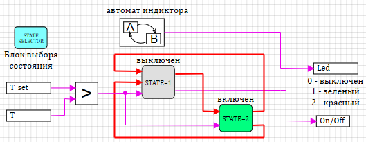
Figure 35. Heater controller circuit with an indicator automat.
If we now start the general scheme for the calculation, the indicator will switch between 0 and 1 with the interval specified in the state timer of the indicator automaton (see Fig. 32 and 34). By default, this time is 1 second and the “Display” graph in the general scheme (see Fig. 8) will be a meander with an interval of 1 second, as in Figure 36:

Figure 36. Schedule of the automatic display.
In order for the display automaton interval to depend on the state of the controller (1 second during heating and 5 seconds in the off state), it is necessary to transfer data to it from the parallel operating state machine. There are several ways to do this. Since state machines are implemented using conventional submodels, all data transfer methods can be used. In our example, we use one of them - the signals of the model.
Go inside the Heater Controller submodel. The diagram on the screen should look like in fig. 35. In the main menu of the main SimInTech window, select the Service item of the Signals submenu (see fig. 37)

Figure 37. Calling up project signals.
The window for setting the signal list will be called up. In this window, you can set project signals that all blocks used in the project have access to.
Create a new signal (the “add” button at the bottom of the window), set the name flash_time. Set the mode to “Omni-directional”; this will allow you to read and record this signal anywhere in the project (see Figure 38)

Figure 38. Adding a project signal.
This signal can be used for any purpose in the project. We will use it to set the indication interval in different states.
Switch to the automatic display and in the state timers for the on and off states, instead of the default value 1, set the signal name flash_time. (see fig. 39)

Figure 39. Setting the indication state exposure via the signal name.
Now, when we have the exposure time in the states of the indicator defined by the signal, you can change this value in different states of the controller, thereby changing the display interval.
Go to the Heater Controller status map and the status is off. Place the “Constant” block on the “Sources” tab and the “Programming language” block from the “Dynamic” tab on the diagram. Connect them as shown in fig. 40
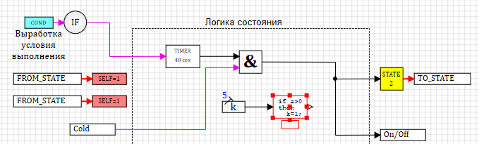
Figure 40. The status diagram is turned off with the setting of the indicator time.
Set the properties of the constant to 5 (5 seconds interval in the off state). In the general case, instead of a constant, there can be a scheme for calculating the interval of any complexity and any depth of nesting.
Enter the editor of the Programming language block by double-clicking and assign the value of the input (u) to the variable flash_time, as shown in fig. 41
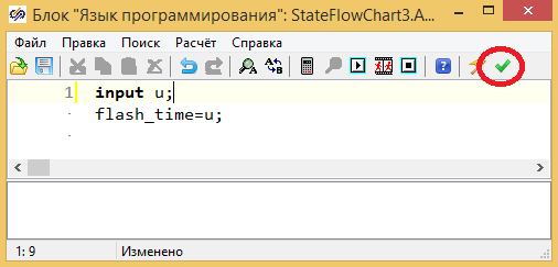
Figure 41. Setting the display interval in a programming language.
This text assigns the flash_time signal the value received from the input to the “Programming language” block. To accept the changes, click the Close and apply button at the top of the window. (see fig. 41).
You can not use the blocks and set the interval of the indicator directly in the text of the program. Let's do this for the enabled state.
Switch to the enabled state and place the “Programming language” block from the “Dynamic” tab on the diagram. Enter the block editor with double clicks and enter the text in the edit window, as shown in Figure 42.
Close the window by clicking on the "Close and apply" button at the top of the editing window.

Figure 42. Setting the indication interval for the state is included in the programming language .
If we start the calculation now, the “Display” graph will show us that the automatic display changes the switching interval depending on the state of the heater controller. In the off state, the interval is 5 seconds, in the on state - 1 second. (see fig. 43)

Figure 43. The schedule of the indicator with a different period.
As already described above, in SimInTech the logic of finite automata is implemented on the basis of standard submodels, therefore on the schemes with these blocks one can freely use the standard logic of model building.
For example, to change the indicator color calculation, you can modify the controller circuit so that, in addition to turning the indicator on and off (0.1), the indicator color value is also fed (0 - off, 1 - green is on, 2 - red is off). The scheme for calculating the color is shown in Figure 44.

Figure 44. Heater controller operation diagram with indicator color calculation
If you have collected all the diagrams, as described in this text, the graphs of the model will be similar to those shown below (see Fig. 45):

Figure 45. Results of simulation of a heater model with a controller built on the basis of finite automata.
On the graph showing the operation of the heater (upper graph of figure 45), it can be seen that in the off state with a period of 5 seconds, the output to the indicator changes the value 0 - 1 (green off), and in the on state this output with a period of 1 second changes the value 0 - 2 (red off). Please note that in the example above, the diagrams combine two approaches to creating control algorithms for the logic of "finite automata" and the standard functional block diagram of the algorithm and everything works fine together.
The dynamic simulation environment of technical systems SimInTech contains tools for creating a model of control systems based on state machines. This logic can be used together with the standard logic of functional block schemes (data flow), while the design and creation tools are fully compatible with each other.
The example shows the main methods of work when using the logic of "finite automata" in SimInTech. Download the version of SimInTech with state machine blocks here .
In the final part 3, we show how to generate the C code from the circuit in SimInTech. Part 3 is here ..
In the second part, we will show how to create nested and parallel-running state machines and exchange data between them.
Nested structures of finite automata. Implementing data exchange with state machines
SimInTech state machines are formed on the basis of standard submodels that support an unlimited nesting depth, we can place another or more state maps on the circuit inside the state machine and get a parallel-working set of state machines. Place on the circuit inside the model “Heater Controller” a new block “State Map of the State Machine” - this will be the automaton that determines the color and the blinking frequency of the heater indication. The internal structure of the block will consist of two states on and off.
')
Assemble the circuit as shown in fig. thirty
Figure 30. The internal structure of the automaton indicator.
For the active state, select the on state. Select the block and right-click on it. In the drop-down menu, select "Properties". A window for editing properties will appear, in which you need to select yes in the only “Default” property Yes (see Figure 31.)
Figure 31. Setting the initial active state.
The internal structure of the logic of work in the enabled state is shown in Fig. 32.
Figure 32. The logic of operation in the On state
After turning on the state, the timer generates a signal of 0 (false) for a specified time. This signal by the “operator NOT” block is turned into 1 (true) and transmitted to the output of On. Until the time set in the “State Shutdown” block has expired, the On state will exit at the output of the On state block. - 0 (false) and will not change while the state is inactive. Thus, you can use this output as a status indication on.
Go up one level of the diagram above and put on the diagram the “Output port” block from the “Substructure” tab. This port will transmit an outgoing indicator signal. Assemble the circuit as shown in fig. 33.
Figure 33 Diagram of the automatic display.
Enter the off state and type in a simple circuit, as shown in Fig. 34
Figure 34. Scheme of operation in the off state
After the state is turned on, a timer is activated and after a time interval specified in the settings, the state is exited.
Go up two levels and connect the appeared output from the “Automatic Indicator” submodel with the “Led” output on the controller circuit, as shown in Figure 35.
Figure 35. Heater controller circuit with an indicator automat.
If we now start the general scheme for the calculation, the indicator will switch between 0 and 1 with the interval specified in the state timer of the indicator automaton (see Fig. 32 and 34). By default, this time is 1 second and the “Display” graph in the general scheme (see Fig. 8) will be a meander with an interval of 1 second, as in Figure 36:
Figure 36. Schedule of the automatic display.
In order for the display automaton interval to depend on the state of the controller (1 second during heating and 5 seconds in the off state), it is necessary to transfer data to it from the parallel operating state machine. There are several ways to do this. Since state machines are implemented using conventional submodels, all data transfer methods can be used. In our example, we use one of them - the signals of the model.
Go inside the Heater Controller submodel. The diagram on the screen should look like in fig. 35. In the main menu of the main SimInTech window, select the Service item of the Signals submenu (see fig. 37)
Figure 37. Calling up project signals.
The window for setting the signal list will be called up. In this window, you can set project signals that all blocks used in the project have access to.
Create a new signal (the “add” button at the bottom of the window), set the name flash_time. Set the mode to “Omni-directional”; this will allow you to read and record this signal anywhere in the project (see Figure 38)
Figure 38. Adding a project signal.
This signal can be used for any purpose in the project. We will use it to set the indication interval in different states.
Switch to the automatic display and in the state timers for the on and off states, instead of the default value 1, set the signal name flash_time. (see fig. 39)
Figure 39. Setting the indication state exposure via the signal name.
Now, when we have the exposure time in the states of the indicator defined by the signal, you can change this value in different states of the controller, thereby changing the display interval.
Go to the Heater Controller status map and the status is off. Place the “Constant” block on the “Sources” tab and the “Programming language” block from the “Dynamic” tab on the diagram. Connect them as shown in fig. 40
Figure 40. The status diagram is turned off with the setting of the indicator time.
Set the properties of the constant to 5 (5 seconds interval in the off state). In the general case, instead of a constant, there can be a scheme for calculating the interval of any complexity and any depth of nesting.
Enter the editor of the Programming language block by double-clicking and assign the value of the input (u) to the variable flash_time, as shown in fig. 41
Figure 41. Setting the display interval in a programming language.
This text assigns the flash_time signal the value received from the input to the “Programming language” block. To accept the changes, click the Close and apply button at the top of the window. (see fig. 41).
You can not use the blocks and set the interval of the indicator directly in the text of the program. Let's do this for the enabled state.
Switch to the enabled state and place the “Programming language” block from the “Dynamic” tab on the diagram. Enter the block editor with double clicks and enter the text in the edit window, as shown in Figure 42.
Close the window by clicking on the "Close and apply" button at the top of the editing window.
Figure 42. Setting the indication interval for the state is included in the programming language .
If we start the calculation now, the “Display” graph will show us that the automatic display changes the switching interval depending on the state of the heater controller. In the off state, the interval is 5 seconds, in the on state - 1 second. (see fig. 43)
Figure 43. The schedule of the indicator with a different period.
As already described above, in SimInTech the logic of finite automata is implemented on the basis of standard submodels, therefore on the schemes with these blocks one can freely use the standard logic of model building.
For example, to change the indicator color calculation, you can modify the controller circuit so that, in addition to turning the indicator on and off (0.1), the indicator color value is also fed (0 - off, 1 - green is on, 2 - red is off). The scheme for calculating the color is shown in Figure 44.
Figure 44. Heater controller operation diagram with indicator color calculation
If you have collected all the diagrams, as described in this text, the graphs of the model will be similar to those shown below (see Fig. 45):
Figure 45. Results of simulation of a heater model with a controller built on the basis of finite automata.
On the graph showing the operation of the heater (upper graph of figure 45), it can be seen that in the off state with a period of 5 seconds, the output to the indicator changes the value 0 - 1 (green off), and in the on state this output with a period of 1 second changes the value 0 - 2 (red off). Please note that in the example above, the diagrams combine two approaches to creating control algorithms for the logic of "finite automata" and the standard functional block diagram of the algorithm and everything works fine together.
findings
The dynamic simulation environment of technical systems SimInTech contains tools for creating a model of control systems based on state machines. This logic can be used together with the standard logic of functional block schemes (data flow), while the design and creation tools are fully compatible with each other.
The example shows the main methods of work when using the logic of "finite automata" in SimInTech. Download the version of SimInTech with state machine blocks here .
In the final part 3, we show how to generate the C code from the circuit in SimInTech. Part 3 is here ..
Source: https://habr.com/ru/post/307162/
All Articles