The history of one diploma or how to make a sharabota
The history of this project begins in 2014, when I was studying for the 4th year in the leading technical university of Russia at the Department of Robotic Systems. At that time I started to think about the subject of the diploma and was looking for a project that would be interesting to me, and at the same time there was some novelty in it. Then one day, after seeing the video of the scarabber Rezero , my friends and I wanted to try to repeat the success. Who cares what came out of it - I ask for cat.
Introduction
In the beginning I would like to talk about the merits of the sharabota. Thanks to a single point of contact with the surface, the sharabot is equally easy to move in all directions, being extremely mobile and maneuverable, compared to conventional wheeled robots. The maneuverability of the sharabot is limited only by its dynamics, in contrast to the mechanical limitations imposed by the wheels (for example, the impossibility of moving sideways).
The next important advantage is that a robot can be high, and the higher it is, the more stable it will be. Why steadier? This is evident from the equation of the dynamics of the inverse pendulum. Acceleration of the deviation from the vertical equilibrium position is inversely proportional to the distance to the center of mass, i.e. the higher reverse pendulum will fall more slowly. This reduces the response speed requirements of the control system, but perhaps increases the moment that the drive should develop.
Another advantage is that it can travel on inclined and moving surfaces, for example, the deck of a ship or the floor of an aircraft during takeoff. And you see, it moves much more beautifully than ordinary wheeled robots.
One of the main drawbacks of the sharabota is the possibility of losing the vertical position of balance. But personally, I think this is a completely solvable engineering problem. The engineers of the robots Aido and Mobi decided it as follows: when a certain angle of deflection is exceeded, the “legs” are advanced so that the robot does not lose stability.
My story consists of the following parts:
- Mathematical model
- Development of control algorithms
- Construction
- Hardware and software
- Results
1 Mathematical model
The derivation of the equations of motion is necessary for the further synthesis of control and the simulation of motion. In this section there will be some math and mechanics.
At the moment, all existing mathematical models of the sharabota are made taking into account some simplifications using the Lagrange equations of the 2nd kind. And since the scarabot is a nonholonomic mechanical system, it is incorrect to apply the Lagrange equations of the 2nd kind to such a system. In the CMU robot, the scarab model is considered as three independent flat models, thereby not taking into account the mutual influence of these models. Rezero developed a three-dimensional mathematical model, which does not take into account the gyroscopic effects that occur during the rotation of the omnic wheel.
I set a goal to create the most complete mathematical model of the robot with the minimum number of assumptions. My scientific adviser S.L. helped me to achieve this goal. Krutikov, for which I express my deep gratitude to him.
1.1 Kinematics
For the kinematic description of the system, I introduced the moving coordinate systems shown in the figure.
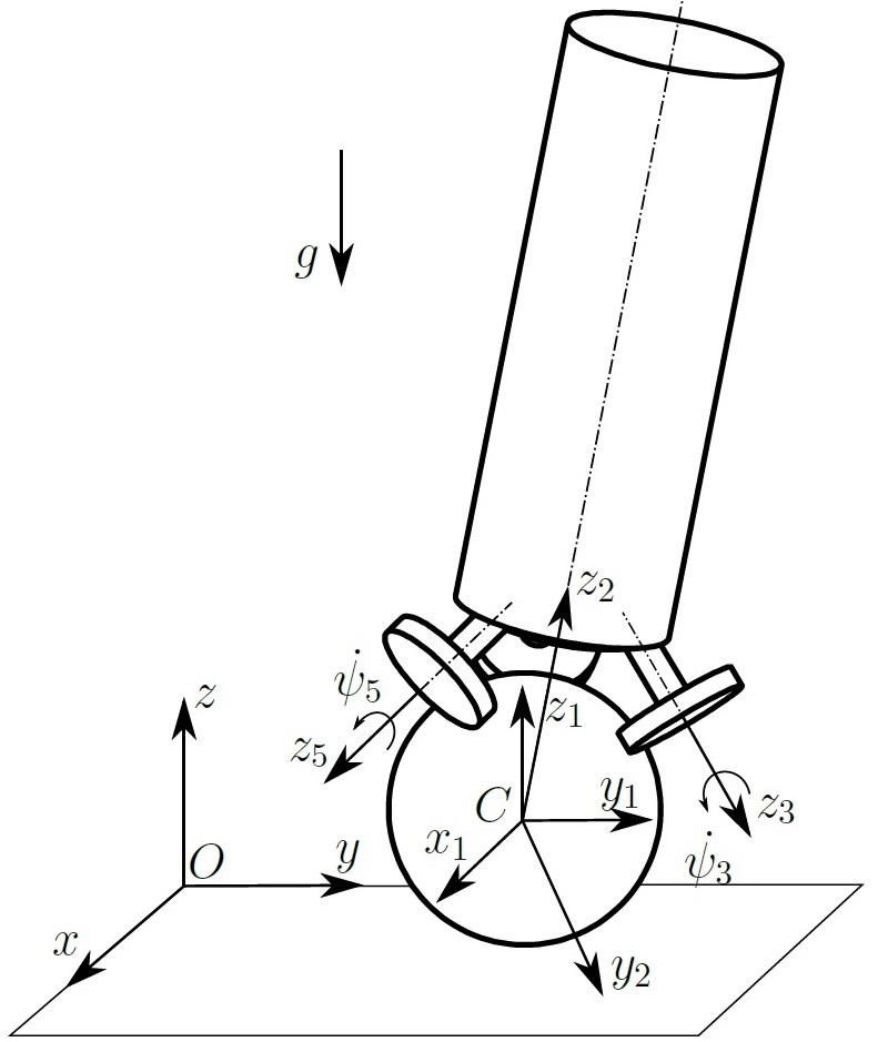
Inertial coordinate system is designated as . Coordinate system
located in the center of the ball. To go from the inertial frame of reference to the center of the ball, the following homogeneous matrix is used:
Where and
the displacement of the center of the ball along the axis
and
respectively.
To describe the rotation of the ball, it is convenient to use the gimbal angles or the Tait – Bryan angles. So the coordinate system associated with a ball is obtained by turning
on the corners
,
and
around the axes
and
respectively. This sequence of turns can be represented as a product of turning matrices:
Similarly, one can describe the rotation of the body of a scarabot in space. Coordinate system The 2nd link associated with the body is obtained by turning
on the corners
,
and
around the axes
and
respectively. This sequence of turns can also be represented as a product of turning matrices:
The 3rd, 4th and 5th coordinate systems are associated with omniwheels. To move from the body's coordinate system to the omni-wheel coordinate system, you need to perform a series of elementary transformations (two rotations, transference, then rotation again), I will not describe them here.
The sequence of transitions is represented as the following kinematic graph:

To describe the position of the system, the following vector of generalized coordinates is used:
Where - coordinates of the center of the ball,
- cardan angles describing the rotation of the ball and the body, respectively,
- angles of rotation of omnic wheel around the axis of the engine.
1.2 Dynamics
On the basis of the nonholonomicity of the system, it was decided to use the Appel equations to compose the differential equations of motion of the sharabota.
6 nonholonomic constraints are imposed on the system: three omniwheel rolling bonds along the ball, two bonds for the ball center speed and one bond of the ball spinning. Thus, the number of generalized coordinates is m = 11, the number of constraints is s = 6, and the number of degrees of freedom is n = 5. We will use the following pseudo-velocity vector:
To compile the equations of motion, it is necessary to calculate the acceleration energy for each link:
Where - the number of links
- transition matrix from inertial coordinate system to coordinate system
link,
- inertia matrix
link, and
- trace matrix . In general
is a function of
. Using the equations of the coupling, the acceleration energy is reduced to a function depending only on
.
The matrix of inertia of the ball has a diagonal view, since coordinate system axes are the main central axes of inertia:
Since plane and
are the planes of symmetry of the body, the centrifugal moments of inertia
and
are zero. The body inertia matrix will look like this:
Where - distance from the center of the ball to the center of mass of the body along the axis
.
The omni-wheel inertia matrix has a diagonal view, since The axes of the omni-wheel coordinate system form planes of symmetry:
In the moment of inertia it is also necessary to take into account the moment of inertia of the rotor of the engine:
Where - The gear ratio of the gearbox.
Appel's differential equation of motion in pseudo-coordinates:
Where - the generalized force from the moments of the drives,
- generalized force from gravity.
Write the Appel equations in matrix form and decide on :
The equations of motion can be written in matrix form.
Where
All calculations were performed symbolically using Maple. Then the resulting equations were transferred from Maple to Matlab for modeling.
')
2 Development of control algorithms
A little more control theory and the match ends here. In control theory, methods for analyzing linear systems are well developed. For completely observable systems, optimal control with a quadratic functional (linear quadratic regulator, LQR) is most often used, which guarantees the stabilization of the system if the system is completely controllable. Sharobot is a completely observable system, since state vector can be fully measured. Having calculated the rank of the controllability matrix, I was also convinced of the controllability of the system.
To obtain a linear-quadratic controller at the beginning, it is necessary to linearize the system in the vicinity of the vertical position of unstable equilibrium
Vector - state vector or phase vector,
- vector of measurement and
- control (drive moments).
The LQR controller has the following optimality criterion:
Where and
- positive definite matrix. The task of minimizing this functional is reduced to solving a matrix algebraic Riccati equation:
For a linear-quadratic controller, the control is written as where
,
- solution of the Riccati equation. As a result, we have a matrix of feedback coefficients:
When multiplying this matrix by the state vector we get three points that need to be applied to the engines to stabilize the system. LQR is a PD regulator if the state vector consists of coordinates and their derivatives. As you understand, it is almost impossible to use the usual PID controller and manually select coefficients in such a system.
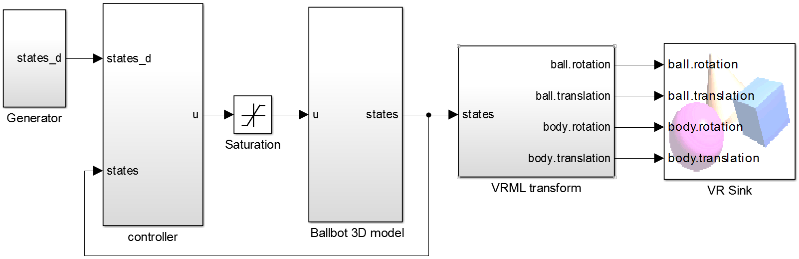
I will give a small explanation of each unit. In the block “Ballbot 3D model” the Appel equations are realized. At the entrance is administered (three moments), the output is the state vector
(see item 2).
The VRML transform block transforms the state vector into coordinates for visualization. “VR Sink” contains a model in vrml format and it is this block that draws the graphics.
The state vector is fed to the input of the “controller” block and the desired state vector
, with which you can set the trajectory of movement and speed. The block produces elementary deceleration of the matrices for three moments.
.
Since the moment that the drive develops is limited, I added a saturation link.
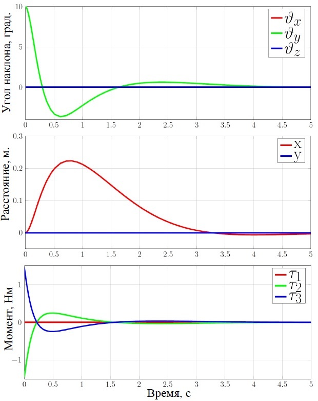
For the three-dimensional visualization was made a simple model of a scaffold in SolidWorks. It was then exported in vrml format and added to the VR Sink block.

Simulation results with an initial deviation of 10 degrees
3 Construction
The design of the robot is developed in the Siemens NX CAD system. On the basis of the constructed model, the mass and inertial characteristics of the robot links were determined.
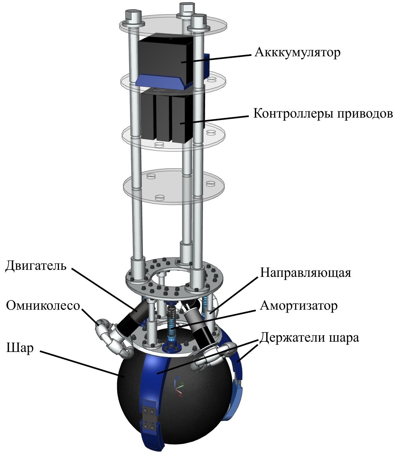
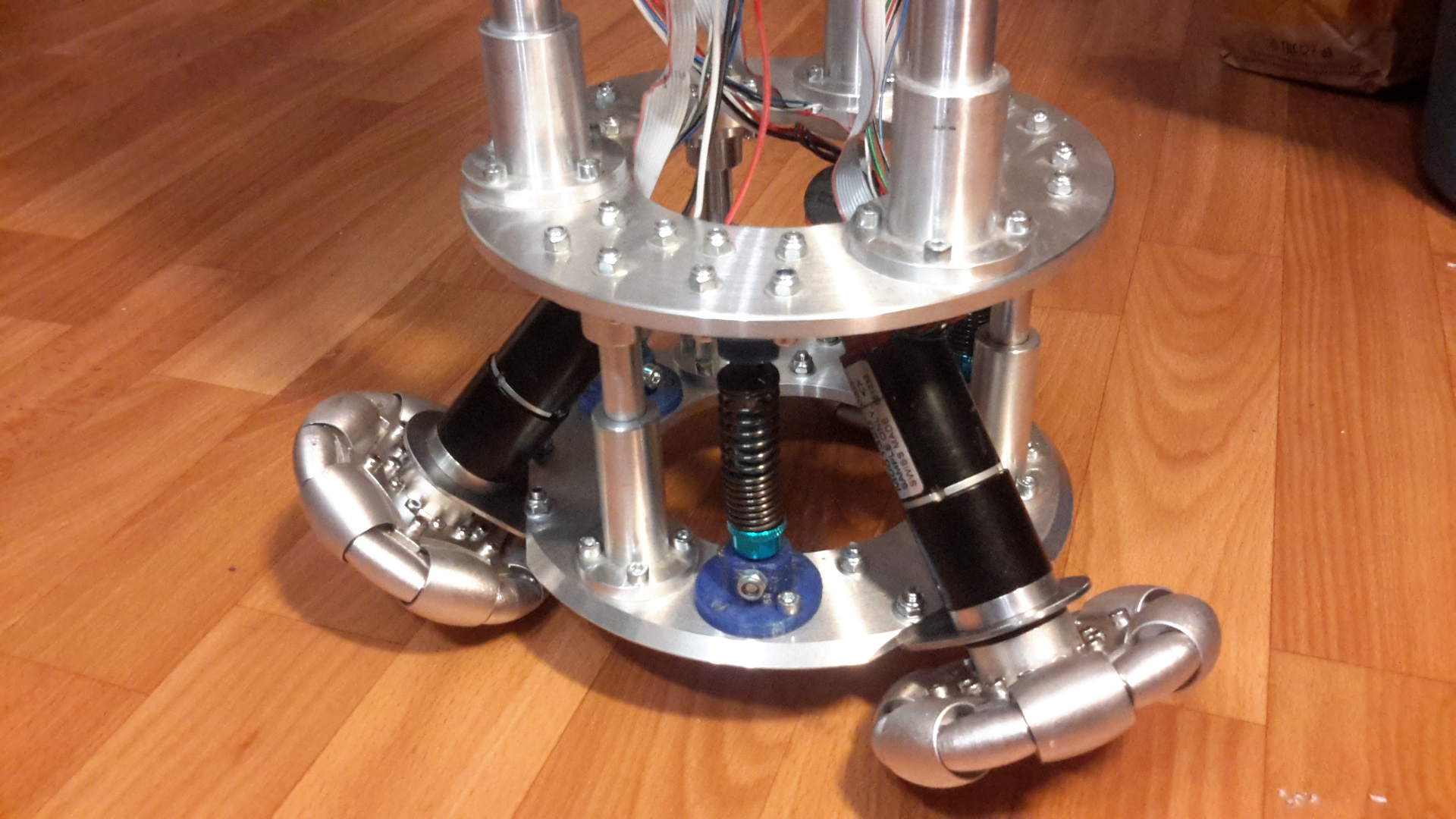
The design consists of two aluminum bases. Three engines are mounted on the lower base, which drive the omnic wheel. The upper base is attached to the bottom with shock absorbers and guides. The task of shock absorbers was to reduce the vibrations of the upper part of the body, where all the electronics are located, although this did not help in practice.
The shelves are made of plexiglass to facilitate construction. They contain all the onboard electronics: battery, drive controllers, microcontroller, inertial, etc.
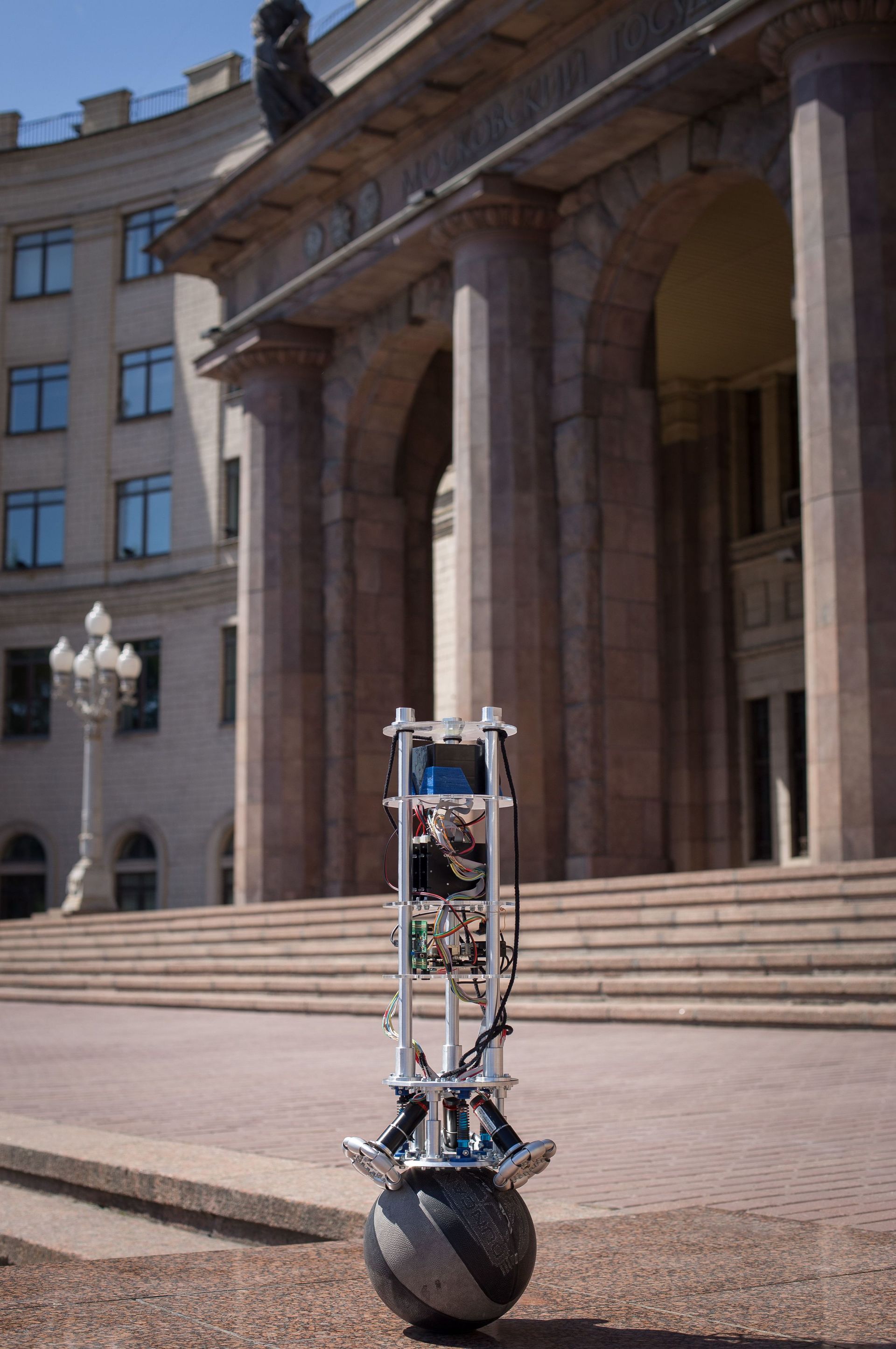
The ball is a basketball with a diameter of 240 mm. The ball holders press it against omnic wheels, thereby increasing friction. Unfortunately, they could not be made, as there is no 3D printer in our department, and printing on order is expensive, because they are not small and the fill factor is needed big for durability.
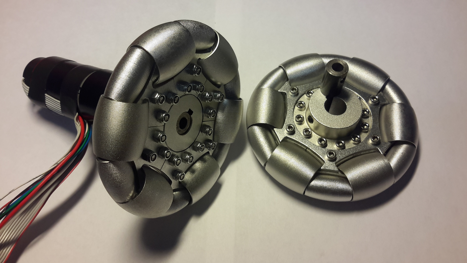
Omnicoles were purchased on Aliexpress for $ 120 apiece. The most expensive part of the robot, after the drives, of course.
All metal parts are made of duralumin to order at one Moscow factory. At the same factory we made shelves of plexiglass. The order came in the amount of 30 000r, approximately.
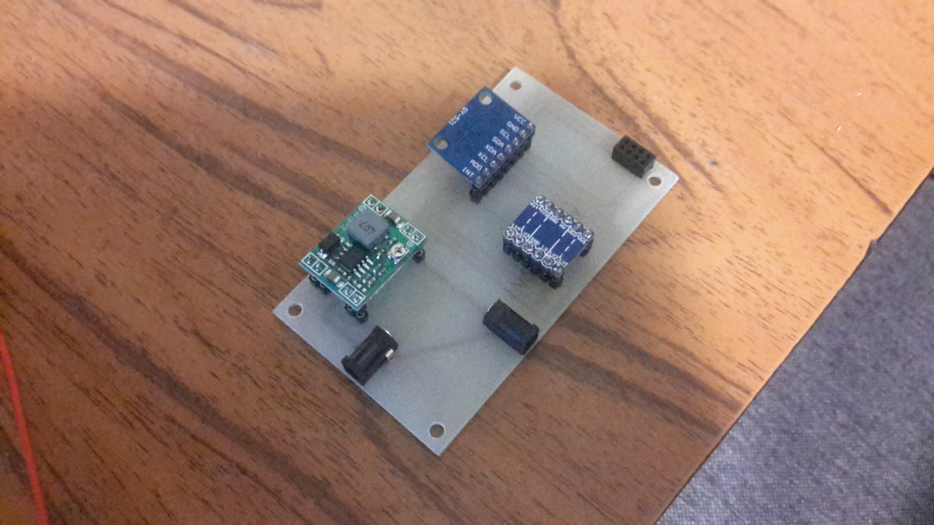
A friend helped me dissolve the board on which the DC-DC converter, IMU and logical level converter for I2C are located. ODROID stuck on top

This is the very first design with Dynamixel MX64 drives. Drive boxes are printed.
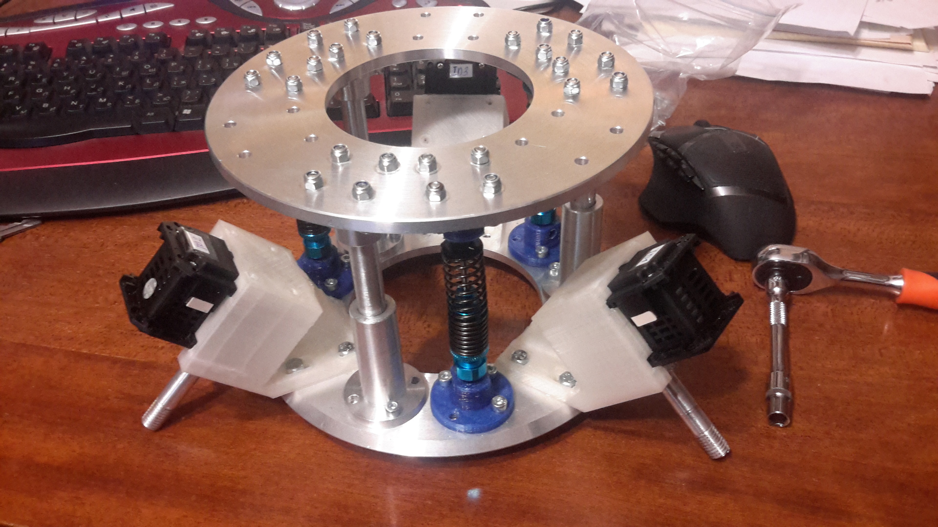
HSP shock absorbers for radio-controlled models with a scale of 1:10.

As such, I got a set of drives and controllers.
In order to put the omniwire on the motor shaft, the sleeve had to be turned out.
This is the final result.
4 Hardware and software
Almost all hardware components of a scarab are represented in a functional diagram. I will say a few words about each element, moving "from the bottom up."

4.1 Drives and Drive Controllers
It was harder for everyone to find drives and drive controllers. At the output of the LQR regulator we have a moment, therefore we need to have a controller with the ability to control current (i.e. by moment). Apparently, this task is very rare in everyday life, and we found only one affordable solution, Dynamixel. We bought and tried a Dynamixel MX64 drive, which has a current control mode. Unfortunately, their speed was not enough to stabilize the robot.
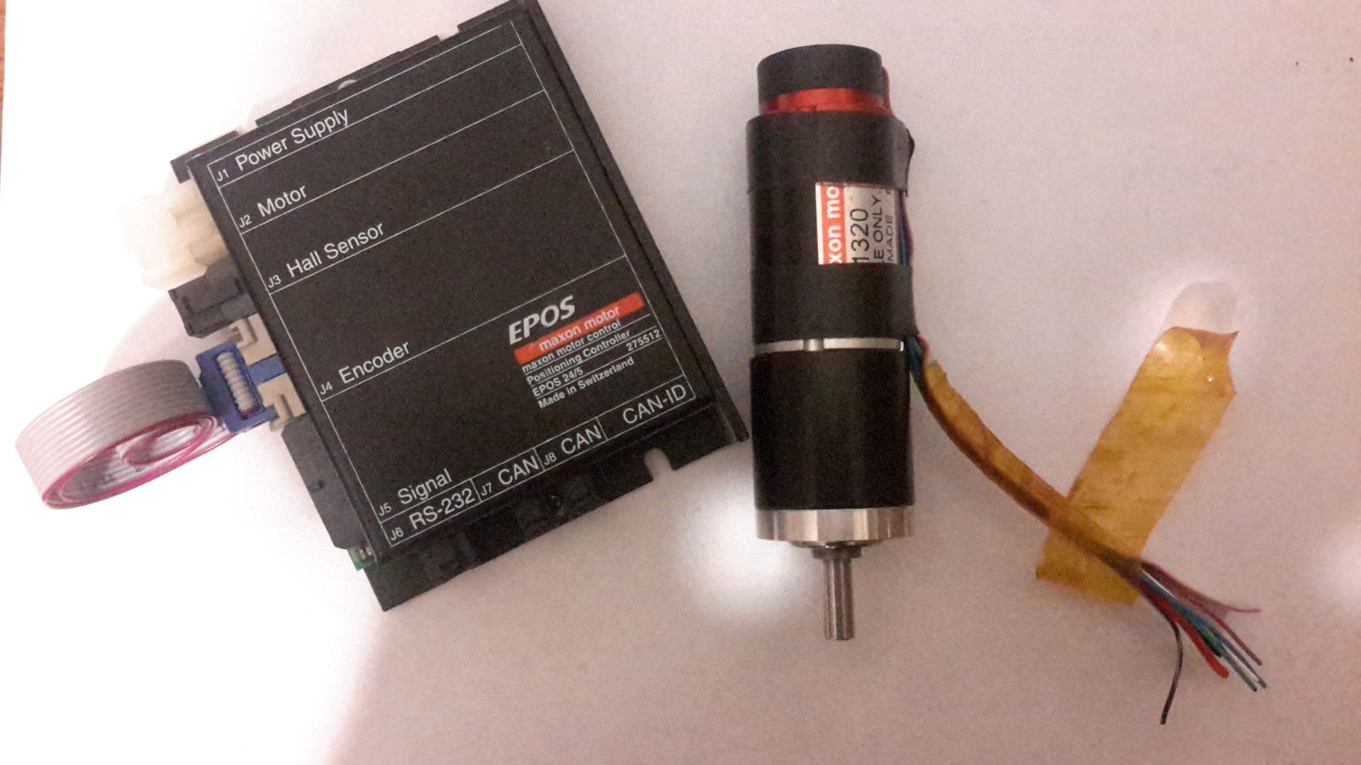
I had already lost hope of creating a real sharabota, but fortunately Yaroslav from the RCC Robotics helped us and provided for some time three Maxon drives with controllers, for which we are very grateful. As a result, we had a Maxon EC-max 30 40W brushless DC motor with the following characteristics:
- Rated voltage 24V
- Nominal rotational speed of 7220 rev / s
- Nominal torque of 33.8 mNm
- Holding moment 160 mNm
Maxon GP 32 planetary gearbox with a ratio of n = 14 and Maxon EPOS 24/5 drive controller, which has a current control mode.
As you can see, the drive is not very powerful and the gear ratio is small, so the moment at the output is hardly enough to stabilize the scatter beam. The Rezero, for example, uses 200W motors and a gearbox with a gear ratio of 51.
4.2 Microcontroller, inertial module, transceiver
The STM32F4-Discovery was used as a microcontroller, which has the interfaces we need: CAN, UART and I2C. It receives data from the gyroscope and accelerometer via I2C and encoders via CAN bus. Based on the received data, it calculates the control and sends the task to the drive controllers via CAN bus. In order not to implement the protocol for communicating with EPOS controllers myself, I used the library of libepos . In order to connect the STM to the CAN network, a CAN transceiver (transceiver) for $ 4 is needed.
As an inertial module, we used a $ 3 GY-521 board based on the MPU6050 chip, which includes a 3-axis gyroscope and a 3-axis accelerometer. For processing the readings of these sensors, I used the filter Madjvika , which recently so loved kopterovody.
To simplify development under STM, I used the STM32Cube HAL (hardware abstraction layer).
The frequency at which the control works is about 300 Hz, i.e. 300 times a second, we read all the sensors, calculate the control and send the task to the drive. All this happens in an infinite loop, which can be represented as the following pseudocode:
int main() { initialize_imu();/* IMU I2C */ initialize_motors(); /* CAN */ while (1) { read_imu(); /* IMU */ get_omniwheels_speed(); /* CAN */ /* UART odroid */ if (uart_rx_flag) { uart_rx_flag = 0; struct joystick_data* joystick = (struct joystick_data*)UARTdev_Get_RX_buf(); process_joystick_input(joystick); } calculate_control(); /* */ set_torque(); /* CAN */ } } 4.3 Single board computer, battery, DC-DC converter, joystick
The onboard single board computer ODROID U3 receives data from the joystick via a Bluetooth adapter and transmits it to the microcontroller via the UART. It has a lubuntu operating system with Linux 3.8.13.26-rt31 kernel with real-time support.

Lead-acid battery Delta 12045 with a capacity of C = 4.5 Ah. It lasts about an hour of work.
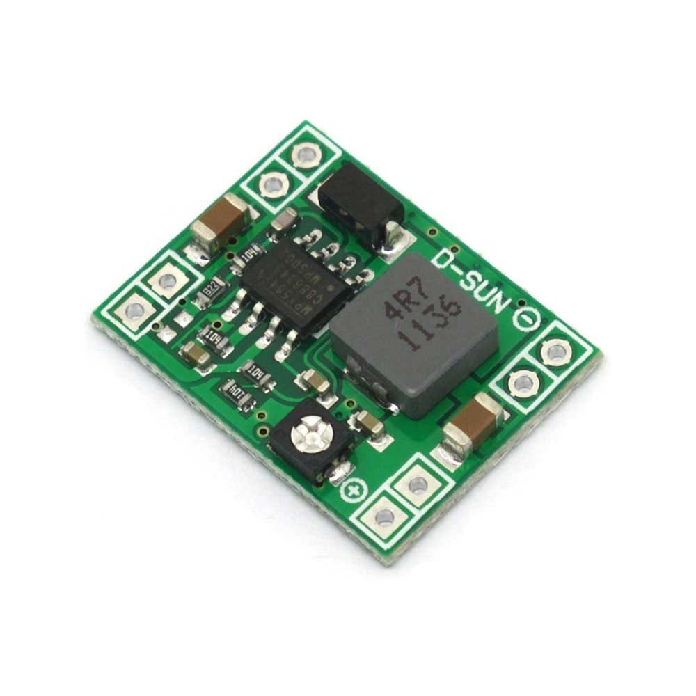
The voltage of the single-board computer Odroid-U3 5V, the maximum current consumption of 2A. Since power supply 12V, a buck $ 2 LM2596S DC-DC converter is needed.
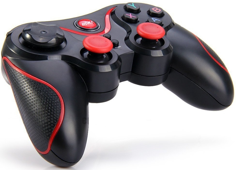
To control the scarab, Bluetooth uses a Terios joystick. The joystick transmits commands via Bluetooth to the ODROID, which contains the Asus USB-BT400 adapter. To read the commands of the joystick, I used the following library . The incoming command is parsed, packed and sent over the UART to the STM32, where an interrupt occurs at the reception of each byte.
You can also connect to ODROID via SSH. When started, the odroyd creates an ad-hoc network via a wifi adapter.
results
Total we managed to collect a working sharabota. It took exactly 2 years to implement this project. Let's just say that we didn’t manage to get close to the results of Rezero, as there were no such human, industrial and financial resources as students from Switzerland. I think if there were more powerful engines and a more advanced inertial module, the results would be much better.
The source code I do not open for some reason. If you want to know the details of implementation - write to us, we will be happy to share with you the developments. The engines had to be returned and at the moment the piece of iron stands without them. Perhaps the project will be further developed by students, if there are suitable engines and there are those who wish. For example, it would be interesting to develop nonlinear control algorithms and improve the IMU filtering algorithm.
I spoke rather superficially about the development process, so I will be glad to answer your questions.
Source: https://habr.com/ru/post/306456/
All Articles