RS-422 pairing adapters supporting speeds up to 1Mbaud for PCI system bus
annotation
The article describes a modification of commercially available multi-port I / O expansion adapters built on NetMOS / MosChip MSC98XX-CV and SystemBase SB16C1052PCI chips for implementing RS-422 serial physical interface with data rates up to 1 Mbaud.
Text
Since the time of the IBM PC computers, serial ports of personal computers, workstations and servers operating under the UART protocol, in most cases use the physical signal interface RS-232. Previously, serial ports, or COM ports in the terminology of system software, were used mainly to connect mouse manipulators and modems for dial-up telephone lines and other low-speed communication channels. In modern computing, these peripherals are connected via USB. However, RS-232 serial ports continue to be used for interfacing with various technological equipment, such as a barcode scanner, as well as for various debugging and diagnostic needs for terminal operation with firmware for devices such as third-party network switches. level controllers, uninterruptible power supplies, etc.
The RS-232 serial signaling interface uses bipolar signals with an amplitude of 5 to 15 volts, with a negative voltage corresponding to a logical one, and a positive voltage to a logical zero. Signals with such amplitude cannot transmit data at high speeds, whereby the maximum speed for a standard serial port is limited to 115.2 kbaud. When synchronizing a UART class 16550 from a signal with a frequency of 1.8432 MHz, the speed of 115.2 kbaud corresponds to setting the register of the DLL to zero, and the register of DLM to 00000001.
In addition to the RS-232 signaling interface, serial ports can use RS-422 and RS-485 standards, which allow data to be transmitted in the form of electrical signals over a cable with a speed of up to 10 Mbaud at distances of 10–20 m and providing a communication range of up to 1500 m at low speeds. The use of RS-422 and RS-485 signaling standards with UART interfaces is common in industrial and special equipment designed for harsh operating conditions.
')
For the interfacing of personal computers and industrial computers with RS-422 serial interface, specialized input / output adapters are available that implement up to 16 UART channels. As an example, consider the Advantech PCL-743 adapter for the ISA system bus, shown in fig. 1. This adapter contains two UART 16C550 controllers that control the Xilinx XC9572 FPGA and RS-422 / RS485 transmitters and transmitters. By setting the switches, the address ranges that the adapter uses for the 16C550 controllers are set. If the switches are correctly set, it is possible to configure the adapter to operate as standard COM ports, determined by the BIOS and the operating system. To do this, set the base addresses of 16C550 controllers to the values from the list: 02E8h, 02F8h, 03E8h, 03F8h, so that there is no coincidence with the address ranges of the motherboard's COM ports.
In addition, the adapter allows you to configure the physical interface operation mode for each of the two ports separately, either according to the RS-422 standard or according to the RS-485 standard.
To achieve high speeds, a PCL-743 adapter has a crystal oscillator that forms a frequency of 14.7456 MHz, which is 8 times higher than the standard frequency of 1.8432 MHz. The position of the extreme right switch sets the synchronization frequency of the controllers 16C550: either standard or increased 8 times. High frequency operation allows operation at speeds of up to 921.6 kbaud, for which the speed setting of 115.2 kbaud is selected in the software.
Jumpers on the left side of the adapter card allow you to manually configure the interrupt lines for each UART channel.
The considered adapter is a rather expensive and outdated solution due to the lack of an ISA bus in modern computing systems.
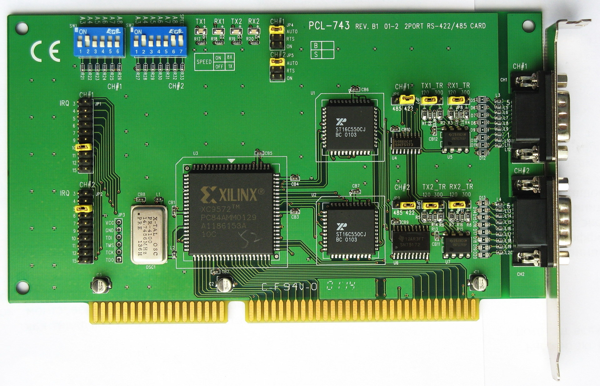
Fig. 1. Interface adapter PCL-743 from Advantech
It is proposed to consider the implementation of serial port adapters operating under the RS-422 standard at speeds up to 1 Mbaud by modifying low-cost controllers of traditional peripheral interfaces for the system PCI bus, widely represented on the market.
The basis for the adapters described in the article are the Espada multiport controllers based on MCS9820, MCS9835, MCS9845 from MosChip. The MCS9805, MCS9815, MCS9820, MCS9835, MCS9845 chipset family was developed by NetMOS 10-12 years ago with a high degree of unification of pinout and internal logical organization. This unification made it possible to develop a number of peripheral interface controllers using a common PCB design.
The following Espada controllers are built on a single printed circuit board, and differ exclusively in the configuration of the installed connectors and electronic components:
• FG-PIO9820-1S-01-CT01 - one RS232 port, MCS9820 chip;
• FG-PIO9835-2S-01-CT01 - two RS232 ports, MCS9835 chip;
• FG-PIO9835-2S1P-01-CT01 - one LPT port, two RS232 ports, MCS9835 microcircuit;
• FG-PIO9805-1P-01-CT01– one LPT port, MCS9805 chip;
• FG-PIO9815-2P-01-CT01– two LPT ports, MCS9815 microcircuit.
Also, the unified PCB is used by Espada controllers, based on the MCS9845 chip, which has an external asynchronous bus, through which additional UART controllers of types 16C550, 16C552, 16C554 are connected:
• FG-PIO9845-4S-01-CT01 - four RS232 ports, chips MCS9845 + 2pcs. 16550;
• FG-PIO9845-6S-01-CT01 - six RS232 ports, MCS9845 + 16C554 chips.
The appearance of the maximum configuration controller with six RS232 serial ports is shown in fig. 2
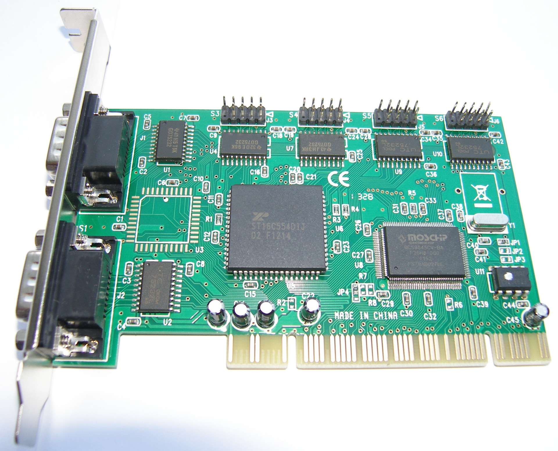
Fig. 2. Espada RS232 interface adapter
In the original configuration, all listed Espada adapters have level converters for working with RS-232 interface and are configured to work with a maximum speed of 115.2 kbaud. However, in the early versions of the documentation for the MCS98xx-CV chips, the maximum speed of operation of the serial port controllers is 1Mbaud [1, 2]. In later documentation, the maximum speed was reduced to 115.2 kbaud [3, 4], which was most likely made from commercial considerations due to the entry into the market of more advanced interface chips MosChip MCS9865-IV, supporting the function of the PCI bus initiator (master) .
The MCS9820, MCS9835, MCS9845 chips have up to two integrated UART class 16C550 controllers using separately configured through the configuration registers PCI I / O address ranges with a capacity of eight bytes. Adapters that implement more than two serial ports use a bunch of MCS9845 and 16C550 (16C552, 16C554) microcircuits connected by an asynchronous 8-bit local bus to which read and write PCI bus transactions are transmitted to the I / O addresses belonging to the ranges of additional UART controllers in the composition 16C550 microcircuits (16C552, 16C554). The I / O address ranges of the additional UART controllers are also configured through the base address registers - BAR in the PCI configuration space. Registers of the PCI configuration space are implemented according to the standard [5] in MCS98xx chips and are available for reading and / or writing by means of the system controller included in the chipset.
For synchronization of UART controllers, the MCS9820, MCS9835, MCS9845 microcircuits include two carrier frequency feed inputs:
• the ACLK signal (pin 59) sets the carrier frequency for the UART-A,
• BCLK signal (pin 57) sets the carrier frequency for the UART-B.
The carrier frequency of the UART Class 16C550 controller should be 16 times higher than the baud rate. Thus, for a speed of 115.2 kbaud, a carrier of 1.8432 MHz is required, and for a speed of 1 Mbaud, the carrier frequency must be equal to 16 MHz.
According to MosChip's proprietary documentation [1-4], the inputs of ACLK and BCLK are proposed to be sent from a clock generator included in MCS98xx microcircuits. However, these inputs can be supplied from an external clock source with CMOS or TTL levels.
The built-in clock generator requires an external quartz crystal connected between the XTAL1 input (pin 62) and the XTAL2 output (pin 61) and generates three output frequencies:
• 3XCLK signal (pin 55) with the frequency obtained by dividing the frequency of the quartz resonator by 3,
• 6XCLK signal (pin 56) with the frequency obtained by dividing the frequency of the quartz resonator by 6,
• 12XCLK signal (pin 58) with the frequency obtained by dividing the frequency of the quartz resonator by 12.
In the original configuration of RS-232 interface adapters based on MCS9820, MCS9835, MCS9845 microcircuits, a quartz resonator with a frequency of 22.1184 MHz is used, and the ACLK and BCLK inputs are output from the 12XCLK output, the frequency of which is, respectively, 1.8432 MHz.
Most adapters based on MCS9820, MCS9835, MCS9845 microcircuits have resistor jumpers of size 0603, which allow the installation of ACLK and BCLK inputs from the 3XCLK, 6XCLK and 12XCLK outputs by mounting to different positions on the board. Thus, replacing the crystal oscillator with an analogue with a frequency of 48 MHz, and soldering the jumpers to the position corresponding to the switching of the ACLK and BCLK inputs to the 3XCLK output, we obtain the carrier frequency of the integrated UART controllers equal to 16 MHz. After such a revision, the system speed of the serial port of 115.2 kbaud (in the software settings) will correspond to the real speed of 1 Mbaud.
The result of such a revision made on the Espada FG-PIO9820 or FG-PIO9835 adapters is shown in fig. 3

Fig. 3. Refinement of the Espada adapter to support 1 Mbaud rate
The overwhelming majority of serial port interface adapters on the market implement RS-232 interfaces, which are derived from DB-9M connectors. The RS-232 interface was initially focused on connecting telecommunications equipment, as a result of which it has a number of special signals, also implemented in UART controllers of the 16450 and 16550 classes.
The classical connection scheme of devices via RS-232 interface includes DTE (Data Terminal Equipment) terminal equipment and DCE (Data Communication Equipment) data communication equipment, connected by a direct cable. The term “straight cable” refers to a cable with connectors of the socket and plug type, in which the contacts are connected under the same number (a cat-1 plug is connected to a contact-1 socket, a cat-2 plug is connected to a contact-2 sockets, etc. )
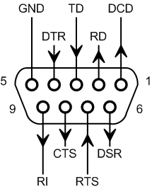
For terminal equipment, DTE traditionally uses a DB-9M type connector (plug), the wiring of which is shown in fig. 4, a. The role of the terminal equipment is a personal computer, a workstation, a server, a LAN switch, a controller, or other equipment containing a microprocessor acting as a generator of information packages.
For DCE data transmission equipment, a DB-9F type connector (socket) is traditionally used, the wiring of which is shown in fig. 4, b. Data transmission equipment is traditionally represented by modems for various communication channels, which form special control signals nRI - a call signal from PBX and nDCD - a sign of carrier frequency detection in a communication channel. Also in the role of DCE can be any other device that performs the functions of a receiver of information packages, or a passive source of packages, such as execution units and sensors.

but
b
Fig. 4. Distribution of RS-232 connectors:
a - DB-9M plugs for DTE, b - DB-9F sockets for DCE
The diagram of direct connection of DTE and DCE devices via RS-232 interface is shown in fig. 5. The direct interface cable has a DB-9F socket for connecting to a DTE (computer) and a DB-9M plug for connecting to DCE telecommunications equipment (a modem). The cable has 9 insulated connections in a common screen, connected to metal cases of the plug and sockets at the ends.
In connections that do not use special signals from the carrier detector nDCD and call nRI, the division of devices into DTE and DCE types is rather conditional and is mainly determined by the type of connector: the plug at the DTE and the socket at the DCE.

Fig. 5. Diagram of direct connection via RS-232 interface
In modern equipment, based on unification considerations, they prefer to use DTE type connectors. To connect two DTE devices use a zero-modem cable, also often called a cross-over cable. This cable commutes pairwise transmitters and receivers of various devices in the following order: TxD-RxD, nRTS-nCTS, nDTR-nDSR. In the full implementation of the RS-232 cross-cable, nDTR-nDCD and nDTR-nRI connections can be made.
In general, TxD-RxD switching is sufficient for data transmission, because all other signals are out-of-band (sideband) and can participate in the data exchange process only at the software level (the exception is the Auto-CTS mode in older versions of the UART class 16C550, activated by the MCR bit [five]).
The connection diagram of the zero-modem cable of two DTE devices via RS-232 interface is shown in fig. 6
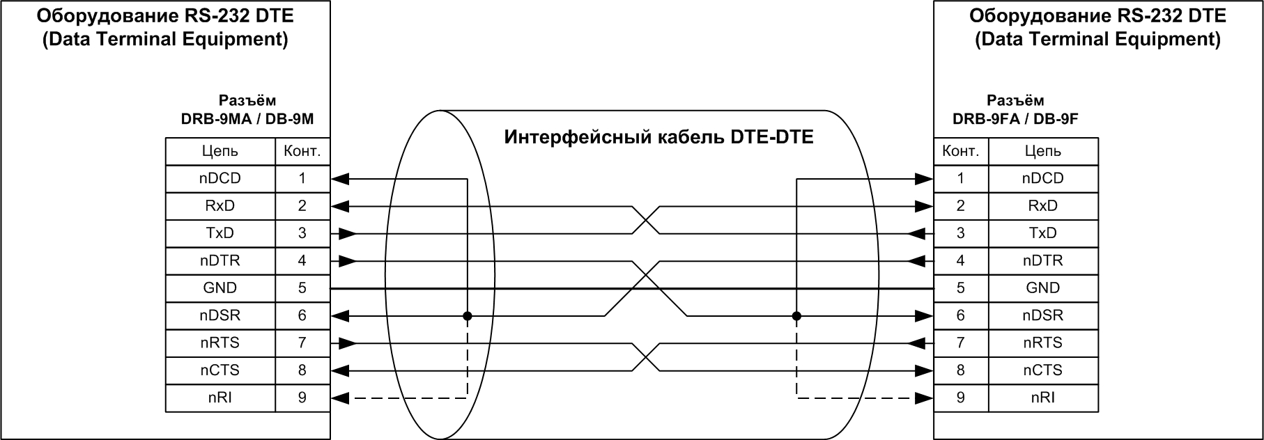
Fig. 6. Connection diagram of a zero-modem cable via RS-232 interface
In most modern RS-232 interface adapters, the DRB-9MA angled plugs are used as external connectors for mounting on a printed circuit board and fixing them in the mounting bracket to the housing. In multi-port adapters, additional straps are used with DB-9M connectors fixed on them, to which flat cables with a 1.27 mm pitch are soldered with pressed-in IDC-10 sockets at the ends, fig. 7
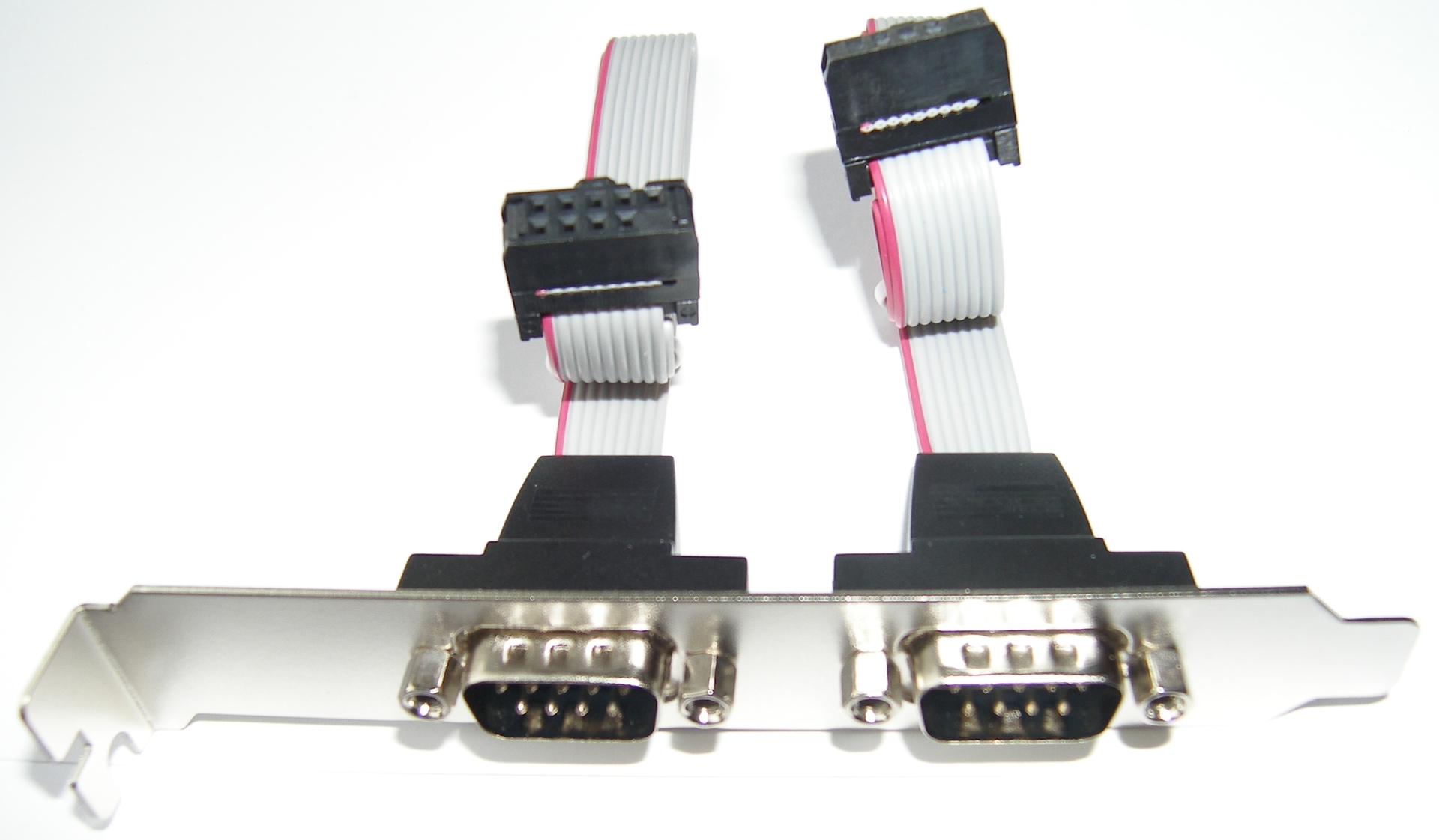
Fig. 7. Additional bracket with DB-9M connectors
IDC-10 jacks have one blind hole in place of the tenth contact, which serves as a key. The counterpart on the controller PCB is a PLD-10 pin connector with the tenth contact removed. The connectors for connecting two additional brackets are visible on the back of the adapter board FG-PIO9845-6S-01-CT01 shown in fig. 2
It should be noted that the wiring of the PLD-10 pin connectors on most RS-232 adapters is unified so that the first pin of the IDC-10 socket on the cable of the additional strap is connected to the first pin of the external connector DB-9M, the second pin of the IDC-10 socket DB-9M connector pins, etc. Thus, the pinout of pin connectors by pin numbers repeats the pinout of external DB-9M connectors (Fig. 8). The corresponding pinout of the DB-9M connector is shown in fig. 10 (the first contact is the red wire of the loop).
img src = " habrastorage.org/files/658/f59/b3c/658f59b3c3614cf68e2b2358a506fe0c.jpg " />
Fig. 8. RS-232 signal distribution on the PLD-10 male connector
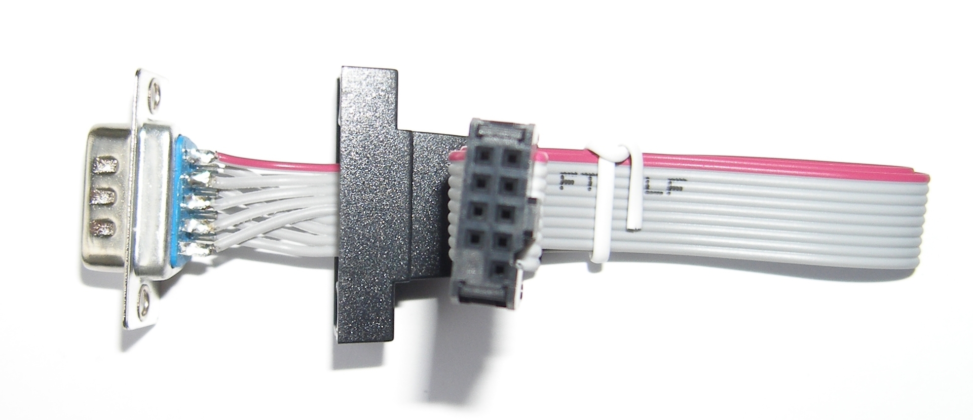
Fig. 9. Wiring DB-9M connector
The physical RS-232 interface both on the interface adapters and on the motherboards is traditionally implemented by the GD75232 level converter chip, or its full analogue SN75185 [6, 7]. These chips contain 3 bipolar RS-232 drivers for the TxD, nDTR, and nRTS circuits and five RS-232 level transducers to the TTL signal. Each chip GD75232 / SN75185 uses three power supply potential: VSS - minus 12V, VCC - 5V and VDD - 12V. All voltages are measured relative to common zero - GND.
There is a traditional scheme for connecting a UART controller to an RS-232 port using a GD75232 / SN75185 chip; it is presented in fig. 10. It is this circuit that is implemented in most RS-232 interface adapters, including on Espada boards.
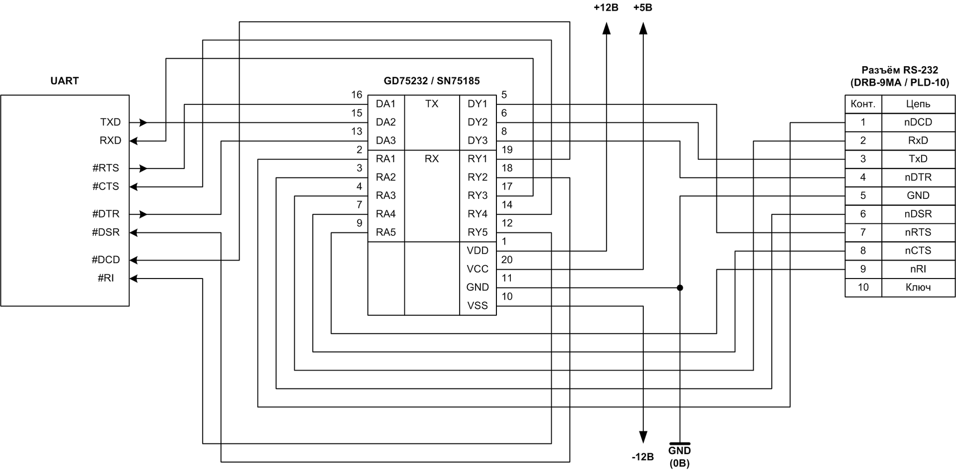
Fig. 10. Connection of the UART controller to the RS-232 port
The RS-422 physical interface is regulated by the TIA / EIA-422 standard defining the levels and waveforms of differential signals, allowing data to be transmitted over twisted pairs of wires at speeds up to 10 Mbaud (bandwidth depends on the interface width and data encoding method).
An example of using RS-422 signals in parallel interfaces is the “high-voltage” Differential SCSI interface (HVD - High-Voltage Differential).
Serial asynchronous interfaces UART in industrial equipment also often use the physical interface RS-422. In contrast to the differential RS-485 interface common in industrial and special equipment, the RS-422 physical interface is focused on the topology of point-to-point connections.
Using the physical RS-422 interface instead of RS-232 in serial ports allows you to increase the data transfer rate on short connections, or significantly increase the communication range of a single connection.
Realizations of the UART interface with the RS-422 physical layer in most cases use four pairs of wires: two pairs for data transmission in the forward and reverse directions and two pairs for the auxiliary RTS-CTS signals. A diagram of the connection of two devices via an RS-422 serial interface working via the UART protocol is shown in fig. eleven.
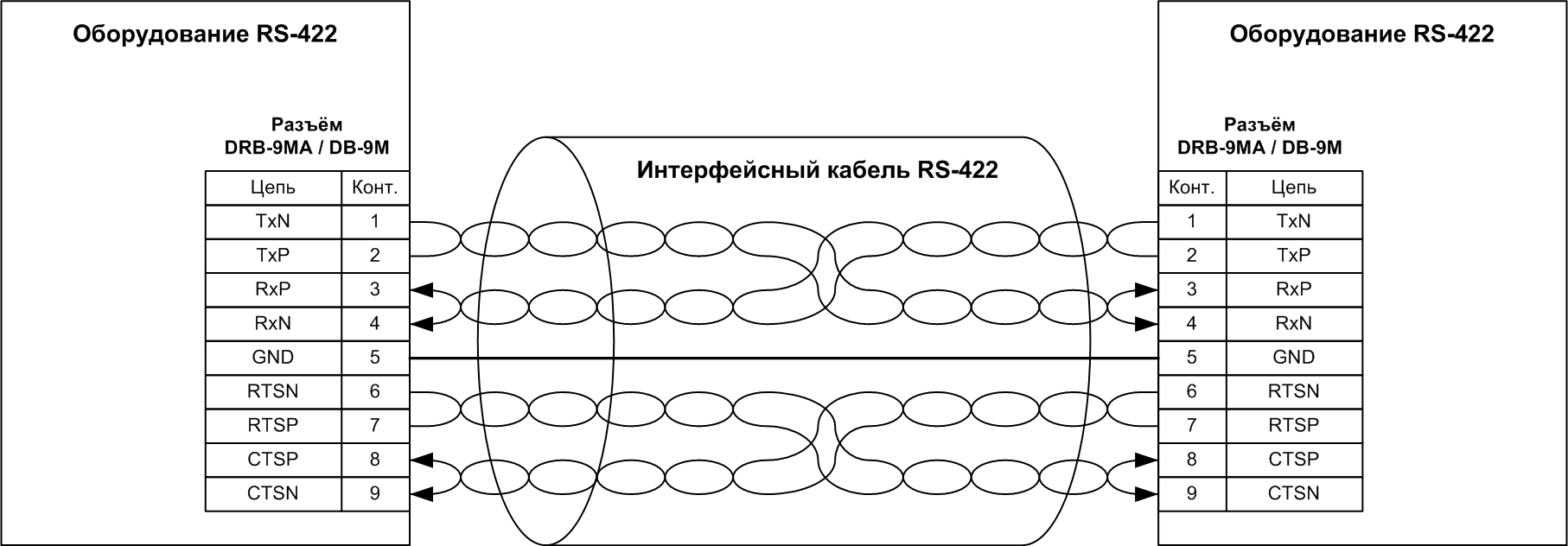
Fig. 11. RS-422 serial connection diagram
There is no single unified wiring for differential RS-422 signals in the DB-9 connectors for serial ports. It is proposed to consider the wiring implemented by Advantech in the PCL-743 adapter (Fig. 1), shown in Fig. 12.
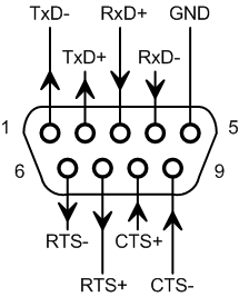
Fig. 12. DB-9M connector wiring for RS-422 interface
Re-equipment of serial port adapters to implement the RS-422 interface is proposed to be performed in the following way:
1. dismantle the RS-232 level converter chips,
2. Connect the following UART controller signals to the PLD-10 pin connectors: TxD, RxD, nRTS, nCTS.
3. To inputs nDCD and nDSR of the UART controller, apply a low level (GND), and to the nRI input - a high level (+ 5V), or connect the signals of the UART controller: nDTR-nDSR-nDCD-nRI,
4. on pins 1 and 9 of the pin connector PLD-10, apply the + 5V potential to power the RS-422 transceivers,
5. on the pin connectors PLD-10 of the adapter, install the RS-422 transceiver module, to which the IDC-10 sockets are connected to the plugs from the DB-9M connectors installed on the bar,
6. Connect pins 4 and 6 of the PLD-10 connector to the GND circuit.
Schematically, the principle of the described adapter upgrade reflects fig. 13.
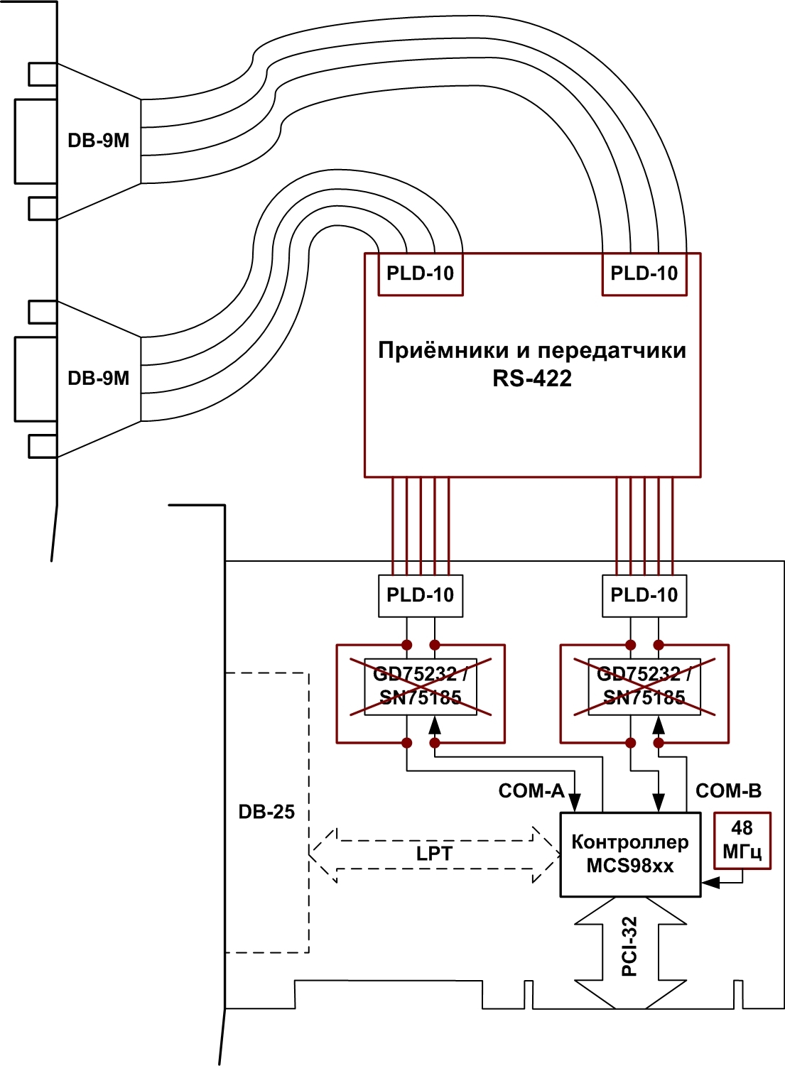
Fig. 13. Conversion of RS-232 adapter for RS-422 interface
PLD-10 . 14.
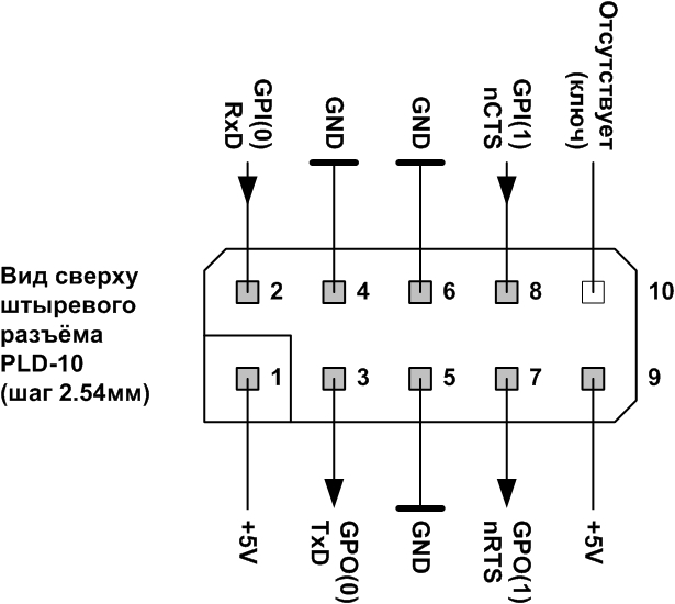
Fig. 14. UART PLD-10
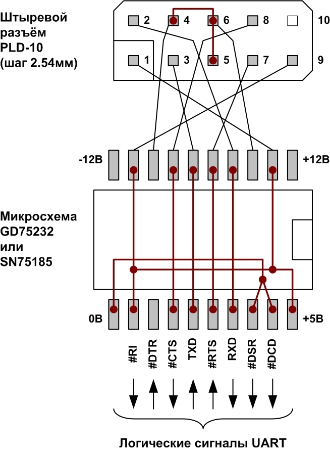
, GD75232 / SN75185. nDTR, nDSR, nDCD, nRI UART . 15. Espada FG-PIO9820 FG-PIO9835.

b
Fig. 15.
GD75232 / SN75185 (. 10), , . 15. FG-PIO9835-2S1P-01-CT01 GD75232 / SN75185 . 16. . 15, .15, . 17

Fig. 16. FG-PIO9835-2S1P-01-CT01 GD75232 / SN75185
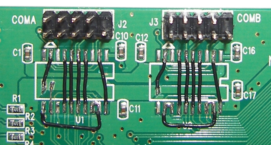
Fig. 17. FG-PIO9835-2S1P-01-CT01
- RS-422 AM26LS31C AM26LS33AC [9, 10]. - RS-422 . 18. PLD-10, , – PLD-10R .
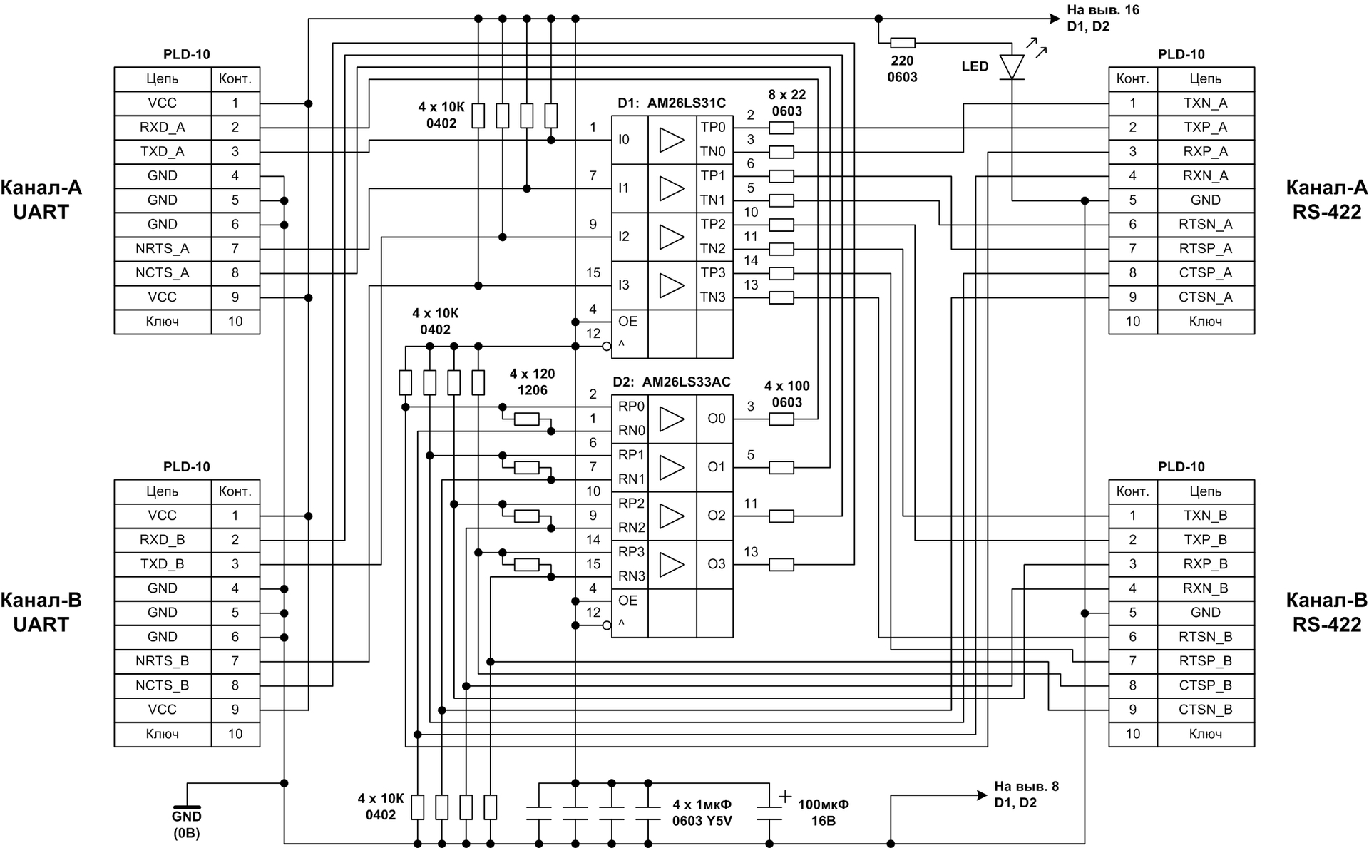
Fig. 18. - RS-422
, - RS-422 , . 18, . 19. AM26LS SOIC-16, -, . 5 6 8 . 1206 .
, , . PLD-10, .
120 1206 , . 10 .
100 UART, 5 .
22 . , 0603.
Espada.
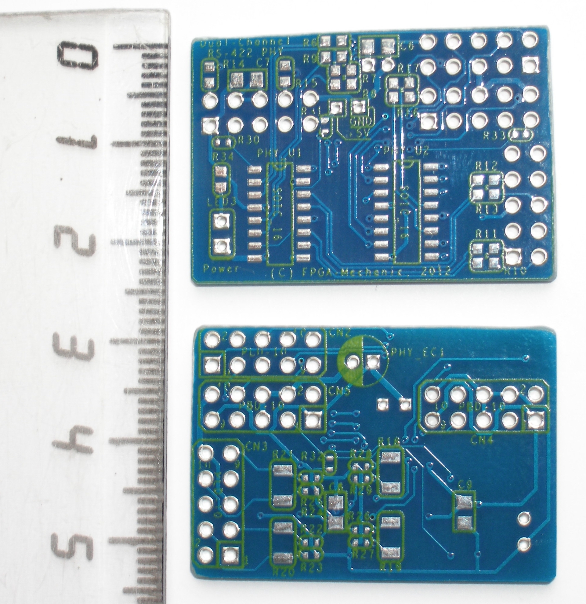
Fig. 19. - RS-422
- RS-422 , 2,5 2,54 , AM26LS31 AM26LS33 DIP-16. , . 19, . .
- RS-422 .20 ( ) . 21 ( ).
22 , 120 1206 . UART. , MCS9820. Espada FG-PIO9820-1S-01-CT01 . 22

Fig. 20. - RS-422
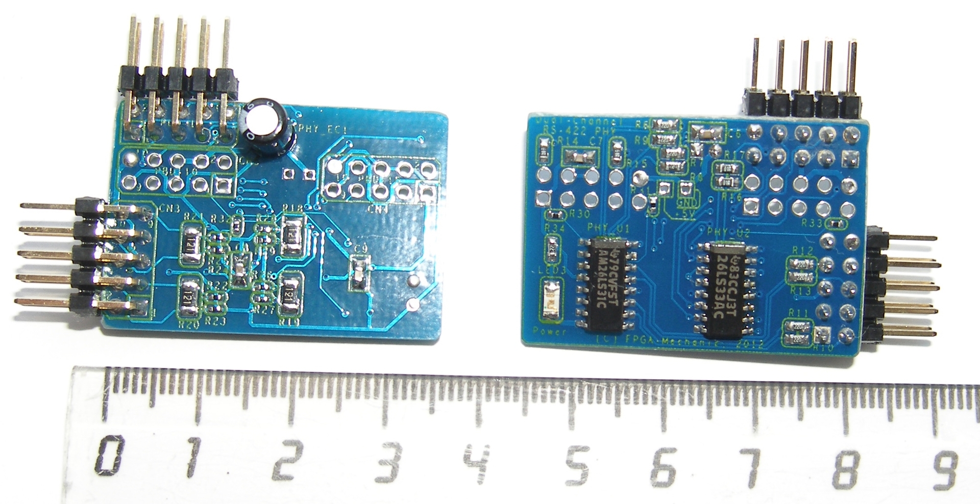
Fig. 21. - RS-422
, AM26LS31 AM26LS33 . .
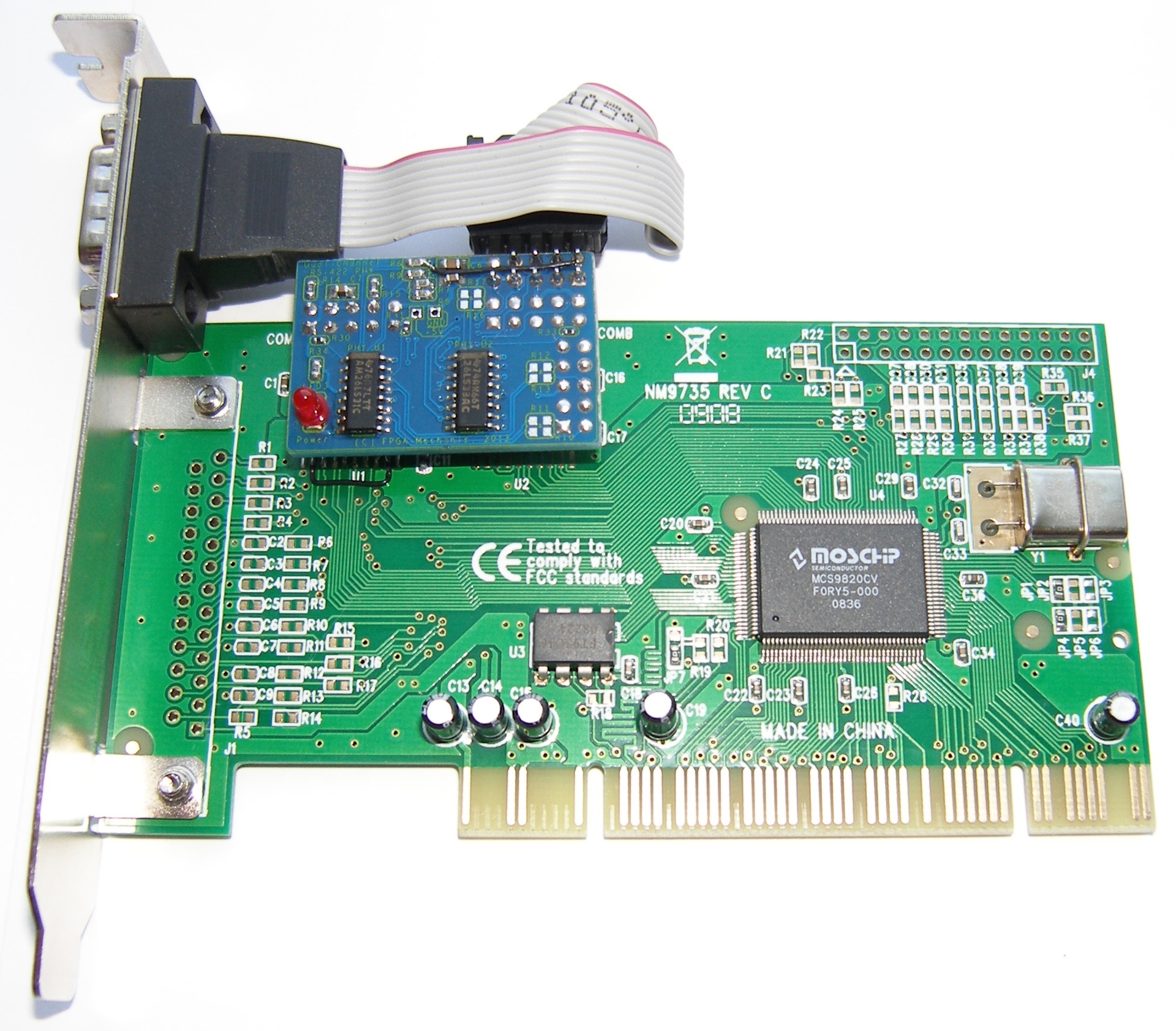
Fig. 22. RS422
- RS-422 , MCS9835. Espada FG-PIO9835-2S-01-CT01 FG-PIO9835-2S1P-01-CT01. Espada FG-PIO9835-2S1P -01-CT01 . 23.

Fig. 23. RS422
Espada Microsoft Windows (. 24). UTP (-), , TxD RxD RTS CTS. UTP . TxD-RxD RxD-TxD, – RTS-CTS CTS-RTS. RS-422 , , , . . - . AM26LS33AC 15 .
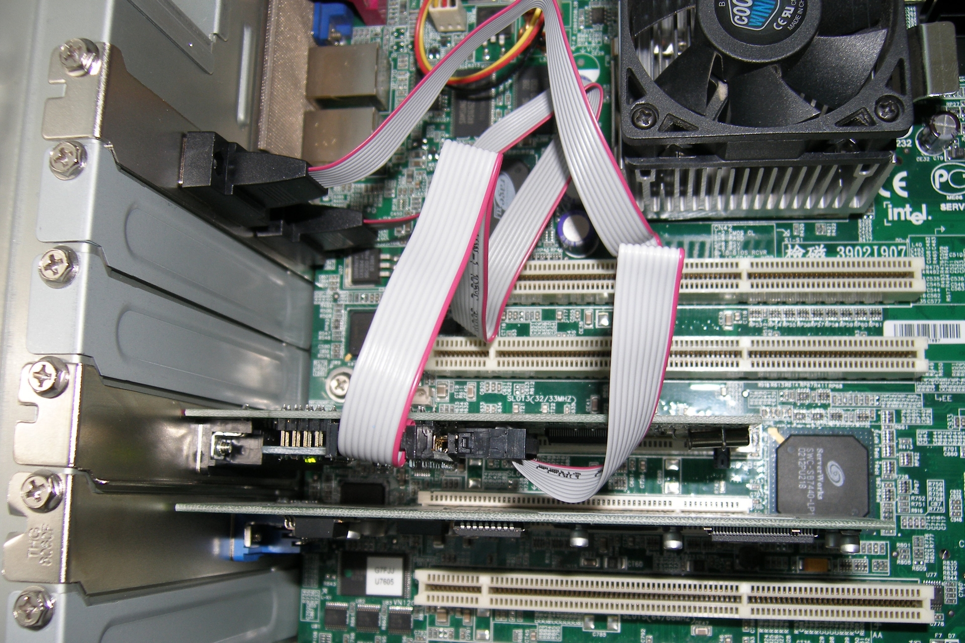
Fig. 24. RS-422
DB-9F, D-Sub (. 25). : 1-4, 2-3, 6-9, 7-8.
115,2 , 1 ( ).
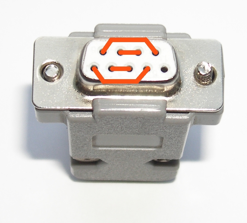
Fig. 25.
MosChip PCI 33. 66 (66,667, 15) . Espada FG-PMIO-B1T-0001S-1-CT01. SB16C1052PCI SystemBase [8].
SystemBase SB16C1052PCI (Target) 32- PCI 66 FIFO : 256 16 16C550.
RS-422 FG-PMIO-B1T-0001S-1-CT01. RS-232 . RJ6 2-3 UART SB16C1052PCI, U3. R19 9 ( nRI) 9 U3 (. 26). RS-232 J2 . 10. , , . 15 J2, UART , . 14.
FG-PMIO-B1T-0001S-1-CT01 - RS-422 . 27. DB-9M , IDC-10 (. 9). DB-9M .
RS-232 RS-422. .
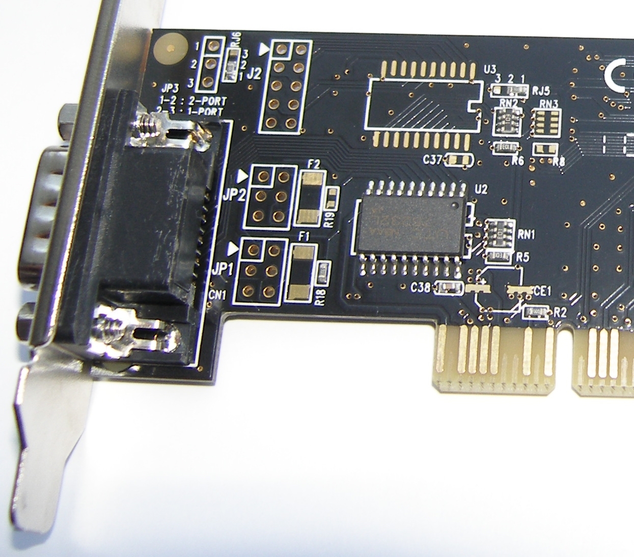
Fig. 26. RS-232 FG-PMIO-B1T-0001S-1-CT01
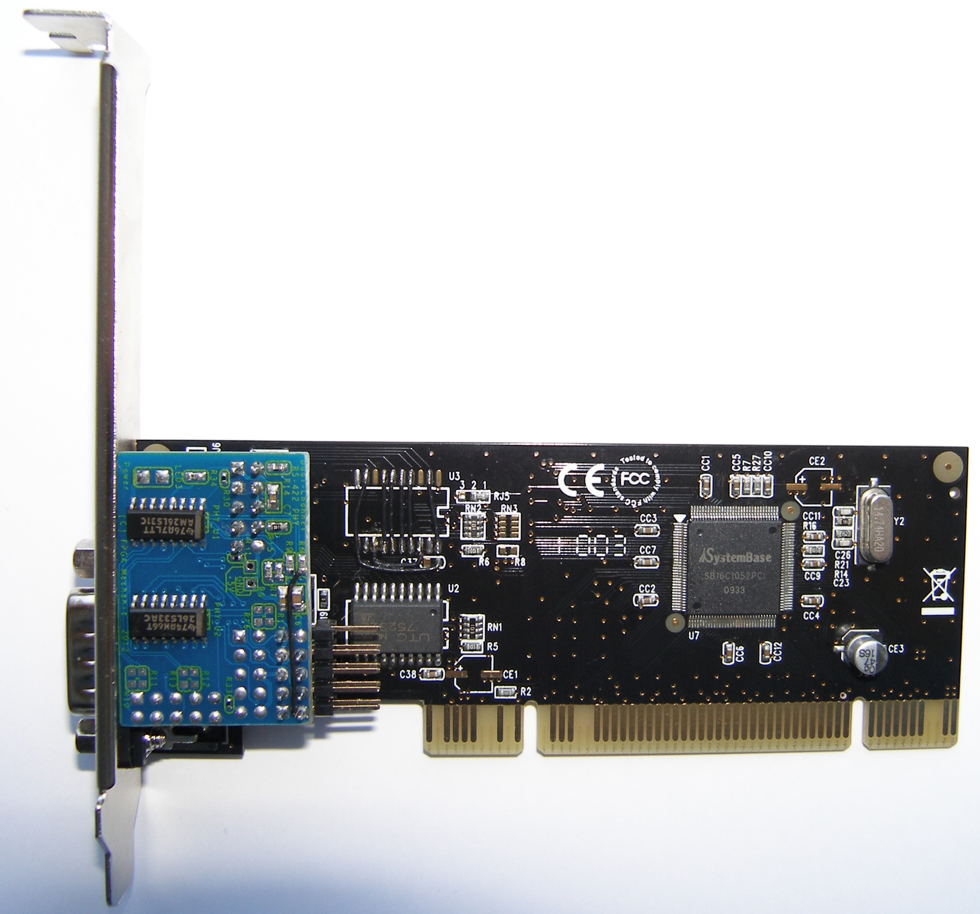
Fig. 27. FG-PMIO-B1T-0001S-1-CT01
findings
• RS-422 , 1 , RS-232.
• MSC98xx MosChip 1 , .
• RS-422 , . - RS-422 34 .
• RS-422 UTP FTP 100 .
Quoted literature
1. MCS9820 PCI Single UART. Datasheet Rev. 2.0. MosChip Semiconductor, 22 May 2006.
2. MCS9835 PCI Dual UART with Printer Port. Datasheet Rev. 2.0. MosChip Semiconductor, 22 May 2006.
3. MCS9820 PCI Single UART. Datasheet Rev. 2.4. MosChip Semiconductor, 29 July 2007.
4. MCS9835 PCI Dual UART with Printer Port. Datasheet Rev. 2.4. MosChip Semiconductor, 31 July 2007.
5. PCI Local Bus Specification. Revision 3.0. – PCI Special Interest Group, 2002. – 344.
6. GD65232, GD75232 Multiple RS-232 drivers and receivers. Texas Instruments SLLS206J. MAY 1995, REVISED NOVEMBER 2004.
7. SN75185 Multiple RS-232 drivers and receivers. Texas Instruments SLLS181D. DECEMBER 1994, REVISED JANUARY 2006.
8. SB16C1052PCI PCI Target Interface Controller with Dual UART. Datasheet Revision 1.00. SystemBase Co., Ltd. July 2009.
9. AM26LS31C, AM26LS31M Quadruple differential line driver. Texas Instruments SLLS114I. JANUARY 1979, REVISED FEBRUARY 2006.
10. AM26LS32AC, AM26LS32AI, AM26LS32AM, AM26LS33AC, AM26LS33AM Quadruple differential line receivers. Texas Instruments SLLS115D. OCTOBER 1980, REVISED MARCH 2002.
Source: https://habr.com/ru/post/306108/
All Articles