ZigBee wireless networks. Part 2 [Working with ETRX35X radio modules]
Introduction

In the last article , the main features of ZigBee wireless technology were discussed. In this part we will talk about how to quickly start working with this technology in practice. For this purpose, the ETRX357 modules were selected, which have built-in firmware that allows you to work with network functions and control analog and digital peripherals using a set of AT commands. Also, the article will discuss in more detail the issues related to the types of devices in the ZigBee network and network security. At the end, we will collect a data collection network that will receive temperature information from several wireless devices.
1. Modules ETRX357
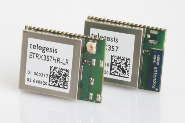
Let's get acquainted with the selected hardware platform. The ETRX357 modules are based on the EM357 chip from Silicon Labs. This microcircuit is a system-on-a-chip — the Cortex-M3 processor core — a RF transceiver operating at 2.4 GHz.
ETRX357 modules are available in 4 versions:
- ETRX357 - module with integrated chip antenna. The maximum radio signal output power is +8 dBm.
- The ETRX357HR is a module with a u.FL connector for connecting an external antenna. The maximum radio signal output power is +8 dBm.
- The ETRX357-LRS is a module with an integrated antenna chip and an integrated power amplifier. The maximum radio signal output power is +20 dBm.
- The ETRX357HR-LRS is a module with a u.FL connector for connecting an external antenna and a built-in power amplifier. The maximum radio signal output power is +20 dBm.
Experimental measurements of the communication range for the ETRX357 and ETRX357-LRS modules in direct visibility conditions:
- ETRX357 - confident reception at a distance of ~ 300 meters
- ETRX357-LRS - confident reception at a distance of ~ 900 meters
Below is a summary table of the main characteristics of the module:
| Specifications | Description |
|---|---|
| CPU core | ARM Cortex-M3 |
| RF transceiver | 2.4 GHz |
| Flash / RAM volume, Kb | 192/12 |
| power usage | TX: 42 mA @ +8 dBm |
| RX: 26.5 mA | |
| "Dream": 400 nA | |
| Working voltage range | 2.1 - 3.6 V |
| Operating temperature range | -40 ... + 85 ° C |
More detailed information on the technical characteristics can be obtained in the documentation for the modules [ 1 ].
2. Firmware
All modules come with firmware from the manufacturer, and to get started, just power up the module, connect the TxD and RxD lines of the UART serial interface, through which the module communicates with AT commands. All teams can be divided into 2 types:
- Work with network functions. For example:
- Networking / connecting to an existing network
- Sending targeted / multicast / broadcast messages
- Read / write remote node registers
- Work with the periphery of the module. For example:
- Configure I / O Ports
- RF transceiver power control
- Enable / disable the output of information messages on the serial interface
Also, the standard firmware includes a set of functions, which allow in some cases to do without an external microcontroller or control device. A complete list of commands can be found in the manual [ 2 ], only the most frequently used ones are listed below. We will need some of the commands in this list to create our data collection system.
| Team | Description |
|---|---|
| AT + PANSCAN | Scan the air for available networks |
| AT + EN | Networking |
| AT + JN | Connect to any available network |
| AT + DASSL | Leave current network |
| AT + DASSR: <device address> | Send a command to the remote device to exit the network |
| Team | Description |
|---|---|
| AT + UCAST: <device address> = <message> | Sending an address message |
| AT + MCAST: <max. the number of relays>, <group ID>, <message> | Networking |
| AT + BCAST: <max. number of retransmissions>, <message> | Connect to any available network |
| AT + SCAST: <message> | Send data to Sink-site |
Maximum message length : 72 bytes.
Important : multicast messages are a special case of broadcast messages, so do not send them with a high repetition rate (the documentation indicates no more than 8 multicast / broadcast messages within 8 seconds). In addition, it is worth paying attention to the fact that multicast messages are not accepted by sleeping end devices.
| Team | Description |
|---|---|
| ATSXX? | Reading the contents of the SXX register |
| ATSXX = YYYY | Writing to the SXX register value YYYY |
| ATREMS: <device address>, XX? | Reading the contents of the remote node's SXX register |
| ATREMS: <device address>, XX = YYYY | Writing to the SXX register of the remote node the value YYYY |
Bitwise access to embedded S-registers is possible. To do this, the read / write command, after XX, you need to specify the number of the bit to be addressed. For example:
ATS001? # 1 S00 ATS001=1 # 1 1 S00 ATS1812? # 18 S18 ATREMS:0000,0AE? # 14 S0A 0000 
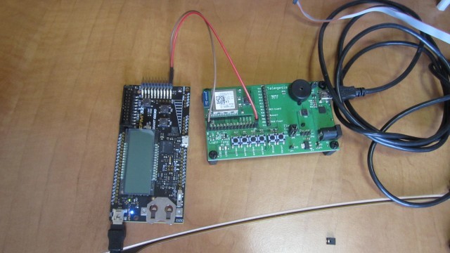
We now turn to a more detailed consideration of the process of building a ZigBee network. We will work with the debug boards on which the mezzanine radio module and the ZigBee USB gateway are installed. There are several analog sensors on the debug boards, which will be discussed later. We will take readings from them and send them to the central data collection center, where all this will be processed. Step by step, we will create our data collection system and analyze the main difficulties that may arise in the process.
We describe the future data collection system:
- The ZigBee USB Gateway is the network coordinator and is connected to the PC.
- The ZigBee USB Gateway is the central data collection hub.
- Two radio modules collect the data from the temperature and light sensor and transmit them to the central data collection center every 10 seconds.
- On the PC, a program is running that converts the digitized temperature values to degrees Celsius and outputs to the console.

3. Creating a ZigBee Network
Above, the AT + EN command was mentioned, which allows you to organize a network. The device to which this command was sent over the serial interface becomes the network coordinator. By default, the coordinator independently selects the most suitable frequency channel, generates a short and long network address.
AT+EN JPAN:24,949D,56370DE37E0DC0FF # 24 - # 949D - # 56370DE37E0DC0FF - Below is a list of registers, the value of which affects the process of creating a ZigBee network:
Channel Mask - Register S00 . This mask determines which channels can be used. Recall, the ZigBee technology specification defines 16 frequency channels (numbering from 11 to 26). The register is 2 byte, so by setting 0/1, you can enable / disable the use of the corresponding channel. This setting is valid both for the coordinator when creating a network, and for all other devices that want to join an available network.
ExampleATS00=0001 # 11 ATS00=FFFF #
Transceiver output power - register S01 . This parameter applies to the radio when creating a network or connecting to an available network, and is valid for the entire time the device is on the network. In the process of working in the ZigBee network, this parameter cannot be changed. The only way to do this is to leave the network, change the value in the register to a new one, leave the network and reconnect. All possible values that can be written to the register S01 are listed in the documentation [2].
ExampleATS01=8 # +8 # ( ETRX357. LRS- # )
- Preferred values for short and long identifiers are registers S02 and S03 . By default, the registers are written 0. For the coordinator, this means that when the network is organized, it will automatically generate the appropriate values. For all other devices - connect to any available network. Otherwise, if the value of the registers is different from 0, then the following rules apply:
- the coordinator will try to assign the appropriate identifiers to the new network
- all other devices will try to connect to the network with the specified identifiers
There is one important point for the coordinator: if you try to create a network with predefined identifiers, there is already a network with the same parameters, then matching identifiers will be generated automatically.
- The device type is the upper 4 bits in the S0A register. Types of devices will be discussed later. Now we say that the type of device is determined when connected to the network and can be changed in a similar way with a change in the output power of the transceiver.
4. Network security
In ZigBee networks, a special node, the Trust Center, is responsible for security. The default coordinator is the Trust Center. A trust center can also be any router (FFD device), if the network was created in the mode of a distributed trust center (this will be discussed at the end of this chapter).
List of responsibilities of the Trust Center:
- permission to connect other devices
- working with encryption keys (periodically updating keys, notifying other nodes about updating a key)
ZigBee networks use two keys:
- Link Key - this key is used to establish a secure connection between two devices on the network to exchange data. The key that the device receives at the time of connecting to the network is called the Trust Center Link Key, and all other keys that can be obtained during device operation are Application Layer Link Keys. By default, the Trust Center Link Key is transmitted in the clear, which represents a security hole, since this key can be intercepted when a new device is connected to the network.
- Network Key - this key is used to encrypt data on the network level of the ZigBee stack. It is generated by the Trust Center and updated periodically. All devices in a single ZigBee network have a single Network Key. It is used to encrypt all network packets. By default, the Trust Center transfers the Network Key encrypted using the Link Key
To prevent the potential compromise of data transmitted over the network, you can use several options:
- Transmit Link Key via non-standard communication channel / other communication protocol
- use the pre-installed key
- use the connection resolution mechanism on the side of the Trust Center (this method will not protect against compromise, but other people's devices will not be able to participate in the network accidentally or intentionally)
In this article we will look at the option with the Link Key preinstalled. The disadvantage of this approach is the need to write the appropriate configuration to all modules. But for our small network it is not critical. In the standard firmware of the modules, the ETRX357 Link Key can be set by writing the corresponding value to register S09 . In addition, the following bits must be set to 1 in the S0A register:
- bit 2 - setting to 1 forces the node to transmit the Network Key encrypted with the Link Key when trying to reconnect any devices
- bit 4 - - // - when trying to connect new nodes
- bit 8 - setting to 1 causes the node to use the preset Link Key
ATS09=ABCDEFFEDCBACBAFEDDEFABCBAFEDCFF:password # Link Key # :password - ATS0A8=1 ATS0A4=1 ATS0A2=1 Setting bits 2 and 4 on all nodes except the coordinator is an optional procedure. Advantages of this approach:
- There is no need to record the preferred identifier (short and / or long) of the network that the nodes will try to use to connect. Devices can only connect to a network with a Link Key installed.
- the attacker will not be able to get the Link Key, as it will not be transmitted in the clear
- to the network will not be able to connect the "alien" device
Let us point out another interesting possibility: in the S0A register, 9 bits are responsible for enabling a special function — create a network in the mode of a distributed Trust Center. In this mode of operation, any router (FFD device) can allow new devices to connect to the current network. Distributed Trust Center mode is used when deploying large networks to avoid delays in connecting all wireless nodes. After the network is deployed, a Trust Center is selected by AT + BECOMETC , which will manage security policy. To ensure the safety of the network in this mode of operation, it is also necessary to take care of the pre-installation / acquisition of the Link Key. Otherwise, until the Trust Center is selected, any ZigBee device will potentially be able to seamlessly connect to the network.
5. Types of ZigBee Devices
In the previous article , the main types of ZigBee devices were considered. Recall the main features and dwell on the types of end devices:
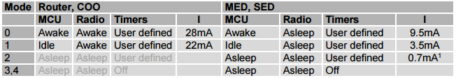
coordinator (COO) - the device that organized the network. Participates in the process of routing network traffic, performs the duties of the Trust Center (except in the case of the distributed Trust Center mode). Does not go into sleep mode, so this device must have a stationary power source
- A router (FFD) is a device that when connected was of the type FFD (full-featured device). Like the coordinator, such a device participates in the routing of network traffic, and all comments for the coordinator regarding the sleep mode are valid for the router.
The listed devices act as parent nodes for the end devices. The maximum number of child nodes at a router or coordinator can reach 32. Parent devices are responsible for receiving and storing (*) messages for end devices that are connected to them. The end devices, in turn, communicate with the network through parents. Each time a new end device connects to the network or when the old one reconnects, a parent is defined for it, which makes an entry in a special table of child devices. This table stores the short and long address of the child node and its type. Consider the available types of end devices:
end device (ZED) - a device that does not participate in the network's work in routing traffic, connecting new devices, etc. For this type, the ZigBee technology specification does not provide for a sleep mode. Therefore, when describing a parent (*) it meant that they do not store messages for ZED devices. It is assumed that the ZED device always includes the receiver and the parent node sends it to the addressee immediately after receiving the address message. So these devices must also have a stationary power source.
Sleeping End Device (SED) - Network duties for this type of device are similar to the previous type. The only difference is in the support for sleep mode, which is announced in the ZigBee technology specification. Such devices spend most of their time in sleep mode and can operate on a battery-powered power supply for a long time. The definition of “long time” here depends on the application, but if we consider the example of a wireless ZigBee switch, the lifetime of such a device from one set of disk batteries can be 2-3 years [3]. Such devices come out of sleep mode only by some external event (by a timer interrupt, in order to digitize the sensor readings; by pressing a button, etc.) or when it is time to send a data packet. In order to receive messages from the parent node, sleeping nodes use the Polling mechanism . We will talk about it a bit later.
- Mobile end device (MED) is an analogue of a sleeping end device (SED), with the only exception that the record about it is stored in the child table of the parent node for a short time - from several seconds to several minutes (for a sleeping end device, the record storage time can be up to 48 days). This is done, based on the type name, so that such a device can move around the room / object without causing collisions when sending a message. A collision may occur if several parents have an entry for the same node. This type of device is not described in the ZigBee specification and is a type of extension of the functions of the SED device in the implementation of the ZigBee stack from Silicon Labs.
ZigBee Network Example

End devices are always connected via an FFD device, which at the time of connection had the best indicator of the quality of communication. In the process of work, a situation may arise when the router has failed or it has been taken for service. In this case, after several attempts to reconnect with the parent, the end device will start searching for a new parent node. In the figure, the connection between the mobile node and the parent is indicated by a dotted line. After a certain period of time, the MED device can join the network through another parent.
Polling mechanism
This mechanism is used for several purposes:
Mobile and end devices can thus receive messages that are stored for them in the parent node.
- Preventing deletion of an entry about yourself from the child device table.
According to the ZigBee specification for sleeping end devices, address messages are stored by the parent ~ 7.68 seconds. Moreover, if the frequency of following address messages for SED / MED devices is higher than the specified value, then the messages will be overwritten. Therefore, to ensure reliable data delivery, the sleeping endpoint device must poll the parent node frequently enough. In this regard, there are two polling intervals for sleeping end devices: Short Poll and Long Poll intervals.
The Short Poll interval is used when waiting for confirmation of a successful transaction, for example, when sending a packet with data on sensor readings. Usually this interval is set to 1 second. After confirmation is received, the device goes into sleep mode and then the Long Poll interval is used.
Long poll interval is usually set in a fairly large - from several minutes to several days. This allows the sleeping end device to save space in the child table of the parent. A parent can delete the end device from its table if it has not been contacted in time. In this case, the end device that slept through its time must be reconnected to the network.
For more information about the Polling mechanism, see the ZigBee stack manual from Silicon Labs. In the standard firmware for ETRX357 modules, the parent node is polled by a timer / counter interrupt 0.
6. Creating a data collection network
The basic theory is told, let's move on to practice. A module in Python will be used to work with radio modules ETRX357. All recommendations for its use are given in the accompanying README file.
6.1 Configuring ZigBee Devices
We write in each node the appropriate configuration. All three devices — a USB gateway and two debug boards — were connected to a computer and each was configured accordingly:
- for the USB gateway, the coordinator branch ("COO") from the configuration file was used
- for modules on debug boards - a branch of sleeping end devices ("SED") from the configuration file
#!/usr/bin/env python3 # coding=utf-8 import rfconf import serial.tools.list_ports def main(): # sensor_nwk.xml configurator = rfconf.ModuleConfigReader("sensor_nwk.xml") supp_nodes = configurator.get_avail_nodes() supp_nodes = dict(enumerate(supp_nodes)) if len(supp_nodes) > 0: print("Configuration XML file support {} nodes:".format(len(supp_nodes))) print(supp_nodes) # "Telegesis" for com in serial.tools.list_ports.comports(): if com.description.split()[0] == "Telegesis": tgmodule = rfconf.ModuleInterface(com.device) usr_choice = int(input("How would you like to configure that node: ")) tgmodule.set_node_type(supp_nodes[usr_choice]) tgmodule.write_config(configurator) else: print("There is nothing to do") if __name__ == "__main__": main() <rfconfig> <node type="COO"> <!-- Link Key --> <reg name="S09" password="password" overwrite="y" type="string"> 12341234123412341234123412341234 </reg> <!-- --> <reg name="S0A" password="password" overwrite="n" type="hex"> 0114 </reg> <!-- --> <reg name="S01" overwrite="y" type="int"> 3 </reg> <!-- Sink- --> <reg name="S10" overwrite="n" type="hex"> 10 </reg> </node> <node type="SED"> <!-- Link Key --> <reg name="S09" password="password" overwrite="y" type="string"> 12341234123412341234123412341234 </reg> <!-- --> <reg name="S0A" password="password" overwrite="n" type="hex"> 0114 </reg> <!-- --> <reg name="S01" overwrite="y" type="int"> 3 </reg> <!-- Sink- --> <reg name="S10" overwrite="n" type="hex"> 100 </reg> <!-- PB5 --> <reg name="S15" overwrite="n" type="hex"> 2000 </reg> <!-- / --> <reg name="S13" overwrite="y" type="hex"> 00FF7EFB </reg> <reg name="S16" overwrite="y" type="hex"> 00008204 </reg> <!-- S16, --> <reg name="S17" overwrite="y" type="hex"> 00008204 </reg> <!-- / --> <reg name="S18" overwrite="y" type="hex"> 00FD58E7 </reg> <!-- S18, --> <reg name="S19" overwrite="y" type="hex"> 00FD58E7 </reg> <!-- / 7 --> <reg name="S37" overwrite="y" type="int"> 40 </reg> <reg name="S38" overwrite="y" type="hex"> 8110 </reg> <!-- --> <!-- 2 --> <reg name="S28" overwrite="y" type="int"> 0003 </reg> <!-- 0 1 (PA0) --> <reg name="S23" overwrite="y" type="hex"> 0001 </reg> <!-- 2 2 (PA1) --> <reg name="S24" overwrite="y" type="hex"> 0003 </reg> </node> </rfconfig> A few comments about setting up sleeping end devices. In order to minimize the power consumption of the radio module, you must turn off all unused peripherals: the LED display and the power of the light sensor. In addition, all unused pins must be configured to be configured with a pull-up or exit. Several 32-bit registers are responsible for configuring I / O ports:
- register S13 auxiliary register, which allows to determine the direction of the output (Hi-Z, input with pull-up, push-pull output, output with open collector)
- Register S16 configures a specific pin as an input (record 0) or as an output (record 1). The radiosodule has 3 ports A, B, C with 8 conclusions each. Recording settings can be made either by recording a separate bit, changing each output separately, or making changes at once for the whole group. The register is not non-volatile, so if you need a permanent application of a particular configuration, then it must be written to the register S17 . The value of this register is automatically transferred to the register when power is applied or when reset.
- Register S18 sets the logical level at the output of the output. , 0/1 . , 0/1 . S18 S16 . S19 , .
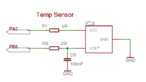
/ AT-[2]. , , , . , S15 13 1 ( PB5). LM61 .
6.2
, , , . . , . / 7 10 . / 7 S37. :

/ 7 S38 . 0110, /, Sink-. , , (S38F) S38 1. , – 8110. [3]. , Sink-.
Sink-
ZigBee (PANID). 0000 . , , , (UART, SPI ..) - . – , ETRX357, , . Disadvantages of this approach:
- :
- . ,
- :
- , .
, , ETRX357 — Sink- — . Sink-, 4 S10 . , , Sink, Sink, 8 S10 AT+SSINK Sink-. Sink- , , . , Sink-, . , Sink-, , . , , Sink- .
Sink AT+SCAST :
# Sink AT+SCAST:Hello # ( ) AT+UCAST:CAFE=Hello AT+UCAST:000D6F00024CBCCC=Hello 6.3
0, . - .
2 ( S28 ). , , 2-4, , UART. 0 , , . , UART ( . S11). 4 , . 1 2 ( PA0 PA1). :
# , 0 - 0001 # , 2 - 0003 # 2 ATS28=0003 # 0 1 ATS23=0001 # 2 2 ATS24=0003 :


, 1 , Polling-. , , . 1 . Polling- , .

6.4
, , . GitHub , examples , sensor_nwk.py . , . . . - , .
#!/usr/bin/env python3 # coding=utf-8 import rfconf import serial.threaded class TemperatureReader(rfconf.ETRXModuleReader): TEMP_POS = 2 NODEID_POS = 0 def handle_line(self, data): if not data: # return # : # SDATA: <Long ID>,<GPIO state>,<ADC0>,<ADC1>,<SeqNO>,<VCC> info, *payload = rfconf.response_split(data) if info == "SDATA": nodeid = payload[self.NODEID_POS] temp = int(payload[self.TEMP_POS], 16) # # LM61 temp = (temp / 10 - 600) / 10 print("Node: {} - Temperature: {:.2f}".format(nodeid, temp)) def leave_network(node): LEAVE_NWK_CMD = "AT+DASSL" node.write_command(LEAVE_NWK_CMD) resp = node.read_resp() # AT+DASSL "OK" # , "LeftPAN" if resp[-1] == "OK": msg = "" while not msg: msg = node.readline() print(msg) else: print(resp[-1]) def get_network_info(coordinator): NWK_INFO_POS = 1 GET_NWK_INFO_CMD = "AT+N" coordinator.write_command(GET_NWK_INFO_CMD) resp = coordinator.read_resp() if resp[-1] == "OK": nwk_info = resp[NWK_INFO_POS] *nused, ch, txpower, panid, longid = rfconf.response_split(nwk_info) print("network already created - ", end="") print("ch: {}, PANID: {}, EUI64: {}".format(ch, panid, longid)) def create_network(coordinator): NWK_INFO_POS = 1 NWK_PARAMS_POS = 1 CREATE_NWK_CMD = "AT+EN" coordinator.write_command(CREATE_NWK_CMD) resp = coordinator.read_resp() if resp[-1] == "OK": # nwk_info = resp[NWK_INFO_POS] info, ch, sid, lid = rfconf.response_split(nwk_info) print("network is created - ", end="") print("ch: {}, PANID: {}, EUI64: {}".format(ch, sid, lid)) else: # - , # get_network_info(coordinator) def main(): coo_node = rfconf.ETRXModule("<COMXX (Windows) /dev/<ttyUSBXX> (Linux)>", node_type="COO") reader = TemperatureReader(coo_node) # create_network(coo_node) ser = coo_node.get_serial_interface() reader_thread = serial.threaded.ReaderThread(ser, reader) # with reader_thread as protocol: reader_thread.join() if __name__ == "__main__": main() 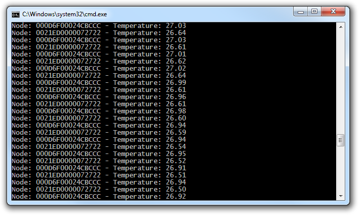
7.
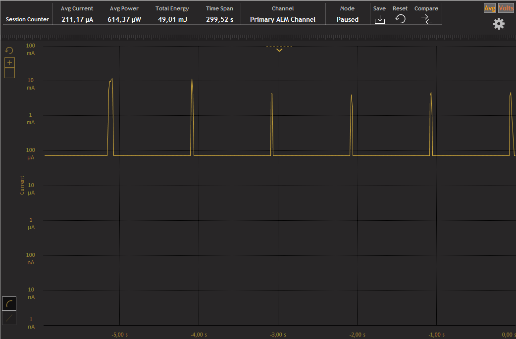
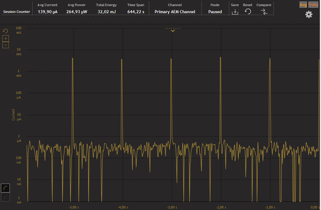
, . ZigBee- . , Polling- ~250 . 1 , 4000 (~160 ). , . , .
PS Energy Profiler, Simplicity Studio , EFM32GG-STK3700 Advanced Energy Monitor. Application Note Silicon Labs. , STK3700, . SWO .
Bibliography
- ETRX357
- AT- ETRX357
- Description of a Silicon Labs ZigBee Battery Operated Switch
- Description of the debug kit ETRX3DVKA357
List of articles
- ZigBee wireless networks. Part 1 [introductory]
- ZigBee wireless networks. Part 2 [Working with ETRX35X radio modules]
useful links
- ZigBee technology video
- Python module for working with firmware ETRX357
')
Source: https://habr.com/ru/post/306062/
All Articles