Why doesn't Wi-Fi based positioning take off
Preface or "If we have Wi-Fi, but let's position it with the help of it!"
Now geo-positioning on the basis of GPS technology is used by everyone who has a smartphone. But as soon as a person enters the building, the GPS stops working (although the smartphone shows the coordinate, but with much less accuracy). On the one hand, it was not very desirable, on the other hand, and why not, there are practical tasks for this.
But if you look at what the market offers us, until you see an adequate solution that is ready to offer the consumer an affordable and fairly accurate solution at the same time.
In this article I will try to consider the technical aspects (not related to the applied applicability) of positioning based on Wi-Fi technology (this technology is most common indoors and is suitable for solving this problem) and analyze the reasons for failure in implementation.
At first sight
At first glance (and only!), The Wi-Fi infrastructure is very well suited for indoor positioning: it has a sufficient number of points with known coordinates (meaning Wi-Fi access points, then just TD), every smartphone has Wi-Fi inside. Fi adapter (Client). Now it is possible to calculate the distance between the TD and the Client and calculate the Client's location using trilateration.
')
To solve the trilateration problem, it is necessary to have measurements from at least three points with known coordinates. To calculate the distance, the client’s signal level on the TD is measured, or rather its attenuation (we can get this data from the Wi-Fi infrastructure, this is within the scope of the IEEE 802.11 standard). Attenuation is converted to a distance using the formula for signal propagation in open space (FSPL - free space path loss). Next, we recruit the required number of measurements. If the distance from one TD is known, then a circle of a known radius can be described around it. If the distance from the two TDs is known, then the determined location will be located at the intersection of two circles. The presence of the third measurement determines the point at the intersection of the three circles.
And now we can arrange the Wi-Fi client on the plane. The task is clear, the implementation is clear. Many manufacturers took up the implementation (in general, they began to do the right thing, I think). But unfortunately, there are still a lot of questions in this decision.
Main questions
1. The increase in the number of TD more than doubled compared with their usual number.
2. Poor positioning accuracy even in ideal conditions (about 10 meters). And the cardinally deteriorating accuracy in the case of at least a small neglect of some requirements.
3. Unpredictable frequency of updating Wi-Fi client position data.
Wi-Fi Positioning Requirements
• Direct visibility is desirable between the three TDs and the Client;
• The client should hear well at least three TDs (and not one, which is usually enough);
• Hearing “good”, this is -75dBm and more, and this is not just “good”, it is very confident;
• Access points should be placed around the perimeter of the building and in a staggered manner;
• Wi-Fi client should not be very silent.
Why are such stringent demands being made and what threatens us if we do not satisfy these stringent requirements?
Direct visibility is desirable between the three TDs and the Client.
Perhaps the main problem that developers of indoor positioning algorithms had to face was a large number of signal reflections. This is the worst enemy of all positioning systems, which are based on measuring the propagation time or attenuation of the signal.
And what, for example, GPS? In GPS technology, we are dealing with a signal without reflections, with satellites in direct line of sight. This allows us to achieve very good positioning accuracy. As soon as GPS has to deal with a re-reflected signal, positioning accuracy catastrophically decreases.
Why it happens? Because we are actually measuring the length of the signal path (by counting the time delay or attenuation of the signal) and if it is reflected, then let it become longer than the actual distance. In the case of Wi-Fi indoors, we are always dealing with reflections. Moreover, all the main technologies of the IEEE 802.11n, 802.11ac standards (MIMO, MRC, BF) use this effect in their basis, without which they work worse.
For trilateration, this is very bad, the length of the path is measured with a large error, thereby increasing the overall positioning error.
Direct visibility can minimize the reflections and, therefore, reduce the error. Therefore, there is a recommendation to place the access point in the line of sight.
What does this requirement lead to? Such a requirement leads to a significant increase in TD, since within the framework of the usual coverage we only need one access point for 3-5 premises (the access points well “pierce” one / two non-capital walls).
The client should hear well at least three TDs (and not one, which is usually enough)
An ordinary Client has enough signal from one access point, it is obvious.
For positioning, a good signal level of three to four TDs is required.
Hearing “good” is -75dBm and more, and this is not just “good”, it is very confident
Take the official Cisco guide, which says that in order for the positioning accuracy to be about 10m in 90% of cases, the Wi-Fi client must “hear” at least three access points with a signal level at least -75dBm. Why precisely -75dBm and what happens if the signal is worse?
The fundamental role in the fact that the value of -75dBm, from my point of view, has the nature of the attenuation of the signal (the very FSPL). The signal decays not with a linear, but with a
The crucial role is played by the fact that the accuracy of the Wi-Fi receiver is very small, zero decimal places (signal level is measured in dBm), and the accuracy of power measurement in this case has a decisive role for the error of distance measurement.
For example, we can cite as an example the GPS technology, in which we have to use atomic frequencies, which ensure the accuracy of measuring the signal propagation time up to the seventh decimal place (measured in seconds). The seventh decimal place is an error of about 30 meters per meter.
Suppose that to achieve acceptable positioning accuracy, for Wi-Fi technology, the error per 1dBm should be no more than 10 meters.
To calculate the measurement error in meters per 1 dBm, I will take the FSPL formula and present it as a graph for clarity.
The formula for signal propagation for the 2.4GHz frequency can be summarized as follows:
FSPL = 32.4 + (20log10 (2,400)) + (20log10 (x)), where x is the distance in km.
FSPL = 100dB + 20log10 (x)
At the first meter, the signal level drops by 40dB, that is, the error is no more than 2.5 cm per dB. On the second meter, the drop is already at 6dB (the error is already 16 cm per dB), at the third - by 3.5dB (the error is 30 cm per dB).
The following graph shows the FSPL values along the X axis, while the Y axis shows the error values in meters per 1 dBm.
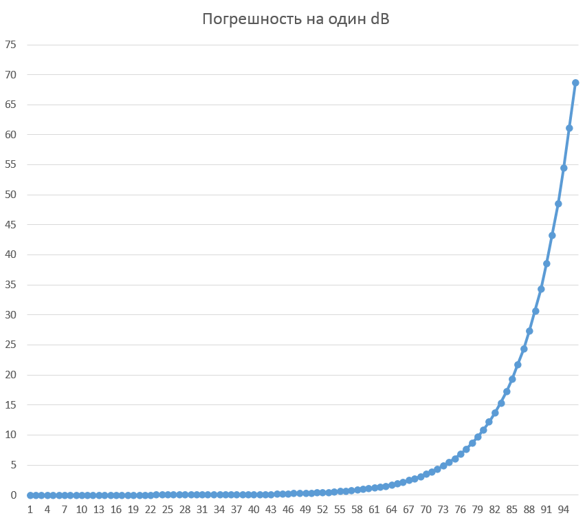
An error of 10m corresponds to a signal attenuation of 80dBm. Moreover, the error begins to increase sharply.
Take a modern AP with built-in antennas (5dBi), estimate its transmitter power under current conditions at 12mW (11dBm) and calculate the effective isotropic radiated power (EIRP) from which we subtract our FSPL.
EIRP-FSPL = 11dBm + 5dBi-80dB = -64dBm.
This is the desired signal level required to ensure acceptable positioning accuracy. Recall that Cisco general recommendations are 75dBm.
Considering that my calculation is very approximate, in general the values are very similar. In this case, the main idea is not to calculate a specific value (there are a lot of variables affecting this value), but to understand that with further attenuation of the signal, the positioning accuracy drops very sharply.
Surely the next question immediately arises, how much is it, -75dBm (or -64dBm), a lot or a little?
The speed of WiFi (modulation, which is used) depends primarily on the SNR (signal / noise), and not only on the signal level. In general, you can estimate the noise level inside buildings of the order of -95 - -90dBm (office space with several tenants). High speeds (MCS 5 modulations - MCS 7 (64 QAM)) require SNR values of 20 and above. This means that the signal level must be at least –75 - -70dBm.
That is, in other words, the -75dBm signal is a “confident” signal that provides high transmission rates.
And finally, the main conclusion is that at least three of these signals are needed for positioning, although in normal conditions one is enough, which inevitably affects the total number of APs.
Access points should be placed around the perimeter of the building and in a checkerboard pattern.
The trilateration error also depends on how the meters are located. On the meter there is information only about the distance to the object. When drawing circles, it is best to distribute them evenly over the surface, and also to be located, including at the perimeter.
In the case of GPS technology, all these issues are elegantly solved by the uniform distribution of satellites in Earth orbit.
If for Wi-Fi to arrange access points evenly inside the building is not so unusual (although sometimes it is very convenient to arrange three access points on one straight line in the corridor, which is contraindicated for positioning), then nobody places them around the perimeter, rather, on the contrary, try to avoid it because the coverage of the vast majority of office access points has a circular pattern and the location of the AP on the perimeter leads to incomplete use of the coverage of the access point and the output of the signal outside the building.
Frequency of indication
If we are dealing with specialized positioning systems, they care about the frequency of measurements. GPS satellites constantly transmit a signal, achieving positioning in real time (with quite a small delay, for example, sufficient for navigators).
The Wi-Fi infrastructure is not designed to solve the positioning problem and therefore there is no constant transmission of packets at equal intervals. Wi-Fi positioning systems have to work with the traffic that is. The more traffic, the better for positioning. But for Wi-Fi, everything is just the opposite. Throughout his adult life, the Wi-Fi community has been working on the task of reducing the client’s airtime, primarily to increase the overall Wi-Fi bandwidth, and secondly, to increase the lifetime of mobile devices. As a result, Wi-Fi positioning systems have to work with packages that come with unpredictable and often quite large intervals.
But even if the Client has transmitted a packet, this packet still needs to be detected by all necessary access points, which is not so easy for Wi-Fi. I will try to explain with an example.
Suppose the client sent a packet on the 1st channel of the 2.4 GHz band. It is in sight of three access points, according to the standard, they work on the 1st, 6th and 11th channels and if they do not transmit a signal, they should listen. The first point is the first channel, the second is the sixth, the third is the 11th. The first access point received this signal and measured its power. The second and third access points did not hear this packet, since they listened to the sixth and eleventh channels, respectively!
All this leads to the fact that the position update frequency is unpredictable and in some cases is very large, can reach several tens of seconds and sometimes minutes.
There are different ways to solve this issue. A typical access point spends a small portion of its time monitoring adjacent channels. But since this time is short and many channels have to be bypassed, the probability of “catching” such a package is still small.
Also, to solve this problem, additional radio is used on the TD operating in the monitoring mode, which uses all its time exclusively for monitoring and does not serve customers. But even despite this, there is a chance not to hear the required packet: in the 2.4 GHz band, you need to listen to 3 channels (sequentially) and 16 channels in 5 GHz. The task is slightly simplified, if we track the location of the connected devices, if the task is to track the position of all known devices, then it will be necessary to bypass the still unused channels (for example, all 13 channels in the 2.4 GHz band).
The conclusions are as follows: without the use of special monitoring modules and even with them, there may be a problem with the frequency of updating positions.
General conclusions
Good positioning requirements are largely at odds with the requirements for optimal coverage.
This leads to an increase in access points of at least two times, as well as to higher prices for TDs themselves (additional modules are needed). As a result, this leads to an increase in the budget for Wi-Fi infrastructure by two or more times. While as a result, the positioning accuracy does not exceed 10 meters, and the frequency of updates still turns out to be quite unpredictable, then these solutions, to put it mildly, are controversial and are implemented either in designated areas or with non-compliance with all necessary requirements with a known result.
But technologies do not stand still and in the next article I would like to try to analyze in detail the attempts to solve the above problems, and specifically:
- implementation of AoA (angle-of-arrival) technology in Wi-Fi using Cisco Hyperlocation as an example;
- an attempt to increase the frequency of position updates using a dedicated monitoring module using the example of Cisco FastLocation.
Source: https://habr.com/ru/post/306044/
All Articles