STM32F405: flash 400kb in 10 seconds or a fast UART bootloader sharpened for USB-UART, less than 4 kilobytes in size
With utility for PC and board - programmer,
using SPL,
with full command system and CRC32 verification,
with the guarantee of delivery and re-sending of a failed or lost team,
with error checking, debugging messages, and trimmed printf.
Optimized for modern USB-UART converters and streaming.
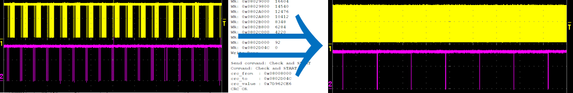
Table of contents
Prehistory
Analysis of the reasons for the low speed protocol AN3155
Requirements for my bootloader
Bootloader protocol description
PC Download Utility
UART Programmer based on CP2103
The implementation of the bootloader firmware
Size optimization
Outcome and Results
Prehistory
We use STM32 in almost all our devices. For example in our gateways .
In many devices, there is an STM32F405 / 407 and there is a USB <-> UART bridge based on CP2103, but sometimes FTDI.
According to AN3155, all STM32 have a built-in UART bootloader and we use it at all stages: from development and production to technical support of our users.
STM also offers PC utilities to use this protocol.
The CP2103 has a regular GPIO, which can be used to reset the device to the main program or to the regular bootloader.
Another good thing is that Windows does not touch these GPIOs when it searches for a Plug & Play device on an RS232, and therefore the device is not reset when connected to a PC and does not “fly away” into an incomprehensible mode for the user.
It would seem that everything is fine, but this regular bootloader has a tangible problem: it hurts too long: about two minutes, especially when you are debugging the circuitry, and not your code.
In this case, you usually make minimal edits and wait longer when done, have time to distract, and so on.
And it's not a matter of losing more than four hours per day on the firmware of a product, even though sometimes development lasts more than one month.
This problem of long firmware forced to look for the cause of the problem and begin to solve it.
And the solution presented in this article is the second attempt.
The first attempt was that I wrote my PC utility using AN3155 - "ARMkaProg".
She came an order of magnitude more convenient and smarter than the standard, was able to use the GPIO at the CP2103 and other hardware amenities.
But…
The standard utility and AN3155 did not recommend sewing at a speed above 115200 baud,
My own program could sew even 1000k baud, but it gave an increase to the speed of just 2 times (compared to 115200).
And not at 9, and as a result, the question of the speed of the firmware remained unresolved.
Analysis of the reasons for the low speed protocol AN3155
The low speed of the firmware stems from the specifics and simplicity of this protocol:
- The recommended maximum speed is 115200, but many USB bridges support at least megabytes, but at speeds above 115200 the protocol is activated from the tenth to the hundredth attempt, and each attempt is at least 300 to 500ms.
- It is necessary to erase the entire flash, even if the firmware size is 10k from the available 1024k bytes - in some crystals there were bugs with partial erasure.
- The regular bootloader is universal and, therefore, terribly slow, it does not use external quartz and does not use PLL and high frequency, and also noted that the flash is erased more slowly at a low clock speed - this is done for battery use.
- Small team size. A maximum of 1 time you can flash 256 bytes, and on some versions of chips no more than 128.
- A lot of extra gestures: you need to activate the bootloader, get lists of commands, for production you need to know the unique ChipID, it is not always possible to read it with one command and it is not always possible even from the bootloader.
- For security reasons, we always have any firmware locked, even temporary or debug. Although the unlock in fact is erasing, but you must do the full-time erasing procedure, because Nowhere does it say that the unlock is guaranteed to erase, but does not clog, for example, with garbage / zeros and so on. Therefore, it turns out that it is necessary to wash twice, and this is almost a minute!
- It is necessary to verify the firmware, i.e. Drive the firmware there twice: the first time to write, and the second time - read and check.
- The controller has a lot of RAM: 192k, but the bootloader does not use this, it is the same for all chips, including those that have very little RAM.
- Each team has three confirmations (ASC): the command code, the address and the data. But USB works at 1ms intervals, as a result, 3ms is spent for each command even if you need to read or write 1 byte, and we can send no more than 333 commands of the already scanty data blocks.
Let's take a closer look at the record command from the datasheet on AN3155:

where red marks: (1) - confirmation of the command code, (2) - confirmation of the address, (3) - data block
We look at the recording command with the oscilloscope (1000k baud rate)

and actually see these states of the ASC: (1), (2) and (3), and their noticeable delay from paragraph 9,
We also see that the recording time is huge and more time is spent on firmware than on data transfer (see item 3).
And if you look at a dozen write commands
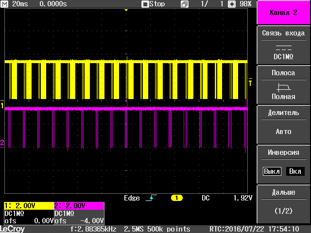
it can be seen that there are a lot of pauses and they take 2/3 of the time.
Hmm, what if you don’t wait for each command with three ACKs and just send the data as a stream?
But nothing good comes of it. The loader is so simple that it loses data if it is not waiting for it, there is no reception via DMA or interruption in it, and there is no ROM memory either so that everything is perfect for every interface.
From all these reasons logically follows:
Requirements for my bootloader
- Fixed UART speed at 921600 BOD: without a speed autodetection stage, which often fails.
- Partial deletion of selected pages.
- Work at the maximum clock frequency: use PLL and flash flash faster than new data arrives.
- Support commands with large data blocks, at least 2k bytes.
- There should not be any stages of activation type, you should immediately issue with one command everything you need: including ChipID and all options and versions.
- Ability to work in a locked chip, without unlocking it.
- Integrity check without reading to the host: for example, by sending and checking the CRC of the entire firmware.
- Using the entire RAM: while erasing is in progress, it is already possible to transfer at least as much as 100 kilobytes of firmware content.
- Do not require waiting for confirmation for each command. The incoming stream from the host should not depend on or wait for the output from the loader. The host can issue commands at maximum speed. And the loader should only report that the last successfully addressed address is such - that. And, in the event of a failure, the host could continue from this address. For example, TCP works in a similar way.
These items eliminate the corresponding causes of low speed.
But in practice we need more stuff:
- The starting point of the firmware and the entry point should be different: the first pages are convenient for organizing a pseudo-EEPROM and therefore usually the firmware code and its interrupt vector are not put there. And they start at offset 0x08010000 or further, i.e. in those pages that are long and erased.
- We need a state monitor and error text messages: I don’t like when there are no debug and status messages, since It's hard to debug the black box.
- The loader should be as small as possible : our devices are different and with different peripherals, but with a common board and common firmware, including all the loaders, the client code and the self-diagnostic code — all in one. As well as my loaders in one image, too many, my version of AN3155 with encryption, GPRS, full-fledged FSK-modem, and all of them must be able to fit into one or two first pages of 16-32k bytes. In the end, every byte counts.
- The loader must be reliable , in AN3155 command protection from failures and debris is weak - just the XOR of all bytes. There were several cases when she was faltering.
Bootloader protocol description
I decided to make a more detailed description of my protocol in case anyone wants to port the PC boot program to other operating systems than Windows.
General principle
- Two participants: Host and Device.
- The host is flashing the device.
- Host host and initiate the exchange.
- The device is slave.
- The exchange is made by teams.
- Commands are packaged.
- Packet Byte Order: Little endian
- One package - one team.
- One team - one action or event.
- The device responds to Host commands with the same command code as the host.
- The device generates, without a request, only emergency reboot and timeout commands.
- Each packet begins with a 32-bit signature beginning of the packet.
- Signatures are different for directions to and from the Device.
- The rest of the format is the same for both directions.
- Each package is protected by a CRC32 at the end of the package.
- The packet size in bytes must be a multiple of four.
- Timeout for a general reset of the Device to 500ms, the Host is obliged to ensure that there will be no pause more than 500ms.
- In addition to the commands, debugging text messages in bare ASCII can be issued from the Device, they should not start or contain the signature of the beginning of the package and should be displayed outside the package body.
Package structure:
| address | the size | content |
|---|---|---|
| 0 | four | The signature of the start of the command, for transfer to the device 0x817EA345, for receiving from the device 0x45A37E81 |
| four | one | command code, sets the type of action or event |
| five | one | bitwise inverse command code (for verification) |
| 6 | 2 | N - size of additional information in bytes ( must be a multiple of 4 ) |
| eight | N | additional information - depends on the command code |
| 8 + N | four | embedded hardware in the STM32 CRC32 packet from address 4 to N (excluding the signature) |
The signature of the beginning of the team for different directions is chosen different in order not to mistakenly perceive their own data, which came to him at the reception. For example, when there is a short circuit on the legs of the RX and TX controller or a programmer / cable failure.
Error handling at the level of packets and timeouts
- If the command code does not match the verification inverse code, then the beginning of the packet is not counted, and the search for a new command begins with the next byte.
- If a packet with the size of the additional information is larger than the internal buffer, then the packet is ignored, and the search for a new command begins with the following bytes after the size.
- If the CRC32 received in the package body is not equal to the actual calculated one, then the contents of the package are ignored and the search for a new command begins with the next byte after CRC32.
- If bytes arrive, but the signature of the start of the packet is not detected. Then these bytes should be considered debug text messages and accumulated to code 13 (line feed), and after this code should be output to the debug console.
- If more than 500 ms has passed since the last packet was received, the bootloader is reset to its original state. A packet that did not have time to be taken to the end is ignored and is also discarded. About timeout The device reports a packet with a special command code "timeout".
- When you start the bootloader, another package is generated with a special "reboot" code.
The operation of the device
- We answer the command information, and when resetting or timeout we notify the host about it.
- The firmware is recorded sequentially from the beginning of the free range to the end of the firmware or free space.
- The device contains the address of the current block to be recorded.
- By default, the address of the current block is set to 0, which means that the erase was not performed and the record is invalid.
- Erase command: erase how many requested are rounded to fit the page and reporting on each erased page.
- At the end of erasing, the address of the current block is set to the beginning of the free range - you can start recording.
- Write command: if the address of the received block is equal to the address of the current block, then we write it down and update the current address.
- Write command: if the address of the received block is NOT equal to the address of the current block, then ignore the record.
- In both cases, 6 and 7 are reported to the host address of the current block for recording.
- At the end of the recording, the Host must issue the "Start" command with the CRC32 of the entire firmware, and if it is correct, the firmware will start.
- If no commands were received within 5 seconds, then run the main firmware if it is there.
- If the timeout is 500ms or a hardware reset, the address of the current block for recording is reset to 0.
Hosting order
- We receive information from the device: flash size, ChipID, receive buffer size, start address, bootloader version and chip.
- We give the command to erase either the entire firmware, or part by specifying the size of the erased area.
- Upon completion of the erasing, we begin to continuously send writing commands in blocks one after another, checking that the current recorded position in the device is increasing.
- If the position has ceased to increase (accepted two responses to the "write" command with the same address), then correct the address on the Host, reset the send buffers and start transmitting from the new adjusted address.
- Upon completion of the recording, issue the "Start" command by transmitting the entire firmware CRC32, in response, the Device will report the actual CRC32.
- If the actual CRC32 is equal to the calculated one, then the download is successfully completed and the firmware is launched.
Command Description
In the description of the teams I will sign only the additional parameters of the command that follow the code and size of the parameters.
The command code is given in parentheses, then the constant in the source code and the name in Russian
Additional parameters of the command from the Host:
are missing.
Device response:
| size in bytes | Description |
|---|---|
| 12 | Unique ChipID |
| four | Model and chip revision, taken from DBGMCU-> IDCODE |
| 2 | Size of writeable flash loader in KiB (* 1024 bytes) |
| 2 | Bootloader version 0x0100 |
| four | The size of the device receive buffer (for the -PreWrite option) |
| four | Recordable start address |
| four | Address of the interrupt vector table and the place from which the launch context is taken (stack + entry point) |
example from logs:

Additional parameters of the command from the Host:
4 bytes - size of erasable area in bytes
Device response: issued at the end of erasing all pages,
4 bytes: If successful, then the size of the erased area is equal to what the Host transmitted. If a failure occurs, then 0.
During erasing device:
- Erases pages starting from # 1 and up to the required one, according to the size, rounded up.
- After erasing each page, it responds with the SFU_CMD_ERASE_PART command (“page erased”).
- It accumulates incoming commands in the receive buffer, but does not respond to them and processes it only after completion of the erase.
- The erase time of the first three pages is about 300 ms, followed by about 2 seconds.
example from logs:

The host should not issue a command with this code — it will be ignored.
During erasure, the host can transmit data in advance for writing with the SFU_CMD_WRITE (“write”) commands - to speed up writing.
But you can send commands no more than the size of the device receiving buffer, otherwise it will overflow and the first packets will be replaced with new ones, and the next ones will be ignored.
Command parameters from Device:
4 bytes: erased page number from # 1 to # 11.
Additional parameters of the command from the Host:
4 bytes - the address from which to write the contents.
X * 4 bytes is the contents of the firmware, where X is the number of 32 bit words and should be: 1 ... 1023.
The entry is ignored if the address specified by the Host is not equal to the current address of the entry in the device.
The device responds always regardless of whether the recording was made or ignored.
Device response:
4 bytes: the address of the next block to be written is incremented if the record is successful, does not change if the command is ignored
4 bytes: the amount of raw data in the device's receive buffer (for debugging and monitoring).
An example of responses from several successful "Record" commands from logs:

Additional parameters of the command from the Host:
4 bytes: CRC32 of all recorded firmware, the beginning of the firmware is indicated in the "Information" command, the end - the last recorded device confirmed by the command with the "write" command is the address of the next block to be written (not inclusive).
Device response:
4 bytes: The start address of the firmware.
4 bytes: The number of bytes written (Attention, not 32-bit words!) Is a multiple of four.
4 bytes: CRC32 for verification by the Host, calculated from the "Address of the beginning of the firmware," the size of the "Number of recorded bytes."
After this command, the Device checks the CRC32 and if it matches the one given by the Host, it launches the firmware by performing a full deinitialization of the equipment.
An example of the logs:

More than 500 ms has passed since the last command was received and the timeout has expired, the device has been reset to its original state.
Without parameters.
The host should not respond to it.
This alarm message is a command that only the device issues.
Writing to flash memory failed. This happens if the power supply is insufficient or fake Chinese chips like GD32F4xx.
Without parameters.
The host should not respond to it.
This alarm message is a command that only the device issues.
Hardware reset device. The device HARDWARE reset to its original state - the bootloader restarted.
Without parameters.
The host should not respond to it.
This alarm message is a command that only the device issues.
PC Download Utility
Appearance:

Written for Windows on Delphi 6 (2001, the one that has 8 bit char type and not unicode). Compiled on Delphi XE5 and tested performance. Such an old Delphi was chosen because it was easier for me: since the beginning of the 2000s, there have been great developments in working with CP210x, COM ports, and so on.
Work with the device at the byte level is allocated to a separate tCOMclient stream, independent of the delays of the visual interface. The connection to this separate stream is made using the read and write queues of 65,536 bytes.
The level of parsing with the design of commands and the logic level of working with commands is divided into two separate classes, tSFUcmd and tSFUboot.
The firmware is updated at a speed of 921600 baud, no parity, 8 bits, one stop bit.
Devices can be specified:
By the name of the COM port, for example COM123.
By serial number recorded in CP210x
On the system path WinNT, for example \ ?? \ USB # VID_10C4 & PID_EA60 # GM18_E_0010 # {a5dcbf10-6530-11d2-901f-00c04fb951ed}
In any case, if the open device is CP2103, then the utility can try to reset it via GPIO1 (18 pin), setting it to 0-1-0.
The kerchief programmer with its scheme is also attached and described below.
If running without command line parameters, it restores at startup and saves upon completion of the configuration from a text file: FastTest.exe.config
If command line parameters are present, the settings from this file are ignored and it is not changed. Instead, the settings in the visual components are taken from the command line and the firmware is started if indicated.
You can use the following command line parameters:
- Firmware specified without perfixes
- -DEV: <device_name> The device name or COM port is specified in <device_name>
- -reset or -RST reset the device if the COM port goes through CP2103.
- -fast fast erase, erase only those pages in which the firmware will be placed
- -exit Close the program upon completion if the firmware was successful or the -no-Errors-Keep option is specified
- -no-Errors-Keep close program on completion anyway
- -no-Prewrite Do not send data to write while erasing
- -go or -run or -start Start the firmware immediately after launching the application, otherwise the settings are applied, but the launch is not performed.
You can download from here:
https://github.com/Mirn/Boot_F4_fast_uart/tree/master/delphi/Release
UART Programmer based on CP2103
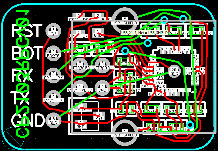
I post our small and simple programmer which:
- Uses for firmware at CP2103 UART and GPIO, only five wires: GND, TX, RX, BOOT, RST.
- They can sew all kinds of STM32 UART, and use my bootloader from this article.
- It has protection against hot plugging, and for all the time it has been used it has never burned (for now, I hope ...).
- Contacts are signed with silk-screen printing, which is very convenient (do not forget to order silk-screen printing in the top layer)
- Small, slightly larger than the USB connector.
- Included is the ConfigProg \ CP2102_Enum.exe utility for configuring GPIO in CP2103: select a device and click "USB write".
- ATTENTION: it is not electrically isolated.
Settings should be as follows:
IO.Mode = 1100001101010100 IO.Reset = 0000110011111111 IO.Suspend = 0000111111111111 IO.EnhFxn = 10 The FastTest utility from the previous chapter was developed and debugged on this programmer.

Source files on the programmer download from here:
https://github.com/Mirn/ProgCP2103
The implementation of the bootloader firmware
Development Tools and Third-Party Libraries:
- Wednesday: Eclipse Kepler Service Release 1
- Compiler: GCC v5.4 2016q2, with settings:
-mcpu=cortex-m4 -mthumb -mfloat-abi=hard -mfpu=fpv4-sp-d16 -Os -fmessage-length=0 -ffunction-sections -fdata-sections -ffreestanding -fno-builtin -Wunused -Wuninitialized -Wall -Wextra -Wpointer-arith -Wshadow -Wlogical-op -Waggregate-return -Wfloat-equal -Wno-sign-compare - Link and link using the ld file of the script with sections.
- A project is built using the Makefile utility; you can build it without an environment using the command make all
- The startup and initialization code is taken from CooIDE version 1.6, because it is minimal and known to me.
- STM peripheral library: standard peripheral library (SPL V1.3.0)
Memory Usage Profile:
- I placed the stack in a separate 65k CCM memory.
- The main ring buffer of reception from UART is 100 kilobytes located in a separate section at the beginning of the RAM
- All other buffers and variables located in .bss in the remaining 28k RAM.
Usart_mini.c library
It is made as simple as possible: DMA is not used, the transmission is made by direct sending to the periphery without interruption using SPL functions. But since the main purpose of speeding up the protocol is a continuous stream of commands with content for the firmware, the reception of data from the UART is done by interrupting the USART1_IRQHandler.
Also in the UART, I implemented the control and accounting of errors and checking and correction of the buffer in case of data overflow, if they are written more than its size.
When implementing UART reception in interrupts, a problem arose:
By default, the code is in flash and during flash memory flashing, the flash bus is blocked and execution stops completely including interrupts. And at speeds above 500k BOD, this leads to a loss of data received from the UART, since pause time becomes longer byte reception time. Therefore, the interrupt handling function was moved to RAM like this:
__attribute__ ((long_call, section(".data"))) void USART1_IRQHandler(void) at the same time there is an important subtlety that if a function lying in RAM causes other functions in the flash, we get an error of the form:
usart_mini.c: relocation truncated to fit: R_ARM_THM_CALL against symbol `demo' defined in .text.demo section in ./src/main.o This is caused by the restriction of the ARM architecture of Thumb2 instructions to the maximum address distance between calls. And in this case it is more than acceptable. I fixed this by adding the long_call attribute modifier to all functions called from RAM.
Library packet_receiver.c
Accepts packets according to the protocol described in this article and checks their integrity. At the same time, at all stages of parsing the package checks for errors and counts their number if they meet. But errors are not silenced, but text messages are output and a line with all errors, both UART and packet level and 500 ms time-out, is output once per second. This 500 ms timeout is controlled and generated by the same library.
Sfu_commands.s library
Handles command logic SFU_CMD_XXX as described above. It erases and flushes the flash, while the function of the firmware of the word in the flash memory is also rendered in RAM, so that data on reception from the UART is not lost. It also implements the launch of the main firmware, while checking that its context indicates the real flash memory and RAM memory. Before launching the main firmware, all peripherals and clocks are fully deinitialized and reset.
The performance of the firmware is tested on models: STM32F405RG, STM32F405VG,
and at speeds from 115200 to 921600 baud.
All firmware sources are available on my github under the link:
https://github.com/Mirn/Boot_F4_fast_uart
Option for STM32F7xx:
https://github.com/Mirn/Boot_F745_SFU
Size optimization
First and foremost, the size that affects the size is the overall architecture of the algorithm and the data used. I tried to do everything as simple as possible and, even in some places, primitive. At the same time I tried to shift the most difficult things in logic to Khost. In short, order and brevity in code begins with order in the head of the developer.
But you need to comply with the measure and do not forget about the amenities that help you better understand what is happening in the bootloader, and therefore there are debug messages, control and error counting and other trifles and amenities. And also I did not sculpt everything into one function and put everything on the shelves, and broke it into modules. Although this leads to an increase in the size of the firmware by a couple of hundred bytes, for many years I will have to maintain, develop and create new ones based on it. Another small contribution to the increase in size made it necessary to place some of the functions in RAM.
Also, do not forget how the compiler and its optimizer work. I compiled naturally on -Os, but did not use any other special keys and did not even bother with it. If you give more specifics, then the compiler will be able to better optimize: parameters to sign const where it is possible, local functions within one file as static, etc.
It is also not worth shamanizing with trifles such as rearranging strings, licking ifahs with boolean optimization of the conditions in them - all compilers have been able to do this for a long time. Trust them. In which case, you can look at the map file, where it says which function, how long it takes, or just count the number of lines in the listing. Without even knowing the ASMA, it will immediately show which function suddenly turned monstrously.
SPL optimization
The STM standard peripheral library has a very large downsizing potential. It is written very simply - many functions transfer data from the completed structures transferred to them to the corresponding peripheral registers. These functions do not contain internal static variables, do not access global variables, and usually do not require pointers to any state stores. They very rarely refer to their other or other people's functions. But they have a flaw: they contain a lot of duplicate code, for example GPIO_DeInit checks the equality of the transmitted GPIO to each port of the GPIOA, GPIOB ... GPIOI, and resets each port separately with a separate code. Those. there really is a bundle of ten if and twenty RCC_AHB1PeriphResetCmd. And so the SPL consumes a lot of flash. A bunch of UART and GPIO with RCC usually accounts for about 8 kilobytes.
Therefore, I copied the code of the used SPL functions into a separate header, declared them as static inline and added a _inline suffix to each such function, for example GPIO_DeInit_inline. Also zainlaynil all functions caused by them. This immediately reduced the code at times.
Optimization of the .data and .ro_data sections
The .data section stores the starting values of variables that are specified at the compilation stage. They are placed in a flash, and there is a loop in the code that copies them when launched into RAM.
I wrote the code so that there were no such variables at all, and I would not have to write code that manually sets the necessary parameters to them.
The .ro_data section stores all constants, including text constants. Here you just need to know the measure, and do not display poems in the terminal, limiting yourself to a minimally informative log of one or two words. And also GCC has such a bug when the function is not used, but its constant variables in .ro_data and firmware still get. Such cases, I also commented out or deleted.
Optimize printf and its shadows impure_data and impure_ptr
I took from CoIDE a ready implementation of the trimmed printf, much is simplified in it, and there is no support for a floating point at all. But it implicitly uses the impure_data structure and the impure_ptr pointer. They occupy hundreds of bytes and pull a lot more. The gcc compiler, hidden from the programmer, places stderr and stdin in this structure, and they should not be used in the code.
Initially, the printf example just contained stderr and stdout, I removed them to mention them, replacing them with more direct calls and commented out unnecessary printf options. And removed unused options for output such as strings, signed integers, hexadecimal, and so on.
Optimization of the startup code and the removal of the re-code
From CoIDE, I took the most minimal that I found, the startup and initialization code. It copies the .data from the flash to RAM, starts the quart and adjusts the frequencies, resets the .bss and sets up the processor: stack, floating point, CCM memory and so on.
But some of these tasks have already been implemented in SPL and used by me. I replaced them with a direct call to the corresponding non-inline SPL function.
There were also many repetitions of the code, when, for example, floating commas are included in as many as three places.
He nailed SystemCoreClock to the define and threw out the SystemCoreClockUpdate function.
The startup code used constant tables for calculations that were stored in RAM as volatile (I wonder why?). Transferred to the flash, and when optimizing, the compiler replaced some of them with a direct calculation (where there were powers of two, thirty-two words).
Reducing the interrupt table
The interrupt table contains in the first two 32-bit cells the execution context: the code address and the stack address. And in the subsequent contains pointers to all possible interrupts. And this is almost 500 bytes. Since “Ostap suffered” and I could no longer accept that the code is more than 4k (hi 4k demo scene!). So I got rid of the table by sticking it down to the first two cells. And in the startup code, I transferred the vector to the table in RAM, where I added only one UART processor with the following code handles:
__attribute__ ((section(".isr_vector_minimal"))) void (* const StartVectors_minimal[])(void) = { (void *)&_estack, Reset_Handler, }; __attribute__ ((section(".isr_vector_RAM"))) void (* StartVectors_RAM_actual[128])(void) = {0}; void Default_Reset_Handler(void) { ... StartVectors_RAM_actual[0xD4 / 4] = USART1_IRQHandler; SCB->VTOR = (uint32_t)StartVectors_RAM_actual; main(); } and corrected the ld file by writing it so that the section for the interrupt table in RAM is aligned as expected for 512 bytes
.text : { KEEP(*(.isr_vector_minimal*)) *(.text .text.* .gnu.linkonce.t.*) *(.rodata .rodata* .gnu.linkonce.r.*) } > rom .bss (NOLOAD) : { _sbss = . ; . = ALIGN(512); *(.isr_vector_RAM*) *(.bss .bss.*) *(COMMON) . = ALIGN(4); _ebss = . ; } > ram Saving on the vector table was almost 400 bytes.
Outcome and Results
The time of the firmware is 400 kilobytes.
built-in bootloader on AN3155 with a speed of 256,000 AML: 95 seconds
built-in bootloader on AN3155 with a speed of 500,000 BOD: 78 seconds
built-in loader for AN3155 with a speed of 921600 BOD: 70 seconds
in all cases with unlock and zalochkoy, with full erasing
my bootloader with a speed of 921600 BOD: 9 seconds,
which is 8 times faster.
The video of the new bootloader (at the beginning), and the old one by AN3155, starts after the new one.
We check the oscilloscope for continuity of data flow and the absence of pauses on the UART
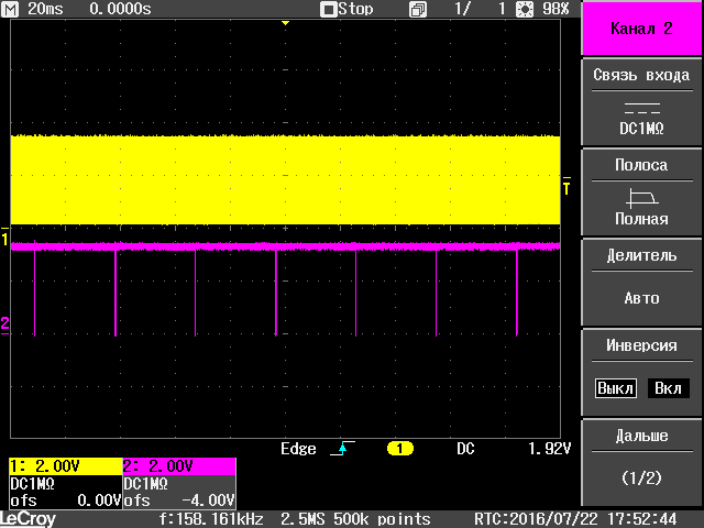
or more deployed one package:

There is no pause, the flow is continuous, the acceleration is 8 times received.
It turned out all that was planned and aspired to.
Once again the link to githab:
https://github.com/Mirn/Boot_F4_fast_uart
This is my first project on a githaba and has been published for the purpose of studying it and entering the community.
I decided to do not "hello world", but something really useful. Github is for the community and it is silly to start with a project that is useless to everyone. I remembered how my hands itched, but because of laziness they did not reach for many years. And suddenly there was a reason: because of the crisis, I will soon have just a lot of free time, but something must be done now. As a result, this turbo boot was born.
Added by:
The SFU version for STM32F7xx is made:
https://github.com/Mirn/Boot_F745_SFU
')
Source: https://habr.com/ru/post/305800/
All Articles