Learning OpenGL ES2 for Android Lesson №2. Creating triangles
Lesson number 2. Creating triangles
The basis of the code and ideas I drew from here:
1. Satia Komatineni, Dave Macklin, Saeed Hashimi. Android 3 for professionals. Creating applications for tablets and smartphones .: Trans. from English - Moscow: I.D. Williams LLC. 2012 - 1024 s.
2. http://www.learnopengles.com/android-lesson-one-getting-started/
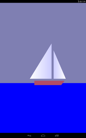
At the first lesson (you can see here https://habrahabr.ru/post/278895/ or here albatrossgames.blogspot.com/2016/03/opengl-es-2-android-1-opengl.html#more ) we are with you learned how to fill the screen with one color using OpenGL ES. It is time to draw triangles, or rather, with the help of triangles, we will draw a sailboat that will move cyclically from left to right.
')
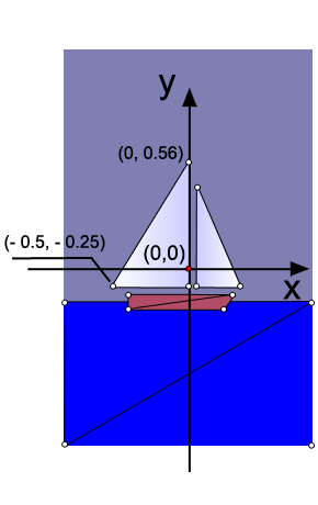
Why triangles? The fact is that in OpenGL there are only three graphic primitives: a point, a line and a triangle. The hull of the yacht (trapezium) and the sea (rectangle) are also drawn using triangles. As is known, a point in our space is determined by three coordinates (x, y, z). Since our drawing is flat, then all the points of the drawing have one coordinate along the 0z axis (it is perpendicular to the screen plane and goes towards us) will be equal to zero. For example, I indicated the coordinates on the 0x axis and 0y of the two extreme points of the large sail (grotto).
In the code, the definition of the three points of the grotto is
As you can see, a float array is created. For each point its coordinate and color scale is indicated. The first point is white, so the weights of red, green and blue are the same and equal to 1, but for the other two peaks I have changed the color for beauty. Bypassing points is done counterclockwise.
The dimension of the coordinates in OpenGL is conditional and will actually be determined by the number of pixels on the screen of the device in terms of width and height.
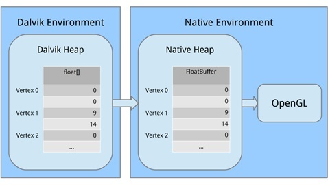
Now we need to create a buffer where we will transfer the data on points for OpenGL. This is due to the fact that OpenGL is written in a C-like language. Therefore, we translate our data into a different form that is understandable for OpenGL, allocating memory.
Let's look at each part. First, we allocated a block of computer memory using ByteBuffer.allocateDirect (); this memory will not be managed by the Garbage Collector (which is important). It is necessary to tell the method how large a block of memory should be in bytes. Since our vertices are stored in the array as float variables and occupy 4 bytes for each float, we pass in triangle1VerticesData.length * mBytesPerFloat. (Let me remind you that private final int mBytesPerFloat = 4;)
The next line tells the byte buffer how it should organize its bytes in machine code. When it comes to values that span several bytes, such as 32-bit integers, bytes can be written in a different order, for example, from the most significant value to the least significant. It is like writing a large number either from left to right or from right to left. We don't care, but what matters is that we use the same order as the system. We arrange this by calling order (ByteOrder.nativeOrder ()). Finally, it is better not to deal with individual bytes directly. We want to work with floats, so we call FloatBuffer () to get a FloatBuffer that contains the main bytes. Then we copy, starting from the zero position, the data from the Dalvik memory into the machine memory, calling mTriangle1Vertices.put (triangle1VerticesData) .position (0);
The memory will be released when the process stops, so we do not need to worry about it.
Understanding Matrices
A good lesson to understand matrices www.songho.ca/opengl/gl_transform.html
To understand the matrix, you first need to figure out how we "see" an object in OpenGL.
Imagine that you are holding a camera in your hands and want to take a picture of our sailboat.
Let our camera is in because it is called a point of view. If we do not specify a viewpoint in the code, the camera will default to the coordinates with (0,0,0).
Let's see how the camera position is defined in the code:
In the beginning, we set the background color to blue-gray, similarly, as we did in the first lesson.
Then they placed the camera, they actually indicated the coordinates of t. As you can see, the camera is shifted along the 0z axis by 1.5 units (the distance is OK).
In the following lines of code, we indicate the coordinate of the point at which the camera is looking.
The following lines of code define how the camera is oriented or the up vector position. Due to unsuccessful translations, in various articles there were inaccuracies in this matter. In our code now
This means that the camera is placed normally, so if you put it on a horizontal table and look at the sailboat in t.0.

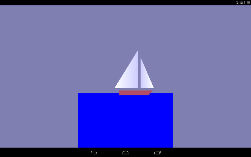
Now imagine that there are three vectors coming out of the camera, as from the so-called. Putting the final float weighting factor upY = 1.0f, we say to OpenGL that the 0U axis will be pointing upwards and see the picture, as in the beginning of the article.
But once we put these coefficients
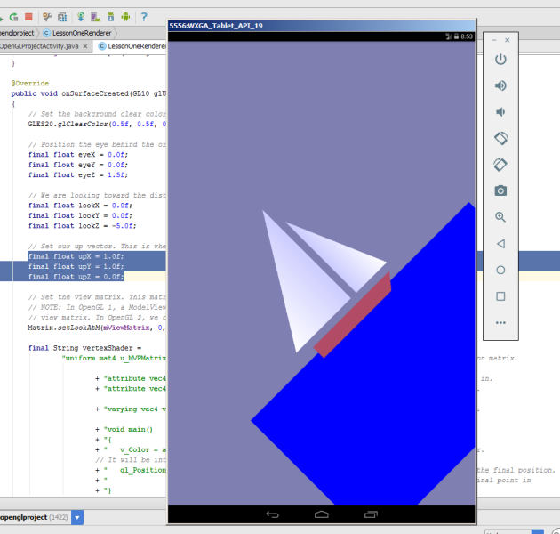
we will see the following on the emulator. Our sailboat will climb upwards.
The camera turned 45 degrees counterclockwise, if you look at the axis 0z. It is clear that if you make such a combination
the 0x camera axis will look upwards and the boat will sail vertically upwards.
We pass all our data to the setLookAtM method.
Matrix.setLookAtM (mViewMatrix, 0, eyeX, eyeY, eyeZ, lookX, lookY, lookZ, upX, upY, upZ);
Visible camera volume
Consider the following piece of code.
The onSurfaceChanged method allows you to work out the orientation change of the device itself.
Let's turn our gadget on the emulator and see this picture
Not very beautiful, but in principle what we drew.
The next line of code sets the screen size. First, set the coordinates of the lower point of the left corner of the screen (0,0), and then the width and height of the screen.
GLES20.glViewport (0, 0, width, height);
Let's review our drawing again:
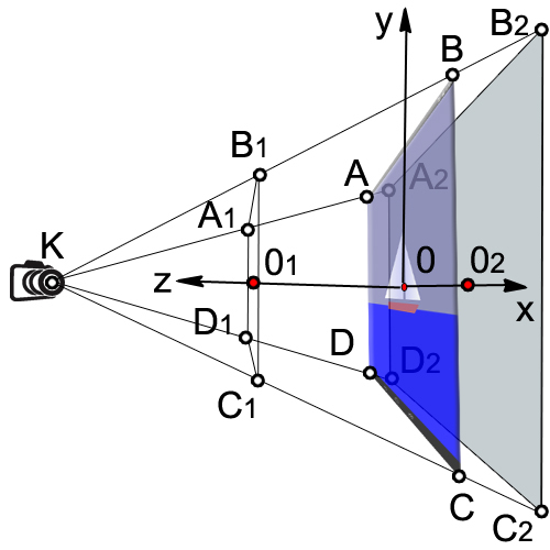
The volume that our camera sees is enclosed in the volume of a truncated pyramid (A 1 , B 1 , C 1 , D 1 , A 2 , B 2 , C 2 , D 2 ).
First we find the ratio of the width to the height of the device (ratio).
final float ratio = (float) width / height;
Then we set the coordinate to 0x of the left and right side of the visible box (A 1 , B 1 , C 1 , D 1 ).
final float left = -ratio;
final float right = ratio;
We specify the 0 coordinate of the lower and upper sides of the parallelepiped (A 1 , B 1 , C 1 , D 1 ).
final float bottom = -1.0f;
final float top = 1.0f;
The distance from the camera to the front side (KO 1 )
final float near = 1.0f;
The distance from the camera to the back side (KO 2 )
final float far = 10.0f;
Apply matrix transformation
Matrix.frustumM (mProjectionMatrix, 0, left, right, bottom, top, near, far);
There are several different types of matrices that we use:
1. Matrix model. This matrix is used to place the model somewhere in the "world." For example, if you have a car model, and you want to position it at a distance of 1000 m to the east, you will use the model matrix.
2. The matrix of the form. This matrix is a camera. If we want to look at our car, which is 1000 m to the east, we must move ourselves to 1000 m to the east. Or you can stay still and move the rest of the world 1000 meters to the west. To do this, we will use a view matrix.
3. Projection matrix. Since our screens are flat, we need to make a final transformation into the “project” of our view on the screen and get a 3D perspective. To do this, use the projection matrix.
Definition of vertex and fragment shaders
Even the simplest drawings in OpenGL ES 2.0 require the creation of software segments called shaders. Shaders form the core of OpenGL ES 2.0. Vertices are processed by vertex shaders and deal only with vertex points. The spaces between the vertices are processed using fragment shaders; they deal with each pixel on the screen.
For writing shaders use the programming language OpenGL Shading Language (GLSL).
Each shader mainly consists of input, output and program. First we define the form, which is a combined matrix containing all our transformations. It is constant for all vertices and is used to project them onto the screen. Then we define two attributes for the position and color. These attributes will be read from the buffer that we defined earlier; they set the position and color of each vertex. Then we define the variation (color change), which interpolates the values for the entire triangle and passes it to the fragment shader. When it comes to the fragment shader, it will contain an interpolated value for each pixel.
Let's say we have defined a triangle whose vertices will be red, green and blue, and its size will occupy 10 pixels on the screen. When executing a fragment shader, it will contain a different changing color for each pixel. At some point, that change will be red, but halfway between red and blue, it may be a purple color.
Consider our vertex shader
Through the uniform (uniform) external data are transferred to the shaders, which can be used for calculations. Uniforms can only be used for reading. Uniforms can be transferred to both vertex and fragment shaders. In our case, there is only one uniform - this is the matrix of the projection view-model u_MVPMatrix and it is passed to the vertex shader. The mat4 keyword means that it is a 4x4 matrix consisting of floating point numbers. Uniforms have nothing to do with a particular vertex and are global constants. For the name of the uniform usually use the prefix u_.
Attributes (attribute) is a property of the vertex. Vertices may have different attributes. For example, position coordinates in space, coordinates of the normal vector, color. In addition, you can pass any attributes to the vertex shader. It is important to understand that an attribute is a property of a vertex and therefore it must be defined for each vertex. Attributes are transmitted only to the vertex shader. Attributes are available to the vertex shader only for reading. Attributes cannot be defined in a fragment shader. In the future, for convenience, we denote attributes with the prefix a_.
Define three attributes in the vertex shader:
attribute vec4 a_Position;
The variable a_Position is a vertex attribute that deals with the position of the vertex (coordinates); it is a four-component vector (vec4).
Vertex color attribute
attribute vec4 a_Color;
Color Interpolation Attribute
varying vec4 v_Color;
Consider the main function code in more detail:
v_Color = a_Color;
We transfer the information about the color of the vertices to the fragment shader.
gl_Position = u_MVPMatrix * a_Position;
Transform the position of the vertices using the matrix and write to the new variable gl_Position.
The system variable gl_Position is a four-component vector defining the vertex coordinates projected onto the screen plane. The variable gl_Position must be defined in the vertex shader, otherwise we will not see anything on the screen.
Let us proceed to the consideration of the fragment shader.
The default accuracy is set to medium, since we do not need it high in the case of a fragment shader. In the vertex shader, the default accuracy is high.
precision mediump float;
The ultimate goal of a fragment shader is to get the color of a pixel. The calculated color of the pixel must be recorded in the system variable gl_FragColor. In our simplest example, we do not calculate the color of the pixel in the fragment shader, but simply assign the value of the color v_color, obtained by interpolation from the colors of the vertices:
gl_FragColor = v_color;
Loading shaders in OpenGL
Linking vertex and fragment shaders together in a program
Before using our vertex and fragment shaders, we need to link them together in the program. This is what connects the output of the vertex shader to the input of the fragment shader. This is also what allows us to transfer input from our program and use shaders to draw our shapes.
We create a new software object, and if it succeeds, we then attach our shaders. We want to pass position and color data as attributes, so we need to link these attributes. Then we tie the shaders together.
After we have successfully linked our program, we will finish with a couple of big tasks, now we can really use it. The first task is to get links, so we can transfer data to the program. Then we tell OpenGL to use this program when drawing occurs. Since we only use one program in this tutorial, we can put this in onSurfaceCreated () instead of onDrawFrame ().
Installing a perspective projection
Our onSurfaceChanged () method is called at least once, as well as whenever our surface changes. Since we need to reset our projection matrix whenever the projection on the screen changes, onSurfaceChanged () is the perfect place to do this.
Displaying objects on the screen
The output is produced in the onDrawFrame method (GL10 glUnused)
To make the triangles move along the 0x axis, we apply the displacement matrix and set the increase in x offset by 0.001 for each surface update. As soon as x reaches 1 or the right edge of the screen, reset it.
Matrix.translateM (mModelMatrix, 0, x + 0.3f, 0.0f, 0.0f);
drawTriangle (mTriangle2Vertices);
if (x <= 1) {x = (float) (x + 0.001);}
else {x = 0;}
I think for the second lesson is more than enough. Many questions are missed, and their understanding will come later.
Running a lesson on Android Studio.
I recommend using the draft of the previous lesson and just copying this code into it.
If you do not have it, then create a project First Open GL Project
AndroidManifest.xml
FirstOpenGLProjectActivity.java
LessonOneRenderer.java
1. , , . Android 3 . .: . from English – .: «..». 2012 – 1024 .
2. http://www.learnopengles.com/android-lesson-one-getting-started/
3. http://andmonahov.blogspot.com/2012/10/opengl-es-20-1.html
4. https://www.opengl.org/sdk/docs/tutorials/ClockworkCoders/attributes.php
5. https://www.khronos.org/opengles/sdk/docs/reference_cards/OpenGL-ES-2_0-Reference-card.pdf
The basis of the code and ideas I drew from here:
1. Satia Komatineni, Dave Macklin, Saeed Hashimi. Android 3 for professionals. Creating applications for tablets and smartphones .: Trans. from English - Moscow: I.D. Williams LLC. 2012 - 1024 s.
2. http://www.learnopengles.com/android-lesson-one-getting-started/
At the first lesson (you can see here https://habrahabr.ru/post/278895/ or here albatrossgames.blogspot.com/2016/03/opengl-es-2-android-1-opengl.html#more ) we are with you learned how to fill the screen with one color using OpenGL ES. It is time to draw triangles, or rather, with the help of triangles, we will draw a sailboat that will move cyclically from left to right.
')
Why triangles? The fact is that in OpenGL there are only three graphic primitives: a point, a line and a triangle. The hull of the yacht (trapezium) and the sea (rectangle) are also drawn using triangles. As is known, a point in our space is determined by three coordinates (x, y, z). Since our drawing is flat, then all the points of the drawing have one coordinate along the 0z axis (it is perpendicular to the screen plane and goes towards us) will be equal to zero. For example, I indicated the coordinates on the 0x axis and 0y of the two extreme points of the large sail (grotto).
In the code, the definition of the three points of the grotto is
// this triangle is white-blue. First sail is mainsail final float[] triangle1VerticesData = { // X, Y, Z, // R, G, B, A -0.5f, -0.25f, 0.0f, 1.0f, 1.0f, 1.0f, 1.0f, 0.0f, -0.25f, 0.0f, 0.8f, 0.8f, 1.0f, 1.0f, 0.0f, 0.56f, 0.0f, 0.8f, 0.8f, 1.0f, 1.0f}; As you can see, a float array is created. For each point its coordinate and color scale is indicated. The first point is white, so the weights of red, green and blue are the same and equal to 1, but for the other two peaks I have changed the color for beauty. Bypassing points is done counterclockwise.
The dimension of the coordinates in OpenGL is conditional and will actually be determined by the number of pixels on the screen of the device in terms of width and height.
Now we need to create a buffer where we will transfer the data on points for OpenGL. This is due to the fact that OpenGL is written in a C-like language. Therefore, we translate our data into a different form that is understandable for OpenGL, allocating memory.
/** How many bytes per float. */ private final int mBytesPerFloat = 4; // Initialize the buffers. mTriangle1Vertices = ByteBuffer.allocateDirect(triangle1VerticesData.length * mBytesPerFloat) .order(ByteOrder.nativeOrder()).asFloatBuffer(); mTriangle1Vertices.put(triangle1VerticesData).position(0); Let's look at each part. First, we allocated a block of computer memory using ByteBuffer.allocateDirect (); this memory will not be managed by the Garbage Collector (which is important). It is necessary to tell the method how large a block of memory should be in bytes. Since our vertices are stored in the array as float variables and occupy 4 bytes for each float, we pass in triangle1VerticesData.length * mBytesPerFloat. (Let me remind you that private final int mBytesPerFloat = 4;)
The next line tells the byte buffer how it should organize its bytes in machine code. When it comes to values that span several bytes, such as 32-bit integers, bytes can be written in a different order, for example, from the most significant value to the least significant. It is like writing a large number either from left to right or from right to left. We don't care, but what matters is that we use the same order as the system. We arrange this by calling order (ByteOrder.nativeOrder ()). Finally, it is better not to deal with individual bytes directly. We want to work with floats, so we call FloatBuffer () to get a FloatBuffer that contains the main bytes. Then we copy, starting from the zero position, the data from the Dalvik memory into the machine memory, calling mTriangle1Vertices.put (triangle1VerticesData) .position (0);
The memory will be released when the process stops, so we do not need to worry about it.
Understanding Matrices
A good lesson to understand matrices www.songho.ca/opengl/gl_transform.html
To understand the matrix, you first need to figure out how we "see" an object in OpenGL.
Imagine that you are holding a camera in your hands and want to take a picture of our sailboat.
Let our camera is in because it is called a point of view. If we do not specify a viewpoint in the code, the camera will default to the coordinates with (0,0,0).
Let's see how the camera position is defined in the code:
@Override public void onSurfaceCreated(GL10 glUnused, EGLConfig config) { // Set the background clear color to gray. GLES20.glClearColor(0.5f, 0.5f, 0.7f, 1.0f); // Position the eye behind the origin. final float eyeX = 0.0f; final float eyeY = 0.0f; final float eyeZ = 1.5f; // We are looking toward the distance final float lookX = 0.0f; final float lookY = 0.0f; final float lookZ = -5.0f; // Set our up vector. This is where our head would be pointing were we holding the camera. final float upX = 0.0f; final float upY = 1.0f; final float upZ = 0.0f; // Set the view matrix. This matrix can be said to represent the camera position. // NOTE: In OpenGL 1, a ModelView matrix is used, which is a combination of a model and // view matrix. In OpenGL 2, we can keep track of these matrices separately if we choose. Matrix.setLookAtM(mViewMatrix, 0, eyeX, eyeY, eyeZ, lookX, lookY, lookZ, upX, upY, upZ); In the beginning, we set the background color to blue-gray, similarly, as we did in the first lesson.
GLES20.glClearColor(0.5f, 0.5f, 0.7f, 1.0f); Then they placed the camera, they actually indicated the coordinates of t. As you can see, the camera is shifted along the 0z axis by 1.5 units (the distance is OK).
final float eyeX = 0.0f; final float eyeY = 0.0f; final float eyeZ = 1.5f; In the following lines of code, we indicate the coordinate of the point at which the camera is looking.
final float lookX = 0.0f; final float lookY = 0.0f; final float lookZ = -5.0f; The following lines of code define how the camera is oriented or the up vector position. Due to unsuccessful translations, in various articles there were inaccuracies in this matter. In our code now
final float upX = 0.0f; final float upY = 1.0f; final float upZ = 0.0f; This means that the camera is placed normally, so if you put it on a horizontal table and look at the sailboat in t.0.
Now imagine that there are three vectors coming out of the camera, as from the so-called. Putting the final float weighting factor upY = 1.0f, we say to OpenGL that the 0U axis will be pointing upwards and see the picture, as in the beginning of the article.
But once we put these coefficients
final float upX = 1.0f; final float upY = 1.0f; final float upZ = 0.0f; we will see the following on the emulator. Our sailboat will climb upwards.
The camera turned 45 degrees counterclockwise, if you look at the axis 0z. It is clear that if you make such a combination
final float upX = 1.0f; final float upY = 0.0f; final float upZ = 0.0f; the 0x camera axis will look upwards and the boat will sail vertically upwards.
We pass all our data to the setLookAtM method.
Matrix.setLookAtM (mViewMatrix, 0, eyeX, eyeY, eyeZ, lookX, lookY, lookZ, upX, upY, upZ);
Visible camera volume
Consider the following piece of code.
@Override public void onSurfaceChanged(GL10 glUnused, int width, int height) { // Set the OpenGL viewport to the same size as the surface. GLES20.glViewport(0, 0, width, height); // Create a new perspective projection matrix. The height will stay the same // while the width will vary as per aspect ratio. final float ratio = (float) width / height; final float left = -ratio; final float right = ratio; final float bottom = -1.0f; final float top = 1.0f; final float near = 1.0f; final float far = 10.0f; Matrix.frustumM(mProjectionMatrix, 0, left, right, bottom, top, near, far); } The onSurfaceChanged method allows you to work out the orientation change of the device itself.
Let's turn our gadget on the emulator and see this picture
Not very beautiful, but in principle what we drew.
The next line of code sets the screen size. First, set the coordinates of the lower point of the left corner of the screen (0,0), and then the width and height of the screen.
GLES20.glViewport (0, 0, width, height);
Let's review our drawing again:
The volume that our camera sees is enclosed in the volume of a truncated pyramid (A 1 , B 1 , C 1 , D 1 , A 2 , B 2 , C 2 , D 2 ).
First we find the ratio of the width to the height of the device (ratio).
final float ratio = (float) width / height;
Then we set the coordinate to 0x of the left and right side of the visible box (A 1 , B 1 , C 1 , D 1 ).
final float left = -ratio;
final float right = ratio;
We specify the 0 coordinate of the lower and upper sides of the parallelepiped (A 1 , B 1 , C 1 , D 1 ).
final float bottom = -1.0f;
final float top = 1.0f;
The distance from the camera to the front side (KO 1 )
final float near = 1.0f;
The distance from the camera to the back side (KO 2 )
final float far = 10.0f;
Apply matrix transformation
Matrix.frustumM (mProjectionMatrix, 0, left, right, bottom, top, near, far);
There are several different types of matrices that we use:
1. Matrix model. This matrix is used to place the model somewhere in the "world." For example, if you have a car model, and you want to position it at a distance of 1000 m to the east, you will use the model matrix.
2. The matrix of the form. This matrix is a camera. If we want to look at our car, which is 1000 m to the east, we must move ourselves to 1000 m to the east. Or you can stay still and move the rest of the world 1000 meters to the west. To do this, we will use a view matrix.
3. Projection matrix. Since our screens are flat, we need to make a final transformation into the “project” of our view on the screen and get a 3D perspective. To do this, use the projection matrix.
Definition of vertex and fragment shaders
Even the simplest drawings in OpenGL ES 2.0 require the creation of software segments called shaders. Shaders form the core of OpenGL ES 2.0. Vertices are processed by vertex shaders and deal only with vertex points. The spaces between the vertices are processed using fragment shaders; they deal with each pixel on the screen.
For writing shaders use the programming language OpenGL Shading Language (GLSL).
Each shader mainly consists of input, output and program. First we define the form, which is a combined matrix containing all our transformations. It is constant for all vertices and is used to project them onto the screen. Then we define two attributes for the position and color. These attributes will be read from the buffer that we defined earlier; they set the position and color of each vertex. Then we define the variation (color change), which interpolates the values for the entire triangle and passes it to the fragment shader. When it comes to the fragment shader, it will contain an interpolated value for each pixel.
Let's say we have defined a triangle whose vertices will be red, green and blue, and its size will occupy 10 pixels on the screen. When executing a fragment shader, it will contain a different changing color for each pixel. At some point, that change will be red, but halfway between red and blue, it may be a purple color.
Consider our vertex shader
final String vertexShader = "uniform mat4 u_MVPMatrix; \n" // A constant representing the combined model/view/projection matrix. + "attribute vec4 a_Position; \n" // Per-vertex position information we will pass in. + "attribute vec4 a_Color; \n" // Per-vertex color information we will pass in. + "varying vec4 v_Color; \n" // This will be passed into the fragment shader. + "void main() \n" // The entry point for our vertex shader. + "{ \n" + " v_Color = a_Color; \n" // Pass the color through to the fragment shader. // It will be interpolated across the triangle. + " gl_Position = u_MVPMatrix \n" // gl_Position is a special variable used to store the final position. + " * a_Position; \n" // Multiply the vertex by the matrix to get the final point in + "} \n"; // normalized screen coordinates. Through the uniform (uniform) external data are transferred to the shaders, which can be used for calculations. Uniforms can only be used for reading. Uniforms can be transferred to both vertex and fragment shaders. In our case, there is only one uniform - this is the matrix of the projection view-model u_MVPMatrix and it is passed to the vertex shader. The mat4 keyword means that it is a 4x4 matrix consisting of floating point numbers. Uniforms have nothing to do with a particular vertex and are global constants. For the name of the uniform usually use the prefix u_.
Attributes (attribute) is a property of the vertex. Vertices may have different attributes. For example, position coordinates in space, coordinates of the normal vector, color. In addition, you can pass any attributes to the vertex shader. It is important to understand that an attribute is a property of a vertex and therefore it must be defined for each vertex. Attributes are transmitted only to the vertex shader. Attributes are available to the vertex shader only for reading. Attributes cannot be defined in a fragment shader. In the future, for convenience, we denote attributes with the prefix a_.
Define three attributes in the vertex shader:
attribute vec4 a_Position;
The variable a_Position is a vertex attribute that deals with the position of the vertex (coordinates); it is a four-component vector (vec4).
Vertex color attribute
attribute vec4 a_Color;
Color Interpolation Attribute
varying vec4 v_Color;
Consider the main function code in more detail:
v_Color = a_Color;
We transfer the information about the color of the vertices to the fragment shader.
gl_Position = u_MVPMatrix * a_Position;
Transform the position of the vertices using the matrix and write to the new variable gl_Position.
The system variable gl_Position is a four-component vector defining the vertex coordinates projected onto the screen plane. The variable gl_Position must be defined in the vertex shader, otherwise we will not see anything on the screen.
Let us proceed to the consideration of the fragment shader.
final String fragmentShader = "precision mediump float; \n" // Set the default precision to medium. We don't need as high of a // precision in the fragment shader. + "varying vec4 v_Color; \n" // This is the color from the vertex shader interpolated across the // triangle per fragment. + "void main() \n" // The entry point for our fragment shader. + "{ \n" + " gl_FragColor = v_Color; \n" // Pass the color directly through the pipeline. + "} \n"; The default accuracy is set to medium, since we do not need it high in the case of a fragment shader. In the vertex shader, the default accuracy is high.
precision mediump float;
The ultimate goal of a fragment shader is to get the color of a pixel. The calculated color of the pixel must be recorded in the system variable gl_FragColor. In our simplest example, we do not calculate the color of the pixel in the fragment shader, but simply assign the value of the color v_color, obtained by interpolation from the colors of the vertices:
gl_FragColor = v_color;
Loading shaders in OpenGL
// Load in the vertex shader. int vertexShaderHandle = GLES20.glCreateShader(GLES20.GL_VERTEX_SHADER); if (vertexShaderHandle != 0) { // Pass in the shader source. GLES20.glShaderSource(vertexShaderHandle, vertexShader); // Compile the shader. GLES20.glCompileShader(vertexShaderHandle); // Get the compilation status. final int[] compileStatus = new int[1]; GLES20.glGetShaderiv(vertexShaderHandle, GLES20.GL_COMPILE_STATUS, compileStatus, 0); // If the compilation failed, delete the shader. if (compileStatus[0] == 0) { GLES20.glDeleteShader(vertexShaderHandle); vertexShaderHandle = 0; } } if (vertexShaderHandle == 0) { throw new RuntimeException("Error creating vertex shader."); } Linking vertex and fragment shaders together in a program
// Create a program object and store the handle to it. int programHandle = GLES20.glCreateProgram(); if (programHandle != 0) { // Bind the vertex shader to the program. GLES20.glAttachShader(programHandle, vertexShaderHandle); // Bind the fragment shader to the program. GLES20.glAttachShader(programHandle, fragmentShaderHandle); // Bind attributes GLES20.glBindAttribLocation(programHandle, 0, "a_Position"); GLES20.glBindAttribLocation(programHandle, 1, "a_Color"); // Link the two shaders together into a program. GLES20.glLinkProgram(programHandle); // Get the link status. final int[] linkStatus = new int[1]; GLES20.glGetProgramiv(programHandle, GLES20.GL_LINK_STATUS, linkStatus, 0); // If the link failed, delete the program. if (linkStatus[0] == 0) { GLES20.glDeleteProgram(programHandle); programHandle = 0; } } if (programHandle == 0) { throw new RuntimeException("Error creating program."); } Before using our vertex and fragment shaders, we need to link them together in the program. This is what connects the output of the vertex shader to the input of the fragment shader. This is also what allows us to transfer input from our program and use shaders to draw our shapes.
We create a new software object, and if it succeeds, we then attach our shaders. We want to pass position and color data as attributes, so we need to link these attributes. Then we tie the shaders together.
//New class members /** This will be used to pass in the transformation matrix. */ private int mMVPMatrixHandle; /** This will be used to pass in model position information. */ private int mPositionHandle; /** This will be used to pass in model color information. */ private int mColorHandle; @Override public void onSurfaceCreated(GL10 glUnused, EGLConfig config) { ... // Set program handles. These will later be used to pass in values to the program. mMVPMatrixHandle = GLES20.glGetUniformLocation(programHandle, "u_MVPMatrix"); mPositionHandle = GLES20.glGetAttribLocation(programHandle, "a_Position"); mColorHandle = GLES20.glGetAttribLocation(programHandle, "a_Color"); // Tell OpenGL to use this program when rendering. GLES20.glUseProgram(programHandle); } After we have successfully linked our program, we will finish with a couple of big tasks, now we can really use it. The first task is to get links, so we can transfer data to the program. Then we tell OpenGL to use this program when drawing occurs. Since we only use one program in this tutorial, we can put this in onSurfaceCreated () instead of onDrawFrame ().
Installing a perspective projection
// New class members /** Store the projection matrix. This is used to project the scene onto a 2D viewport. */ private float[] mProjectionMatrix = new float[16]; @Override public void onSurfaceChanged(GL10 glUnused, int width, int height) { // Set the OpenGL viewport to the same size as the surface. GLES20.glViewport(0, 0, width, height); // Create a new perspective projection matrix. The height will stay the same // while the width will vary as per aspect ratio. final float ratio = (float) width / height; final float left = -ratio; final float right = ratio; final float bottom = -1.0f; final float top = 1.0f; final float near = 1.0f; final float far = 10.0f; Matrix.frustumM(mProjectionMatrix, 0, left, right, bottom, top, near, far); } Our onSurfaceChanged () method is called at least once, as well as whenever our surface changes. Since we need to reset our projection matrix whenever the projection on the screen changes, onSurfaceChanged () is the perfect place to do this.
Displaying objects on the screen
The output is produced in the onDrawFrame method (GL10 glUnused)
To make the triangles move along the 0x axis, we apply the displacement matrix and set the increase in x offset by 0.001 for each surface update. As soon as x reaches 1 or the right edge of the screen, reset it.
Matrix.translateM (mModelMatrix, 0, x + 0.3f, 0.0f, 0.0f);
drawTriangle (mTriangle2Vertices);
if (x <= 1) {x = (float) (x + 0.001);}
else {x = 0;}
I think for the second lesson is more than enough. Many questions are missed, and their understanding will come later.
Running a lesson on Android Studio.
I recommend using the draft of the previous lesson and just copying this code into it.
If you do not have it, then create a project First Open GL Project
AndroidManifest.xml
<?xml version="1.0" encoding="utf-8"?> <manifest xmlns:android="http://schemas.android.com/apk/res/android" package="com.adc2017gmail.firstopenglproject"> <application android:allowBackup="true" android:icon="@mipmap/ic_launcher" android:label="@string/app_name" android:supportsRtl="true" android:theme="@style/AppTheme"> <uses-feature android:glEsVersion="0x00020000" android:required="true" /> <activity android:name=".FirstOpenGLProjectActivity"> <intent-filter> <action android:name="android.intent.action.MAIN" /> <category android:name="android.intent.category.LAUNCHER" /> </intent-filter> </activity> </application> </manifest> FirstOpenGLProjectActivity.java
package com.adc2017gmail.firstopenglproject; import android.app.Activity; import android.app.ActivityManager; import android.content.Context; import android.content.pm.ConfigurationInfo; import android.opengl.GLSurfaceView; import android.os.Bundle; public class FirstOpenGLProjectActivity extends Activity { /** Hold a reference to our GLSurfaceView */ private GLSurfaceView mGLSurfaceView; @Override public void onCreate(Bundle savedInstanceState) { super.onCreate(savedInstanceState); mGLSurfaceView = new GLSurfaceView(this); // Check if the system supports OpenGL ES 2.0. final ActivityManager activityManager = (ActivityManager) getSystemService(Context.ACTIVITY_SERVICE); final ConfigurationInfo configurationInfo = activityManager.getDeviceConfigurationInfo(); final boolean supportsEs2 = configurationInfo.reqGlEsVersion >= 0x20000; if (supportsEs2) { // Request an OpenGL ES 2.0 compatible context. mGLSurfaceView.setEGLContextClientVersion(2); // Set the renderer to our demo renderer, defined below. mGLSurfaceView.setRenderer(new LessonOneRenderer()); } else { // This is where you could create an OpenGL ES 1.x compatible // renderer if you wanted to support both ES 1 and ES 2. return; } setContentView(mGLSurfaceView); } @Override protected void onResume() { // The activity must call the GL surface view's onResume() on activity onResume(). super.onResume(); mGLSurfaceView.onResume(); } @Override protected void onPause() { // The activity must call the GL surface view's onPause() on activity onPause(). super.onPause(); mGLSurfaceView.onPause(); } } LessonOneRenderer.java
package com.adc2017gmail.firstopenglproject; import android.opengl.GLES20; import android.opengl.GLSurfaceView; import android.opengl.Matrix; import java.nio.ByteBuffer; import java.nio.ByteOrder; import java.nio.FloatBuffer; import javax.microedition.khronos.egl.EGLConfig; import javax.microedition.khronos.opengles.GL10; /** * This class implements our custom renderer. Note that the GL10 parameter passed in is unused for OpenGL ES 2.0 * renderers -- the static class GLES20 is used instead. */ public class LessonOneRenderer implements GLSurfaceView.Renderer { /** * Store the model matrix. This matrix is used to move models from object space (where each model can be thought * of being located at the center of the universe) to world space. */ private float[] mModelMatrix = new float[16]; /** * Store the view matrix. This can be thought of as our camera. This matrix transforms world space to eye space; * it positions things relative to our eye. */ private float[] mViewMatrix = new float[16]; /** Store the projection matrix. This is used to project the scene onto a 2D viewport. */ private float[] mProjectionMatrix = new float[16]; /** Allocate storage for the final combined matrix. This will be passed into the shader program. */ private float[] mMVPMatrix = new float[16]; /** Store our model data in a float buffer. */ private final FloatBuffer mTriangle1Vertices; private final FloatBuffer mTriangle2Vertices; private final FloatBuffer mTriangle3Vertices; private final FloatBuffer mTriangle4Vertices; private final FloatBuffer mTriangle5Vertices; private final FloatBuffer mTriangle6Vertices; /** This will be used to pass in the transformation matrix. */ private int mMVPMatrixHandle; /** This will be used to pass in model position information. */ private int mPositionHandle; /** This will be used to pass in model color information. */ private int mColorHandle; /** How many bytes per float. */ private final int mBytesPerFloat = 4; /** How many elements per vertex. */ private final int mStrideBytes = 7 * mBytesPerFloat; /** Offset of the position data. */ private final int mPositionOffset = 0; /** Size of the position data in elements. */ private final int mPositionDataSize = 3; /** Offset of the color data. */ private final int mColorOffset = 3; /** Size of the color data in elements. */ private final int mColorDataSize = 4; private float x; /** * Initialize the model data. */ public LessonOneRenderer() { // Define points for equilateral triangles. // This triangle is white_blue.First sail is mainsail final float[] triangle1VerticesData = { // X, Y, Z, // R, G, B, A -0.5f, -0.25f, 0.0f, 1.0f, 1.0f, 1.0f, 1.0f, 0.0f, -0.25f, 0.0f, 0.8f, 0.8f, 1.0f, 1.0f, 0.0f, 0.56f, 0.0f, 0.8f, 0.8f, 1.0f, 1.0f}; // This triangle is white_blue..The second is called the jib sail final float[] triangle2VerticesData = { // X, Y, Z, // R, G, B, A -0.25f, -0.25f, 0.0f, 0.8f, 0.8f, 1.0f, 1.0f, 0.03f, -0.25f, 0.0f, 1.0f, 1.0f, 1.0f, 1.0f, -0.25f, 0.4f, 0.0f, 0.8f, 0.8f, 1.0f, 1.0f}; // This triangle3 is blue. final float[] triangle3VerticesData = { // X, Y, Z, // R, G, B, A -1.0f, -1.5f, 0.0f, 0.0f, 0.0f, 1.0f, 1.0f, 1.0f, -0.35f, 0.0f, 0.0f, 0.0f, 1.0f, 1.0f, -1.0f, -0.35f, 0.0f, 0.0f, 0.0f, 1.0f, 1.0f}; // This triangle4 is blue. final float[] triangle4VerticesData = { // X, Y, Z, // R, G, B, A -1.0f, -1.5f, 0.0f, 0.0f, 0.0f, 1.0f, 1.0f, 1.0f, -1.5f, 0.0f, 0.0f, 0.0f, 1.0f, 1.0f, 1.0f, -0.35f, 0.0f, 0.0f, 0.0f, 1.0f, 1.0f}; // This triangle5 is brown. final float[] triangle5VerticesData = { // X, Y, Z, // R, G, B, A -0.4f, -0.3f, 0.0f, 0.7f, 0.3f, 0.4f, 1.0f, -0.4f, -0.4f, 0.0f, 0.7f, 0.3f, 0.4f, 1.0f, 0.3f, -0.3f, 0.0f, 0.7f, 0.3f, 0.4f, 1.0f}; // This triangle6 is brown. final float[] triangle6VerticesData = { // X, Y, Z, // R, G, B, A -0.4f, -0.4f, 0.0f, 0.7f, 0.3f, 0.4f, 1.0f, 0.22f, -0.4f, 0.0f, 0.7f, 0.3f, 0.4f, 1.0f, 0.3f, -0.3f, 0.0f, 0.7f, 0.3f, 0.4f, 1.0f}; // Initialize the buffers. mTriangle1Vertices = ByteBuffer.allocateDirect(triangle1VerticesData.length * mBytesPerFloat) .order(ByteOrder.nativeOrder()).asFloatBuffer(); mTriangle2Vertices = ByteBuffer.allocateDirect(triangle2VerticesData.length * mBytesPerFloat) .order(ByteOrder.nativeOrder()).asFloatBuffer(); mTriangle3Vertices = ByteBuffer.allocateDirect(triangle3VerticesData.length * mBytesPerFloat) .order(ByteOrder.nativeOrder()).asFloatBuffer(); mTriangle4Vertices = ByteBuffer.allocateDirect(triangle4VerticesData.length * mBytesPerFloat) .order(ByteOrder.nativeOrder()).asFloatBuffer(); mTriangle5Vertices = ByteBuffer.allocateDirect(triangle5VerticesData.length * mBytesPerFloat) .order(ByteOrder.nativeOrder()).asFloatBuffer(); mTriangle6Vertices = ByteBuffer.allocateDirect(triangle6VerticesData.length * mBytesPerFloat) .order(ByteOrder.nativeOrder()).asFloatBuffer(); mTriangle1Vertices.put(triangle1VerticesData).position(0); mTriangle2Vertices.put(triangle2VerticesData).position(0); mTriangle3Vertices.put(triangle3VerticesData).position(0); mTriangle4Vertices.put(triangle4VerticesData).position(0); mTriangle5Vertices.put(triangle5VerticesData).position(0); mTriangle6Vertices.put(triangle6VerticesData).position(0); } @Override public void onSurfaceCreated(GL10 glUnused, EGLConfig config) { // Set the background clear color to gray. GLES20.glClearColor(0.5f, 0.5f, 0.7f, 1.0f); // Position the eye behind the origin. final float eyeX = 0.0f; final float eyeY = 0.0f; final float eyeZ = 1.5f; // We are looking toward the distance final float lookX = 0.0f; final float lookY = 0.0f; final float lookZ = -5.0f; // Set our up vector. This is where our head would be pointing were we holding the camera. final float upX = 0.0f; final float upY = 1.0f; final float upZ = 0.0f; // Set the view matrix. This matrix can be said to represent the camera position. // NOTE: In OpenGL 1, a ModelView matrix is used, which is a combination of a model and // view matrix. In OpenGL 2, we can keep track of these matrices separately if we choose. Matrix.setLookAtM(mViewMatrix, 0, eyeX, eyeY, eyeZ, lookX, lookY, lookZ, upX, upY, upZ); final String vertexShader = "uniform mat4 u_MVPMatrix; \n" // A constant representing the combined model/view/projection matrix. + "attribute vec4 a_Position; \n" // Per-vertex position information we will pass in. + "attribute vec4 a_Color; \n" // Per-vertex color information we will pass in. + "varying vec4 v_Color; \n" // This will be passed into the fragment shader. + "void main() \n" // The entry point for our vertex shader. + "{ \n" + " v_Color = a_Color; \n" // Pass the color through to the fragment shader. // It will be interpolated across the triangle. + " gl_Position = u_MVPMatrix \n" // gl_Position is a special variable used to store the final position. + " * a_Position; \n" // Multiply the vertex by the matrix to get the final point in + "} \n"; // normalized screen coordinates. final String fragmentShader = "precision mediump float; \n" // Set the default precision to medium. We don't need as high of a // precision in the fragment shader. + "varying vec4 v_Color; \n" // This is the color from the vertex shader interpolated across the // triangle per fragment. + "void main() \n" // The entry point for our fragment shader. + "{ \n" + " gl_FragColor = v_Color; \n" // Pass the color directly through the pipeline. + "} \n"; // Load in the vertex shader. int vertexShaderHandle = GLES20.glCreateShader(GLES20.GL_VERTEX_SHADER); if (vertexShaderHandle != 0) { // Pass in the shader source. GLES20.glShaderSource(vertexShaderHandle, vertexShader); // Compile the shader. GLES20.glCompileShader(vertexShaderHandle); // Get the compilation status. final int[] compileStatus = new int[1]; GLES20.glGetShaderiv(vertexShaderHandle, GLES20.GL_COMPILE_STATUS, compileStatus, 0); // If the compilation failed, delete the shader. if (compileStatus[0] == 0) { GLES20.glDeleteShader(vertexShaderHandle); vertexShaderHandle = 0; } } if (vertexShaderHandle == 0) { throw new RuntimeException("Error creating vertex shader."); } // Load in the fragment shader shader. int fragmentShaderHandle = GLES20.glCreateShader(GLES20.GL_FRAGMENT_SHADER); if (fragmentShaderHandle != 0) { // Pass in the shader source. GLES20.glShaderSource(fragmentShaderHandle, fragmentShader); // Compile the shader. GLES20.glCompileShader(fragmentShaderHandle); // Get the compilation status. final int[] compileStatus = new int[1]; GLES20.glGetShaderiv(fragmentShaderHandle, GLES20.GL_COMPILE_STATUS, compileStatus, 0); // If the compilation failed, delete the shader. if (compileStatus[0] == 0) { GLES20.glDeleteShader(fragmentShaderHandle); fragmentShaderHandle = 0; } } if (fragmentShaderHandle == 0) { throw new RuntimeException("Error creating fragment shader."); } // Create a program object and store the handle to it. int programHandle = GLES20.glCreateProgram(); if (programHandle != 0) { // Bind the vertex shader to the program. GLES20.glAttachShader(programHandle, vertexShaderHandle); // Bind the fragment shader to the program. GLES20.glAttachShader(programHandle, fragmentShaderHandle); // Bind attributes GLES20.glBindAttribLocation(programHandle, 0, "a_Position"); GLES20.glBindAttribLocation(programHandle, 1, "a_Color"); // Link the two shaders together into a program. GLES20.glLinkProgram(programHandle); // Get the link status. final int[] linkStatus = new int[1]; GLES20.glGetProgramiv(programHandle, GLES20.GL_LINK_STATUS, linkStatus, 0); // If the link failed, delete the program. if (linkStatus[0] == 0) { GLES20.glDeleteProgram(programHandle); programHandle = 0; } } if (programHandle == 0) { throw new RuntimeException("Error creating program."); } // Set program handles. These will later be used to pass in values to the program. mMVPMatrixHandle = GLES20.glGetUniformLocation(programHandle, "u_MVPMatrix"); mPositionHandle = GLES20.glGetAttribLocation(programHandle, "a_Position"); mColorHandle = GLES20.glGetAttribLocation(programHandle, "a_Color"); // Tell OpenGL to use this program when rendering. GLES20.glUseProgram(programHandle); } @Override public void onSurfaceChanged(GL10 glUnused, int width, int height) { // Set the OpenGL viewport to the same size as the surface. GLES20.glViewport(0, 0, width, height); // Create a new perspective projection matrix. The height will stay the same // while the width will vary as per aspect ratio. final float ratio = (float) width / height; final float left = -ratio; final float right = ratio; final float bottom = -1.0f; final float top = 1.0f; final float near = 1.0f; final float far = 10.0f; Matrix.frustumM(mProjectionMatrix, 0, left, right, bottom, top, near, far); } @Override public void onDrawFrame(GL10 glUnused) { GLES20.glClear(GLES20.GL_DEPTH_BUFFER_BIT | GLES20.GL_COLOR_BUFFER_BIT); // Draw the triangle facing straight on. Matrix.setIdentityM(mModelMatrix, 0); Matrix.translateM(mModelMatrix, 0, x, 0.0f, 0.0f); drawTriangle(mTriangle1Vertices); // Draw triangle_2. Matrix.setIdentityM(mModelMatrix, 0); Matrix.translateM(mModelMatrix, 0, x + 0.3f, 0.0f, 0.0f); drawTriangle(mTriangle2Vertices); if(x<=1){x = (float) (x + 0.001);} else {x=0;} // Draw triangle_3. Matrix.setIdentityM(mModelMatrix, 0); drawTriangle(mTriangle3Vertices); // Draw triangle_4. Matrix.setIdentityM(mModelMatrix, 0); drawTriangle(mTriangle4Vertices); // Draw triangle_5. Boat Matrix.setIdentityM(mModelMatrix, 0); Matrix.translateM(mModelMatrix, 0, x, 0.0f, 0.0f); //Matrix.rotateM(mModelMatrix, 0, 0, 0.0f, 0.0f, 1.0f); drawTriangle(mTriangle5Vertices); // Draw triangle_6. Boat Matrix.setIdentityM(mModelMatrix, 0); Matrix.translateM(mModelMatrix, 0, x, 0.0f, 0.0f); //Matrix.rotateM(mModelMatrix, 0, 0, 0.0f, 0.0f, 1.0f); drawTriangle(mTriangle6Vertices); } /** * Draws a triangle from the given vertex data. * * @param aTriangleBuffer The buffer containing the vertex data. */ private void drawTriangle(final FloatBuffer aTriangleBuffer) { // Pass in the position information aTriangleBuffer.position(mPositionOffset); GLES20.glVertexAttribPointer(mPositionHandle, mPositionDataSize, GLES20.GL_FLOAT, false, mStrideBytes, aTriangleBuffer); GLES20.glEnableVertexAttribArray(mPositionHandle); // Pass in the color information aTriangleBuffer.position(mColorOffset); GLES20.glVertexAttribPointer(mColorHandle, mColorDataSize, GLES20.GL_FLOAT, false, mStrideBytes, aTriangleBuffer); GLES20.glEnableVertexAttribArray(mColorHandle); // This multiplies the view matrix by the model matrix, and stores the result in the MVP matrix // (which currently contains model * view). Matrix.multiplyMM(mMVPMatrix, 0, mViewMatrix, 0, mModelMatrix, 0); // This multiplies the modelview matrix by the projection matrix, and stores the result in the MVP matrix // (which now contains model * view * projection). Matrix.multiplyMM(mMVPMatrix, 0, mProjectionMatrix, 0, mMVPMatrix, 0); GLES20.glUniformMatrix4fv(mMVPMatrixHandle, 1, false, mMVPMatrix, 0); GLES20.glDrawArrays(GLES20.GL_TRIANGLES, 0, 3); } } List of sources
1. , , . Android 3 . .: . from English – .: «..». 2012 – 1024 .
2. http://www.learnopengles.com/android-lesson-one-getting-started/
3. http://andmonahov.blogspot.com/2012/10/opengl-es-20-1.html
4. https://www.opengl.org/sdk/docs/tutorials/ClockworkCoders/attributes.php
5. https://www.khronos.org/opengles/sdk/docs/reference_cards/OpenGL-ES-2_0-Reference-card.pdf
Source: https://habr.com/ru/post/305796/
All Articles