Vectorization of coordinate transformation code in space on Intel® Xeon Phi ™ using low-level instructions
Introduction
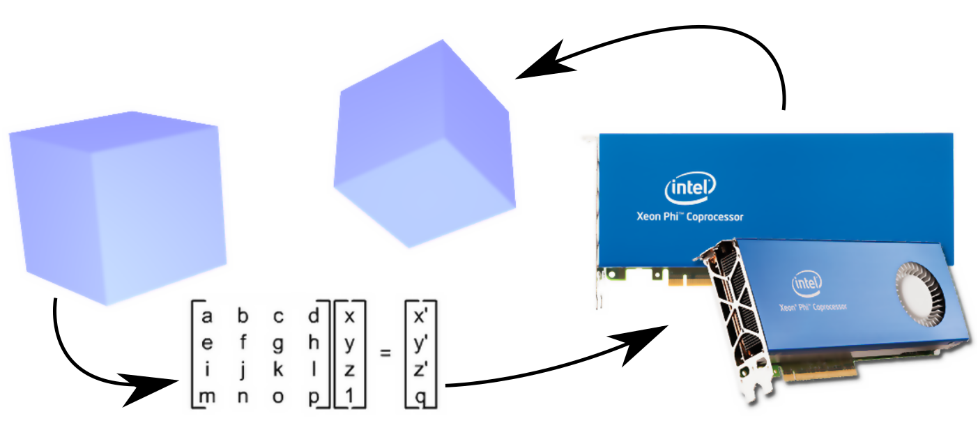
When solving problems of modeling the motion of objects in three-dimensional space, it is almost always necessary to use operations of spatial transformation associated with the multiplication of transformation matrices and vectors. For the N-body problem, this operation is used repeatedly to specify the rotation and displacement of the body relative to the origin. The matrix of spatial transformation has a dimension of 4x4, and the dimension of the vector to which the transformation is applied, respectively 4x1. Consider optimizing the performance of such an operation with a large number of matrices and vectors under the architecture of Intel® Xeon Phi ™.
The Intel® Xeon Phi ™ coprocessor has a block of 32 registers 512 bits long ( zmm00-zmm31 ). Accordingly, the C ++ compiler from Intel [1] supports a set of vector instructions that work with these registers, falling under the specification code-named KNC [2] (not to be confused with AVX-512). This set of instructions is limited compared to the instructions of the AVX-512, but nonetheless includes the operations necessary to solve the problem in question. The high-level wrappers over the machine instructions supported by the compiler are called intrinsics functions and are described in Intel’s Intel® Intrinsic Guide [3]. When registering data correctly, vector registers allow you to perform some operation directly on a data set (SIMD). Next, we will use the names for the register variables in the code that correspond to the names of the registers ( zmm00-zmm31 ) and assume that they are mapped to the same registers when compiled.
Two operations are common in spatial transformations: matrix multiplication by a transformation matrix and matrix multiplication by a vector. The operation of multiplication of transformation matrices in most cases can be reduced to a sequence of optimized operations of matrix multiplication by column vectors of another matrix, therefore the multiplication operation by vector is the most interesting, and matrix multiplication will not be considered separately. To understand how vectorization works, consider the simplest example of multiplying a 4x4 matrix by a 4x1 vector.
In this case, the following occurs:
where for clarity, an empty circle shows the elementwise multiplication of vectors.
If we place in the registers the columns of the matrix and multiply the registers of the elements of the vector, the operation can be described using intrinsic functions for multiplication and FMA (fused multiply-add - mixed multiplication with addition). That is, to obtain the result vector in the zmm00 vector register, you must load the matrix columns into the zmm00-zmm03 , multiply the elements of the vector into the zmm04-zmm07 , so that each element of the vector zmm04-zmm07 many times and then perform 3 operations:
zmm00=_mm512_mul_ps(zmm00, zmm04); zmm00=_mm512_fmadd_ps(zmm01, zmm05, zmm00); zmm00=_mm512_fmadd_ps(zmm02, zmm06, zmm00); zmm00=_mm512_fmadd_ps(zmm03, zmm07, zmm00); To arrange the columns of matrices in registers, you can use transposition, if the matrix is stored in rows, but this is a time-consuming operation, so it is best to store matrices in columns. And combine the transformations so that the matrices are obtained in columns.
In this example, with real 32-bit numbers (ps suffix), registers are used only by a quarter, since the 512-bit register fits 16 elements, and in our case only 4, that is, there is a loss 4 times. If you use double precision (equivalent code with pd suffix), then the registers will be half filled. Even such options of partial filling of registers can give acceleration if you use 4 elements from a vector register with the result for saving, since 4 operations are performed at once, instead of one.
Features of loading and unloading data
To improve the efficiency of loading data from memory into registers and unloading from registers into memory, the memory allocated in the program should be aligned along the 64-byte boundary. In this case, you can use the _mm512_load and _mm512_store with appropriate suffixes for data types.
For dynamic allocation of aligned memory, the compiler implements a special function _mm_malloc , which is used in conjunction with _mm_free . The difference from the usual function malloc that the second argument is added - the multiplicity of the alignment of the memory; for 512-bit registers, a pointer to the memory must be returned with an address multiple of 64 bytes. For Type, the syntax for aligned memory is as follows:
Type* pointer = (Type*)_mm_malloc(sizeof(Type)*N, 64); For static data arrays, memory alignment directives are also provided, for example, the following syntax is provided for defining an aligned array in the Intel compiler:
__declspec(align(64)) Type mem[N]; You can also use the supported * nix - option:
Type mem[N] __attribute__((aligned(64))); If it is impossible to level the memory, it is necessary to use intrinsiki for working with unaligned memory _mm512_loadu and _mm512_storeu . For unknown reasons, the compiler does not implement the functions of loading into registers from unaligned memory and unloading from registers to unaligned memory for KNC, for AVX-512 there are such functions.
For KNC, these functions can be implemented independently on the basis of intrinsics for partial loading to the alignment boundary:
inline __m512d _mm512_loadu_pd(const double* a) { __m512d reg = _mm512_setzero_pd(); reg =_mm512_loadunpacklo_pd(reg, a); reg =_mm512_loadunpackhi_pd(reg, a+8); return reg; } Similarly, the upload function looks like:
inline void _mm512_storeu_pd(double* a, __m512d reg) { reg =_mm512_packstorelo_pd(a, reg); reg =_mm512_packstorehi_pd(a+8,reg); return reg; } Proper use of aligned memory can lead to acceleration up to 3 times, so we will continue to consider only work with aligned memory.
Optimization with special storage of matrices in memory
In the most general case for single precision numbers, it can be noted that the matrices are loaded completely into one register. If the matrix elements are stored sequentially, then when loading we get a register with 16 elements of the same matrix. This is good for vector multiplication operations, but bad for addition, because it is necessary to add elements within a register. The operations of adding elements within a register are associated with slow instructions for mixing, shifting, and rearranging elements, or reducing, since there are no horizontal addition operations in the KNC instruction set. If you write a complex algorithm that does it in intrinsiki, you get a slower code than the one generated by the compiler optimizer.
To minimize the number of instructions, we need to make the calculations as follows:
In order to calculate 4 result vectors at once, it makes sense to arrange the data in memory so that the rows of the matrix lie alternately, and for one set of instructions, 4 matrices are multiplied by 4 vectors at once. To do this, you need to write down new matrix elements in the following order:
This shows that it is necessary to store first the first columns, then the second, then the third, and at the end the fourth immediately for 4 matrices. In one operation, 16 elements will be placed in the register:
By analogy of the vector should also be arranged on the first, second, third and fourth elements at once 4 vectors. But, as a rule, this is inconvenient, since vectors are always used as sequences of elements for addition, determining the position of bodies in space, while rotation matrices are usually calculated from trigonometric transformations, and the body orientation is given by a system of angles (for example, Euler angles) or quaternions. That is, in the computational code vector should be stored sequentially for quick access to them. Matrices can be stored arbitrarily, since they are calculated through parameters that describe the orientation, and we just vectorize the only operation we need with them in a special way, taking into account this special storage.
Based on the sequential storage of vectors, we consider how we can obtain the necessary sequences of elements. That is, if we had a vector in mind
then you need to get the next set of registers
Using the instruction of reproduction of elements, we can load elements a 1 , b 1 , c 1 , d 1 into 4 registers:
zmm08 = _mm512_extload_ps(vec + 0, _MM_UPCONV_PS_NONE, _MM_BROADCAST_1X16, _MM_HINT_NONE); zmm09 = _mm512_extload_ps(vec + 4, _MM_UPCONV_PS_NONE, _MM_BROADCAST_1X16, _MM_HINT_NONE); zmm10 = _mm512_extload_ps(vec + 8, _MM_UPCONV_PS_NONE, _MM_BROADCAST_1X16, _MM_HINT_NONE); zmm11 = _mm512_extload_ps(vec + 12, _MM_UPCONV_PS_NONE, _MM_BROADCAST_1X16, _MM_HINT_NONE); After this, it is possible to mix them in the manner necessary for us with the help of bitmasks:
zmm06 = _mm512_mask_blend_ps(mask32_0, zmm08, zmm09); zmm07 = _mm512_mask_blend_ps(mask32_1, zmm10, zmm11); zmm04 = _mm512_mask_blend_ps(mask32_2, zmm06, zmm07); For clarity, the figure shows how the loading and mixing elements in the registers.

You can mix only 2 registers, so the operation is repeated 3 times with a different mask value. After that we have the necessary content in the register zmm04 . Similar operations of loading-mixing allow to obtain the necessary elements of the vectors in the registers zmm05-zmm07 , after which you can perform multiplication and addition operations to obtain the result. This method can be applied to processors with support for instructions AVX-512 and KNC.
You may notice that the elements of the vectors must be partially duplicated by the fours in the corresponding quarters of the registers. To do this, the KNC instruction set for Intel® Xeon Phi ™ has a special swizzle operation that allows you to rearrange and replicate elements in quarters of registers. In the case of loading 4 vectors with successive elements following, the following code converts it into the necessary factors:
zmm04 = _mm512_swizzle_ps(zmm08, _MM_SWIZ_REG_AAAA); zmm05 = _mm512_swizzle_ps(zmm08, _MM_SWIZ_REG_BBBB); zmm06 = _mm512_swizzle_ps(zmm08, _MM_SWIZ_REG_CCCC); zmm07 = _mm512_swizzle_ps(zmm08, _MM_SWIZ_REG_DDDD); How the swizzle works is shown.

If we had in the register zmm08 vector of consecutive elements vec, then as a result of the work of these instructions, we will need zmm04-zmm07 . The latter option contains significantly fewer instructions, but is not applicable to the AVX-512 instruction set, so you should select the most appropriate instructions for your particular architecture and use them.
To demonstrate the advantage of the execution time obtained as a result of code optimization, we tested multiplications of a large number of transformation matrices for vectors filled with random numbers. For comparison, a multiplication test of 300,000 transformation matrices was used on the Intel® Xeon Phi ™ 5120D coprocessor.
Comparison of optimization results was carried out after a preliminary run of the same code. After warming up, the average time was selected from 10 subsequent launches. To avoid optimization of unused code, an artificial data dependency was also created (the results of the operation were recorded in a vector factor for the next operation). The results for 32 and 64-bit real numbers are shown in Table 1, where the auto-vectorization result is in the auto column.
Table 1 - Time Measurements and Optimized Code Acceleration
| type of | time with car | time with a blend | time with swizzle | acceleration blend | speeding up swizzle |
|---|---|---|---|---|---|
| 32 | 1.15 | 0.34 | 0.2 | 3.38 | 5.75 |
| 64 | 1.41 | 0.55 | 0.45 | 2.56 | 3.13 |
Optimization with ordinary storage matrices
In some cases, the matrix can not be reordered, so you need to do their loading in a special way. Consider the matrix transformation algorithm for double precision (for a single one, everything is similar, but very cumbersome). In the case of double precision, we need to place 2 sets of 4 elements in each multiplied register with matrix elements. In the KNC instruction set, there is a right-to-right gluing operation, which combines 2 registers into a sequence of 1024 bits, then shifts it by a specified number of elements to the right and writes the lower 512 bits into the resulting register. The operation is presented only for the integer data type, although in the AVX-512 instructions it is also present for real data, but due to the same bit representation, the data type is not important to us. It is necessary to bear in mind only that the number of shifted elements must be 2 times larger for double precision numbers. The path has two matrices that are stored as a sequence of columns:
To begin with, we load matrices that are stored in columns sequentially:
__m512i izmm10 = _mm512_load_epi64(pmtx); //A2-A1 __m512i izmm11 = _mm512_load_epi64(pmtx+8); //A4-A3 __m512i izmm12 = _mm512_load_epi64(pmtx+16); //B2-B1 __m512i izmm13 = _mm512_load_epi64(pmtx+24); //B4-B3 As a result of the operation in izmm10-izmm11 - the first matrix, in izmm12-izmm13 - the second. We need to place the first rows of both matrices in the zmm00 register, the second in zmm01 , the third in zmm02 , the fourth in zmm03 . For this we use gluing with a shift of 256 bits (8 integers or 4 real double precision numbers):
izmm14 = _mm512_alignr_epi32(izmm10, izmm12, 8); //A1-B2 zmm00 = (__m512d)_mm512_alignr_epi32(izmm12, izmm14, 8); //B1-A1 zmm01 = (__m512d)_mm512_alignr_epi32(izmm14, izmm10, 8); //B2-A2 izmm14 = _mm512_alignr_epi32(izmm11, izmm13, 8); //A3-B4 zmm02 = (__m512d)_mm512_alignr_epi32(izmm13, izmm14, 8); //B3-A3 zmm03 = (__m512d)_mm512_alignr_epi32(izmm14, izmm11, 8); //B4-A4 The picture shows how it works.

As a result of the operation in the registers zmm00-zmm03 we obtain the required sequence of matrix columns. After that, using the swizzle to load vectors into the zmm04-zmm07 and the subsequent use of FMA instructions, as was done earlier, allows to obtain the result for two operations of multiplying the transformation matrices by two vectors in the zmm00 register.
zmm04 = _mm512_swizzle_pd(zmm08, _MM_SWIZ_REG_AAAA); zmm05 = _mm512_swizzle_pd(zmm08, _MM_SWIZ_REG_BBBB); zmm06 = _mm512_swizzle_pd(zmm08, _MM_SWIZ_REG_CCCC); zmm07 = _mm512_swizzle_pd(zmm08, _MM_SWIZ_REG_DDDD); zmm00=_mm512_mul_pd(zmm00, zmm04); zmm00=_mm512_fmadd_pd(zmm01, zmm05, zmm00); zmm00=_mm512_fmadd_pd(zmm02, zmm06, zmm00); zmm00=_mm512_fmadd_pd(zmm03, zmm07, zmm00); Similarly, you can implement the code for the four operations of multiplying matrices by four vectors with 32-bit real numbers. If we compare the time measurements, we can estimate the losses associated with the preliminary transformation of matrices (Table 2); nevertheless, even this code gives an acceleration of more than 2 times, compared to the code generated by the compiler.
Table 2 - Measurements of time and acceleration with different storage matrices
| storage of matrices | time with car | time with swizzle | speeding up swizzle |
|---|---|---|---|
| interlaced | 1.41 | 0.45 | 3.13 |
| ordinary | 1.25 | 0.56 | 2.23 |
Conclusion
Optimizing code for spatial transformations with matrix-vector multiplication for the Intel® Xeon Phi ™ coprocessor allows you to get faster code than compiler optimization if you use the available set of vector instructions and organize efficient storage of data in memory.
Links
[one]. Intel® C ++ Compiler 16.0 User and Reference Guide //
https://software.intel.com/en-us/intel-cplusplus-compiler-16.0-user-and-reference-guide
[2]. Intel® Xeon Phi ™ Coprocessor Instruction Set Architecture Reference //
https://software.intel.com/sites/default/files/forum/278102/327364001en.pdf
[3]. Intel® Intrinsic Guide //
https://software.intel.com/sites/landingpage/IntrinsicsGuide/
')
Source: https://habr.com/ru/post/305558/
All Articles