Non-standard approach to programming the microcontroller
This article will consider a non-standard approach to creating a program for the microcontroller. For example, build a project "code lock"; The program for the microcontroller will be written in the Horizont Configurator visual environment.
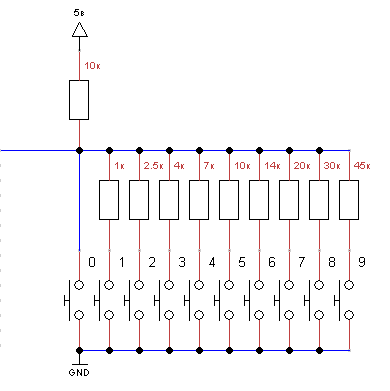
A simplified schematic diagram of the project is presented in the following figure. This figure does not show the power pins, and the LED is used as an actuator. The ATmega8 microcontroller was chosen as the manager.

To implement the project, it is necessary to use 4 outputs of the microcontroller, namely, data input from the “push-button field 0-9”, data input from the “save code” button, output for controlling the actuator “lock”, output confirmation of entering the digit “digit”.
')
To enter the code, a 0-9 field is used, made in the form of a voltage divider with a variable division factor. The coefficients are chosen as follows. When you press 0, a voltage of 0 volts, 1 0.5, 2 1.0, 3 1.5, 4 2.0, 5 2.5, .., 9 4.5, is formed at the output, and 5 volts in the free state.
To measure the potential from the “keypad 0-9” I used a microcontroller output connected to the ADC, this is “PINCO”. To be able to measure the voltage at the pinco pin, the ADC_ATmega8A and ADC PinCO blocks were added to the canvas.
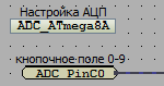
The “ADC_ATmega8A” block adjusts the parameters of the analog-to-digital converter built into the microcontroller, in the settings indicated the value of the reference voltage equal to the microcontroller supply voltage. So I set up the ADC for measuring voltage in the range of 0-5 volts. To obtain the voltage value at the pinco microcontroller output, I used the ADC PinCO block. At the output of the block, a discrete signal will be received in the range of 0-1023 proportional to the voltage value at the PINCO pin, with 0 volts corresponding to 0, and 5 volts to 1023. To bring the voltage to a convenient value, we used the “division” and “constant” ".
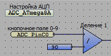
When dividing the input range 0-1023 by 90, we get the range convenient for us 0-11 range 0-11. Moreover, pressing the “button 0” will correspond to the value 0, 1-1, .., 9-9, and in the free state (no button is pressed) will be 11. To record the steady state event of the line, use the “delay” and block "equality".
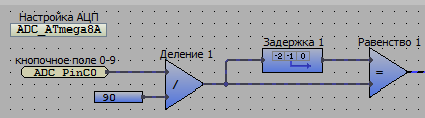
At the output of the block "delay" we get the value that was at the input of the block "delay" in the previous working cycle. If the values in the previous cycle and in the current one are equal, we fix the steady state of the line, while the output of the “equality” block will be a logical 1 (true) signal, otherwise 0 (false). To filter the value of 11 “free line state”, we use the “less” blocks, the constant 11 and the logical “AND” block.
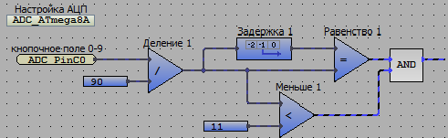
At the output of the “logical AND” block there will be a logical unit if the line is in a steady state and the value after the divider is less than 11. To limit the allowable input speed of values from the “push-button field 0-9”, this increases the noise immunity and limits the speed of the “code matching”, I use the “on delay” block and the “millisecond counter” block it needs.
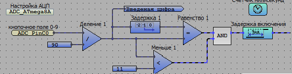
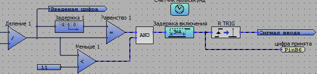
For the final formation of the “digit input” signal, we will track the rising edge and form a single “digit input” pulse using this signal. To do this, use the block "RTRIG".
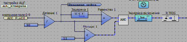
In order to read the scheme and reduce additional connecting lines, I will add “transitions” of connecting lines. The first transition is “entered digit”, the second is “digit input signal”. Enable the output control LED "digit accepted" in my circuit is the output of the microcontroller "PinB6".
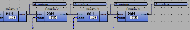
We will use the “entered digit” and “digit input signal” signals, as well as blocks for storing discrete numbers “memory” and organize the logic for storing the last entered numbers. In my case, I used four “memory” blocks, which would determine the secrecy of the lock in four digits.
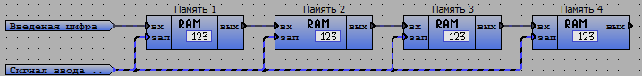
The logic works as follows: when a “symbol input signal” is received, the “entered digit” value will be recorded in the “memory 1” block, while the value previously contained in the “memory 1” block will be written into the “memory 2” block and so on. The “memory 1” - “memory 2” blocks will store the last entered digits. And in the “memory 1” block the last entered digit will be stored, in the “memory 2” block - the penultimate one, and so on. Add "transitions" for the values of the entered characters.
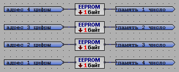
To store the lock code, we will use the non-volatile EEPROM memory of the microcontroller. Each digit of the code will be stored in a separate EEPROM cell. In our case, we will need 4 memory cells. Select the addresses of the EEPROM cells to store the code, for my project I selected cells 10, 11, 12, 13.

To read the value stored in the EEPROM cells, we will use the “read byte EEPROM” block.
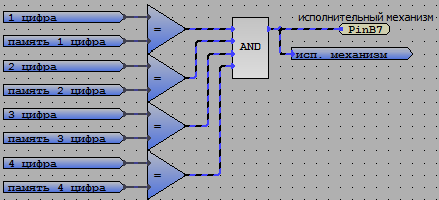
As a result, we have the digits entered from the “push-button field 0-9” and the digits obtained from the EEPROM cells, it remains to make a comparison of the digits and form a control signal to the actuators of the lock. For this task, I used the “equality” block and the “logical AND” block.
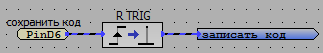
At this stage, the code lock logic is fully functional, the only thing left is to “teach” the microcontroller to independently save the lock code needed by the user in the EEPROM memory. For this task, I use an external signal “save code” and by this signal I will generate an EEPROM recording impulse, for this I will use the “PinD6” logic input blocks and the “RTRIG” block, and also create a corresponding transition for convenience.
Let's build the logic of writing data to the EEPROM, all the signals and data have already been formed, directly for writing data to the EEPROM we will use the “byte writing to EEPROM” block.

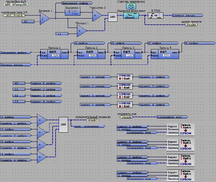
The logic of the code lock is described, the general view of the project is as follows.
We collect the project:
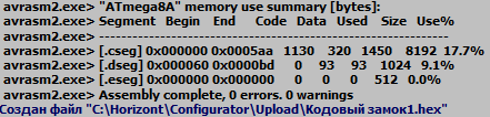
After assembling the project, we received an executable * .hex file of 1450 bytes in size, we conclude that we can use a microcontroller with a flash memory size of 2 kb.
Testing the project:
A simplified schematic diagram of the project is presented in the following figure. This figure does not show the power pins, and the LED is used as an actuator. The ATmega8 microcontroller was chosen as the manager.
To implement the project, it is necessary to use 4 outputs of the microcontroller, namely, data input from the “push-button field 0-9”, data input from the “save code” button, output for controlling the actuator “lock”, output confirmation of entering the digit “digit”.
')
To enter the code, a 0-9 field is used, made in the form of a voltage divider with a variable division factor. The coefficients are chosen as follows. When you press 0, a voltage of 0 volts, 1 0.5, 2 1.0, 3 1.5, 4 2.0, 5 2.5, .., 9 4.5, is formed at the output, and 5 volts in the free state.
To measure the potential from the “keypad 0-9” I used a microcontroller output connected to the ADC, this is “PINCO”. To be able to measure the voltage at the pinco pin, the ADC_ATmega8A and ADC PinCO blocks were added to the canvas.
The “ADC_ATmega8A” block adjusts the parameters of the analog-to-digital converter built into the microcontroller, in the settings indicated the value of the reference voltage equal to the microcontroller supply voltage. So I set up the ADC for measuring voltage in the range of 0-5 volts. To obtain the voltage value at the pinco microcontroller output, I used the ADC PinCO block. At the output of the block, a discrete signal will be received in the range of 0-1023 proportional to the voltage value at the PINCO pin, with 0 volts corresponding to 0, and 5 volts to 1023. To bring the voltage to a convenient value, we used the “division” and “constant” ".
When dividing the input range 0-1023 by 90, we get the range convenient for us 0-11 range 0-11. Moreover, pressing the “button 0” will correspond to the value 0, 1-1, .., 9-9, and in the free state (no button is pressed) will be 11. To record the steady state event of the line, use the “delay” and block "equality".
At the output of the block "delay" we get the value that was at the input of the block "delay" in the previous working cycle. If the values in the previous cycle and in the current one are equal, we fix the steady state of the line, while the output of the “equality” block will be a logical 1 (true) signal, otherwise 0 (false). To filter the value of 11 “free line state”, we use the “less” blocks, the constant 11 and the logical “AND” block.
At the output of the “logical AND” block there will be a logical unit if the line is in a steady state and the value after the divider is less than 11. To limit the allowable input speed of values from the “push-button field 0-9”, this increases the noise immunity and limits the speed of the “code matching”, I use the “on delay” block and the “millisecond counter” block it needs.
For the final formation of the “digit input” signal, we will track the rising edge and form a single “digit input” pulse using this signal. To do this, use the block "RTRIG".
In order to read the scheme and reduce additional connecting lines, I will add “transitions” of connecting lines. The first transition is “entered digit”, the second is “digit input signal”. Enable the output control LED "digit accepted" in my circuit is the output of the microcontroller "PinB6".
We will use the “entered digit” and “digit input signal” signals, as well as blocks for storing discrete numbers “memory” and organize the logic for storing the last entered numbers. In my case, I used four “memory” blocks, which would determine the secrecy of the lock in four digits.
The logic works as follows: when a “symbol input signal” is received, the “entered digit” value will be recorded in the “memory 1” block, while the value previously contained in the “memory 1” block will be written into the “memory 2” block and so on. The “memory 1” - “memory 2” blocks will store the last entered digits. And in the “memory 1” block the last entered digit will be stored, in the “memory 2” block - the penultimate one, and so on. Add "transitions" for the values of the entered characters.
To store the lock code, we will use the non-volatile EEPROM memory of the microcontroller. Each digit of the code will be stored in a separate EEPROM cell. In our case, we will need 4 memory cells. Select the addresses of the EEPROM cells to store the code, for my project I selected cells 10, 11, 12, 13.
To read the value stored in the EEPROM cells, we will use the “read byte EEPROM” block.
As a result, we have the digits entered from the “push-button field 0-9” and the digits obtained from the EEPROM cells, it remains to make a comparison of the digits and form a control signal to the actuators of the lock. For this task, I used the “equality” block and the “logical AND” block.
At this stage, the code lock logic is fully functional, the only thing left is to “teach” the microcontroller to independently save the lock code needed by the user in the EEPROM memory. For this task, I use an external signal “save code” and by this signal I will generate an EEPROM recording impulse, for this I will use the “PinD6” logic input blocks and the “RTRIG” block, and also create a corresponding transition for convenience.
Let's build the logic of writing data to the EEPROM, all the signals and data have already been formed, directly for writing data to the EEPROM we will use the “byte writing to EEPROM” block.
The logic of the code lock is described, the general view of the project is as follows.
We collect the project:
After assembling the project, we received an executable * .hex file of 1450 bytes in size, we conclude that we can use a microcontroller with a flash memory size of 2 kb.
Testing the project:
Source: https://habr.com/ru/post/304830/
All Articles