DLMS / COSEM is an open protocol for data exchange with metering devices. Part 2: interface classes, metering device model
This part of a series of publications devoted to the DLMS / COSEM protocol defines the interface classes and their instances, discusses how to refer to COSEM objects, describes the structure of the description of interface classes and the COSEM class diagram. It describes the model of the metering device, describes the role of the logic control unit, and also provides a brief description of the object identification system (OBIS).
Links to published parts of a publication series
- DLMS / COSEM is an open protocol for data exchange with metering devices. Part 1: Overview
- DLMS / COSEM is an open protocol for data exchange with metering devices. Part 2: interface classes, metering device model
Interface classes
Interface classes are one of the key elements of the DLMS / COSEM protocol, providing interoperability between data collection systems and metering devices from different manufacturers. In other words, the interoperability of data acquisition and metering systems, i.e. the ability to interact with each other is achieved, in particular, through the use of interface classes. Because both the data acquisition system and the metering device have a single presentation of information.
Before defining the interface class, we first consider its instances, i.e. COSEM objects. COSEM objects are a collection of attributes and methods. Attributes reflect the characteristics of an object, and attribute values can influence the behavior of an object. The first attribute ( logical_name ) of any object contains as a value a logical name that identifies the object. Object methods allow you to either view or change attribute values.
Objects that have common characteristics (attributes and methods) constitute an interface class, i.e. interface class gives a description of the characteristics inherent in all objects of this interface class.
')
The above is illustrated in Figure 1 .

Figure 1 - Interface class and its instances
In Figure 1, the metering device contains two registers, i.e. two instances of the interface class "Register". Moreover, both instances represent different information, so a COSEM object with a logical name
You can access the COSEM object and read / write a specific attribute or execute a certain method in two ways, either through its logical name ( LN referencing ) or through a short name ( SN referencing ).
When accessing a COSEM object via a logical name, the attribute reference consists of the class identifier ( class_id ), the value of the logical_name attribute and the attribute_index parameter, and the method reference is of the class identifier ( class_id ), the value of the logical_name attribute, and the method_index parameter, where:
- attribute_index - attribute index (sequence number). Attribute indices are defined in the description of the interface class, and are numbered starting with 1.
- method_index - index (sequence number) of the method. Method indices are defined in the description of the interface class, and are numbered starting with 1.
The description of the interface classes follows the structure shown in Figure 2 .
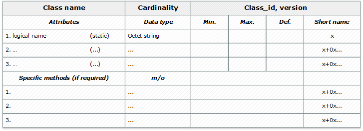
Figure 2 - Structure of the interface class description
The definitions used in the interface class description structure are as follows:
Class name
The name of the interface class (for example, “Register”, “Data”, “Clock”, etc.).Cardinality
The number of instances of the interface class in a logical unit.Class_id
ID of the interface class.Version
The version of the interface class.Attributes
Attributes inherent in this interface class. Attributes can be both dynamic ( dyn. ), Their values are updated by the meter itself, and static ( static ), in this case the meter cannot update their values itself (for example, configuration data).Logical name
The value of this attribute is represented as a string of bytes ( octet string ), the attribute_index of this attribute is always 1. The value of this attribute identifies the instances of the interface class, i.e. COSEM objects.Data type
The data types for the attribute.Min.
The minimum attribute value.Max.
Maximum attribute value.Def.
The default attribute value.Short name
The short name of the attribute or method if SN referencing is used .Specific method
Methods inherent in this interface class.m / o
Type of method: mandatory (m) or optional (o).An example of the interface class "Register" is shown in Figure 3 , and its description in Figure 4 .

Figure 3 - interface class "Register"

Figure 4 - Description of the interface class "Register"
All interface classes can be divided into 12 groups, the names of these groups, as well as the names of the classes that are included in them, are shown in the class diagram ( Figure 5 [clickable] ).

Figure 5 - Diagram of interface classes (clickable)
A brief description of the interface classes can be found in an abbreviated version of the blue book .
Metering device model
The DLMS / COSEM protocol is based on a client-server architecture. The metering device performs the role of a server, and the data collection system acts as a client. The initiator of the exchange of information is the data collection system, the metering device only provides the required information in response to a request from the data collection system. However, in certain situations the metering device itself may initiate data exchange with the data acquisition system.
Figure 6 shows the model of the metering device. The metering device is a physical device ( COSEM physical device ), within which there is at least one logical device ( Management logical device ). The use of multiple logic devices allows for the implementation of combined metering devices. For example, a heat meter with a pulse input for measuring water consumption.
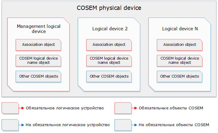
Figure 6 - Model of metering device DLMS / COSEM
The lower levels of the used protocol stack are responsible for addressing both physical and logical devices. For example, when using the HDLC protocol at the link layer, the meter address is represented as a sequence of bytes, with three addressing schemes possible: single-byte (only the address of the logic device), two-byte (the address of the logical and physical device, the value of which does not exceed 127) and four-byte ( the address of the logical and physical device, the values of which exceed 127). More information about addressing using the HDLC protocol is found in chapter 8 of the green paper .
Each logical device has a unique LDN name, it is accessible either through the “SAP Assignment” interface class object, or through the COSEM “COSEM logical device name” object (as a rule, it is an instance of the “Data” interface class).
LDN is a string of bytes up to 16 bytes in size. The first three bytes are the manufacturer ID. The manufacturer guarantees that an LDN starting with three bytes and the 13 bytes following them are unique.
An object containing an LDN is necessarily present in the logical device, as, incidentally, are also Association objects.
In order for a client to gain access to COSEM objects located on the server (metering device), it must be associated with it. The association process determines the partners (client and server) and the context in which they will be linked. The main elements of the context are:
- Application context The method of accessing COSEM objects ( LN or SN referencing ) and the ability to encrypt the transmitted information is determined.
- Authentication mechanism. The way to access the logical device is determined: open access ( lowest level security ), password access ( low level security ), authentication access ( high level security using AES128 / MD5 / SHA-1 / GMAC / SHA-256 / ECDSA ).
- XDLMS context. The application level parameters are defined.
- Objects of the interface class “Association SN” - in the case of SN referencing ;
- Objects of the interface class “Association LN” - in the case of LN referencing .
The list of visible COSEM objects is in the object_list attribute of the corresponding association object.
As mentioned earlier, in each physical device there is always at least one logical device, called the Management logical device . It has a reserved address ( 0x01 ) and maintains the association of the public client with the lowest level of secrecy. Thus, the logical control unit is always in the public domain.
The main role of the logical control unit is the representation of the internal structure of the physical device and the support of event notifications in the metering device.
The internal structure of the physical device is represented by the “SAP assignment” interface class object and contains the SAP and LDN of each logical device. In essence, SAP is the address of the logical device. Thus, in order to find out how many logical devices are in the metering device, as well as get them SAP and LDN, you must read the attributes of the “SAP assignment” interface class object. This object is also in the public domain.
Object Identification System (OBIS code)
The object identification system determines the identification codes for widely used data elements in measuring devices. OBIS provides unique identifiers for all data within a measuring device, including identifiers not only of the measured values, but also abstract value identifiers used to configure or obtain information about the behavior of the measuring equipment.
For instances of the COSEM interface classes, the OBIS code is used as the logical name of the COSEM object and uniquely identifies the information that this object represents.
The OBIS code, which is the first attribute value of any COSEM object, is a numeric combination of six groups of digits. Each group contains a number from the range from 0 to 255. The structure of the OBIS code and the purpose of each group of numbers are as follows:
Group A
The value of this group determines the type of energy source with which the measurement is connected (electricity, heat, gas, etc.) or abstract data. Under the abstract data refers to the information that is inherent in the metering device, and not the measured value. For example, abstract objects include an object representing the name of a logical device, association objects, an object representing the firmware version of the metering device, etc.Group B
The value of this group, as a rule, determines the number of the measuring channel, but can also determine the number of the communication channel, and in some cases, other elements. The interpretation of the values of this group does not depend on the value of group A.Group C
The value of this group determines the name of the measured value (current, voltage, power, volume, temperature) or abstract data. The interpretation of the value of this group depends on the value of group A. The processing, classification, and storage methods are determined by the values of groups D, E, and F. For abstract data, the values of groups D, E, and F provide further classification of data determined by the values of groups A, B, and C.Group D
The value of this group determines the types, or the result of processing of physical quantities, determined by the values of groups A and C, in accordance with various specific algorithms.Group E
The value of this group determines the further processing or classification of values determined by the values of groups A - D.Group f
The value of this group determines the accumulated data, identified by the values of groups A - E, according to different calculation periods.The meanings of standard OBIS codes are available for download as an excel document from the official DLMS UA website, for more information about OBIS, see Chapter 7 of the Blue Book .
Source: https://habr.com/ru/post/303606/
All Articles