Experience useful modification UEFI: return Thinkpad W520 legitimate support for fast memory
To begin with the background:
Some time ago I bought a used Lenovo Thinkpad W520 laptop on Ebay. As is known, the W-series is very powerful laptops, glands in which will give odds to many more modern machines. Of course, I began to equip it for myself, and, in particular, I decided to upgrade the existing memory with everything that was available, and there were a lot of available: 2 free DDR3-1600 slats from the old laptop - 4 and 8 gigabytes. Looking at what was installed by the seller, I found that out of 3 installed slats 2 were DDR3-1600, and one was 1333. Given that the first two were 8 gigabytes each, and the last 2 gigabytes, I decided to get rid of it . Calculating to get after the upgrade 8 + 8 + 8 + 4 = 28 gigabytes DDR3-1600 in a working laptop, Ifilled everything with saliva and quickly connected it all. And I got 28 gigabytes ... DDR3-1333. "What the ...", I thought, and got into Google.
After a brief search, I found that both officially and unofficially, the W520 only supports DDR3-1333, and the owners of faster memory were wasting money on it. I felt a little sad for all such owners, and I decided to try to get rid of this injustice, especially since the memory controller, as you know, in the processor, and installed in my Intel Core i7 2720QM model, officially supports DDR3-1600 .
And now some interesting details.
')
The solution to any complex task is to start with the collection of available information. I was pretty lucky here, I found an interesting page on Thinkwiki , which asserted that the modified BIOS I needed very much existed, but it was made by some cunning my compatriot named Oleh, and asked for it 1,500 rubles. I do not mind, there is a demand - there is a proposal, but we seem to have a mustache ourselves, and we can fix and solder, and we can figure it out in the code, we will try to save one and a half kilo on ice cream.
Actually, the task for me was almost solved, the page on Thinkwiki contains a link to a rather well-known resource BIOS-Mods, where the patch is actually filed on a platter, you need to do this:
But when I tried to use this solution “in the forehead”, a bummer was waiting for me - such a sequence of bytes in the firmware was not found at all, either by this offset or by some other. I had to roll up my sleeves and dig deeper, that is, I still needed to figure out what this code does and what it needs to be fixed for.
First of all, I will say that the sequence 66 0F 1F 44 00 00 0F 1F 00 66 0F 1F 44 00 00 0F 1F 80 00 00 00 00 does not do anything. That is, it can just as well be replaced with the nop (0x90) sequence, as CodeRush later pointed out to me, but this is what I am looking forward to. For now, we note that this sequence disables the desired code, and does not change it.
I proceeded from the fact that the patch that is described in BIOS-Mods is correct, just from a different laptop model, and in my case something will be a little wrong.
The source code for the fix in the SandyBridgePhx.efi file is:
535h here is nothing more than the clock frequency in megahertz, 1333 in decimal number system. Since this is a typical value, I extracted SandyBridgePhx.efi from the UEFI Tool firmware , took radare2 and looked for 535h in this file (do not forget about little endian ):
Listing radare2
For some reason, our 1333 megahertz meet 2 times very close. We look, what is there is:
Tilde marked line with the desired value. It can be seen that the code as a whole corresponds to the desired, the only thing that is different is the registers. In general, everything seems to be simple, but there is a second value ... Going on the offset 0x00001839 and we see there exactly the same sequence of commands, 1 in 1. WTF? What patch something? And most importantly, why do I need to disable this code, and not change 1333 to 1600, say? To explain this, my rudimentary knowledge of x86 assembler was not enough. I turned for help to my friend-reverser Rumata888 . He, by virtue of the profession, has access to the normal licensed version of IDA Pro, than did not fail to take advantage.
Literally one screenshot from IDA, which explained everything to me:

42Bh, 535h, 640h and 74Bh are, as you probably already guessed, memory frequencies: 1067, 1333, 1600 and 1867 MHz, respectively. That is, of course, the blocks that set the desired memory frequency (most likely, reading it from the SPD and the saved settings). But then the most interesting thing happens: regardless of what we posed there, the transition at the 182Ch shift occurs. And that same second sequence of commands is being executed, which confused me. Ladies and gentlemen, we have the most common crutch: first we honestly analyze what kind of frequency should be set, and then we take a sledgehammer and beat 1333 MHz tightly. Naturally, it is necessary to get rid of the crutch (which was done on BIOS-Mods), and after that everything will work.
After the clarity came, I, in order to reinforce my confidence, asked CodeRush , as the chief public expert on UEFI, to check if I did everything as it should, for which I received the already mentioned advice that everything looks fine, but it is better to throw out a sly site ( 66 0F 1F 44 00 00 0F 1F 00 66 0F 1F 44 00 00 0F 1F 80 00 00 00 00) and just hammer an unnecessary crutch with nop-s. Well, the recommendation toprotect yourself to make a backup, better programmer.
Then there were difficulties, because of which the patch had to be postponed for almost a month. At first I was waiting for a parcel with a programmer and a clothespin for SPI-Flash firmware without soldering, then I tried to flash a modified firmware file with a programmer after backup with a programmer. Immediately I inform you: no fig came out. Apparently, you can only sew if there is a difference in the versions, and 1.42 over 1.42 proprietary software will not sew. I had to do everything in the most oak way: fix the backup that was merged from the flash drive and fill it back with a programmer.
Brief instructions for self-correction of a fatal flaw.
Now the summary, for those who do not want to read my writings above, is a working way to unlock memory on the Thinkpad W520 (and other similar models, in particular the T520 and, probably, the X220 and some other models on Sandy Bridge):
I express my gratitude to CodeRush and Rumata888 , this note would never exist without them, and I would have remained ignorant.
If someone takes to follow my example, I am ready to publish ready-made recipes (what to change, at what offset) for other notebook models.
UPD: Added the missing byte in the instructions, I apologize to all who may be affected. Thank you arozanov for your attention.
Some time ago I bought a used Lenovo Thinkpad W520 laptop on Ebay. As is known, the W-series is very powerful laptops, glands in which will give odds to many more modern machines. Of course, I began to equip it for myself, and, in particular, I decided to upgrade the existing memory with everything that was available, and there were a lot of available: 2 free DDR3-1600 slats from the old laptop - 4 and 8 gigabytes. Looking at what was installed by the seller, I found that out of 3 installed slats 2 were DDR3-1600, and one was 1333. Given that the first two were 8 gigabytes each, and the last 2 gigabytes, I decided to get rid of it . Calculating to get after the upgrade 8 + 8 + 8 + 4 = 28 gigabytes DDR3-1600 in a working laptop, I
After a brief search, I found that both officially and unofficially, the W520 only supports DDR3-1333, and the owners of faster memory were wasting money on it. I felt a little sad for all such owners, and I decided to try to get rid of this injustice, especially since the memory controller, as you know, in the processor, and installed in my Intel Core i7 2720QM model, officially supports DDR3-1600 .
And now some interesting details.
')
The solution to any complex task is to start with the collection of available information. I was pretty lucky here, I found an interesting page on Thinkwiki , which asserted that the modified BIOS I needed very much existed, but it was made by some cunning my compatriot named Oleh, and asked for it 1,500 rubles. I do not mind, there is a demand - there is a proposal, but we seem to have a mustache ourselves, and we can fix and solder, and we can figure it out in the code, we will try to save one and a half kilo on ice cream.
Actually, the task for me was almost solved, the page on Thinkwiki contains a link to a rather well-known resource BIOS-Mods, where the patch is actually filed on a platter, you need to do this:
At offset 0x1810 replace byte order
on
8B 85 C8 FC FF FF 8B 48 09 66 C7 41 01 35 05 C6 85 C2 FC FF FF 0Con
66 0F 1F 44 00 00 0F 1F 00 66 0F 1F 44 00 00 0F 1F 80 00 00 00 00But when I tried to use this solution “in the forehead”, a bummer was waiting for me - such a sequence of bytes in the firmware was not found at all, either by this offset or by some other. I had to roll up my sleeves and dig deeper, that is, I still needed to figure out what this code does and what it needs to be fixed for.
First of all, I will say that the sequence 66 0F 1F 44 00 00 0F 1F 00 66 0F 1F 44 00 00 0F 1F 80 00 00 00 00 does not do anything. That is, it can just as well be replaced with the nop (0x90) sequence, as CodeRush later pointed out to me, but this is what I am looking forward to. For now, we note that this sequence disables the desired code, and does not change it.
I proceeded from the fact that the patch that is described in BIOS-Mods is correct, just from a different laptop model, and in my case something will be a little wrong.
The source code for the fix in the SandyBridgePhx.efi file is:
| hex | asm |
|---|---|
| 8B 95 C8 FC FF FF | mov edx, [ebp + var_338] |
| 8B 42 09 | mov eax, [edx + 9] |
| 66 C7 41 01 35 05 | mov word ptr [eax + 1], 535h |
| C6 85 C2 FC FF FF 0C | mov [ebp + var_33E], 0Ch |
535h here is nothing more than the clock frequency in megahertz, 1333 in decimal number system. Since this is a typical value, I extracted SandyBridgePhx.efi from the UEFI Tool firmware , took radare2 and looked for 535h in this file (do not forget about little endian ):
Listing radare2
[0x00000000]> /x 3505
Searching 2 bytes in [0x0-0x2406]
hits: 2
0x000017d6 hit0_0 3505
0x00001839 hit0_1 3505
For some reason, our 1333 megahertz meet 2 times very close. We look, what is there is:
| Bias | hex | asm |
|---|---|---|
| 0x000017c9 | 8B 85 C8 FC FF FF | mov eax, dword [ebp - 0x338] |
| 0x000017cf | 8B 48 09 | mov ecx, dword [eax + 9] |
| 0x000017d2 ~ | 66 C7 41 01 35 05 | mov word [ecx + 1], 0x535 |
| 0x000017d8 | C6 85 C2 FC FF FF 0C | mov byte [ebp - 0x33e], 0xc |
Tilde marked line with the desired value. It can be seen that the code as a whole corresponds to the desired, the only thing that is different is the registers. In general, everything seems to be simple, but there is a second value ... Going on the offset 0x00001839 and we see there exactly the same sequence of commands, 1 in 1. WTF? What patch something? And most importantly, why do I need to disable this code, and not change 1333 to 1600, say? To explain this, my rudimentary knowledge of x86 assembler was not enough. I turned for help to my friend-reverser Rumata888 . He, by virtue of the profession, has access to the normal licensed version of IDA Pro, than did not fail to take advantage.
Literally one screenshot from IDA, which explained everything to me:
42Bh, 535h, 640h and 74Bh are, as you probably already guessed, memory frequencies: 1067, 1333, 1600 and 1867 MHz, respectively. That is, of course, the blocks that set the desired memory frequency (most likely, reading it from the SPD and the saved settings). But then the most interesting thing happens: regardless of what we posed there, the transition at the 182Ch shift occurs. And that same second sequence of commands is being executed, which confused me. Ladies and gentlemen, we have the most common crutch: first we honestly analyze what kind of frequency should be set, and then we take a sledgehammer and beat 1333 MHz tightly. Naturally, it is necessary to get rid of the crutch (which was done on BIOS-Mods), and after that everything will work.
After the clarity came, I, in order to reinforce my confidence, asked CodeRush , as the chief public expert on UEFI, to check if I did everything as it should, for which I received the already mentioned advice that everything looks fine, but it is better to throw out a sly site ( 66 0F 1F 44 00 00 0F 1F 00 66 0F 1F 44 00 00 0F 1F 80 00 00 00 00) and just hammer an unnecessary crutch with nop-s. Well, the recommendation to
Then there were difficulties, because of which the patch had to be postponed for almost a month. At first I was waiting for a parcel with a programmer and a clothespin for SPI-Flash firmware without soldering, then I tried to flash a modified firmware file with a programmer after backup with a programmer. Immediately I inform you: no fig came out. Apparently, you can only sew if there is a difference in the versions, and 1.42 over 1.42 proprietary software will not sew. I had to do everything in the most oak way: fix the backup that was merged from the flash drive and fill it back with a programmer.
Brief instructions for self-correction of a fatal flaw.
Now the summary, for those who do not want to read my writings above, is a working way to unlock memory on the Thinkpad W520 (and other similar models, in particular the T520 and, probably, the X220 and some other models on Sandy Bridge):
- We buy / look for the above-mentioned clothespin and programmer. Naturally, the programmer can also be used by another one, in particular, the very popular Raspberry Pi , and the clothespin can be replaced by soldering-soldering the SPI Flash chip. But this is up to you - suddenly you have the Grandmaster soldering skill and the soldering station is always at hand. For those who are not friends with soldering, I highly recommend clothespins.
- We connect (or unsolder and connect) the flash drive, do not confuse the connection, the 1st wire on the clothespin is highlighted, on the chip the 1st pin is marked with a dot. The flash drive itself is here (marked by an arrow):
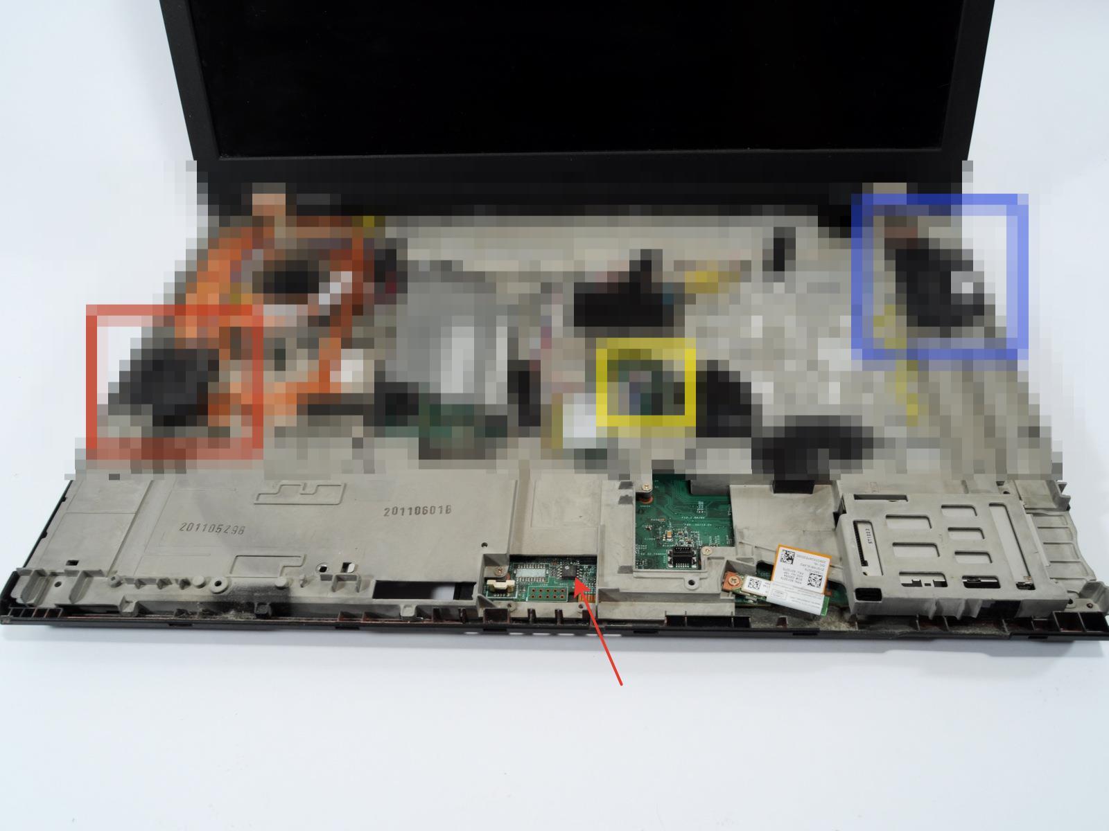
Instructions on how to get there, with pictures - We merge the flash drive backup, just in case we check that it is not empty and the size is correct, the W520 flash drive is 64 Mbit in size, i.e. 8 mebibyte
or megabyte if you are retrograde. It is even better to use the check function of the flasher, if there is one. If not - can take another software? - Open the Hex-editor backup, look for Hex-sequence of bytes.Here is such8B 85 C8 FC FF FF 8B 48 09 66 C7 41 01 35 05 C6 85 C2 FC FF FF 0C
We find it in the backup 4 times. The last two, which are closer to the end, should not be touched - they are for initializing memory in emergency mode (the SandyBridgePhxCrisis.efi file, if anyone is interested). From the first two, as follows from the text above, we are interested in the second occurrence of this sequence. My location on the W520 starts at offset 53A834h. - Replace all bytes with nop (90h).
- We flash our backup back to the flash drive, check that everything was done correctly (this is where the check function is absolutely indispensable).
- We solder the flash drive back (or simply remove the clothespin), assemble the laptop, boot up, run CPU-Z, and take a screenshot like this:
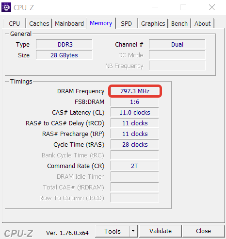
- PROFIT!
I express my gratitude to CodeRush and Rumata888 , this note would never exist without them, and I would have remained ignorant.
If someone takes to follow my example, I am ready to publish ready-made recipes (what to change, at what offset) for other notebook models.
UPD: Added the missing byte in the instructions, I apologize to all who may be affected. Thank you arozanov for your attention.
Source: https://habr.com/ru/post/303602/
All Articles