Experiments with Arduino 101
Once, on a hot winter day, on Christmas Eve, I was irresistibly drawn to do something interesting. I had a decent supply of foie gras (in the south-west of France, where I live, produce a lot of this delicacy), a good film and the Arduino 101 board. I decided to experiment with it. Join now!

Arduino 101
You may have heard that the Arduino 101 board was presented at the Maker Faire Rom 2015 exhibition. I happened to attend this wonderful event and see the presentation with my own eyes.
The first thing I want to say about the Arduino 101, is that the device is, despite the miniature and low price, perfectly equipped. Namely, it has a 32-bit Intel Quark microcontroller, which makes it economical. It has 384 KB of flash memory, 80 KB of SRAM (24 KB are available for sketches). The Arduino 101 is equipped with a DSP sensor hub, Bluetooth LE and a 6-axis combined sensor with an accelerometer and a gyroscope. All this thanks to the Intel Curie module.
')
So, experimenting with the Arduino 101, I decided to test its capabilities in working with digital and analog devices, to see what can be done with the gyro sensor (IMU) and the Bluetooth LE module (BLE).
So, where do we start? To begin with, we connect the Arduino 101 to a computer using a USB cable, then we will download the latest version of the Arduino IDE (1.6.7. In my case) and install the necessary package using the card manager.

Starting the card manager
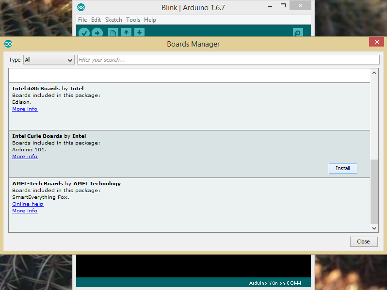
Package installation
After the installation is completed, a new board should appear in the menu - “Arduino 101”.

Arduino 101 in the menu
Before you begin, you need to specify the COM port with which the board is associated.

COM port selection
The development environment is installed, the board is connected to the computer, now let's try the first example - “Blink”.
To run an example of additional devices to the board will not have to connect. It uses a built-in LED that will flash if everything goes as needed. Let's load an example from the corresponding menu.

Download sample from menu
When the code is opened in the editor, you need to click on the “Upload” button (an arrow is drawn on it) to upload the sketch collected from it to the board.
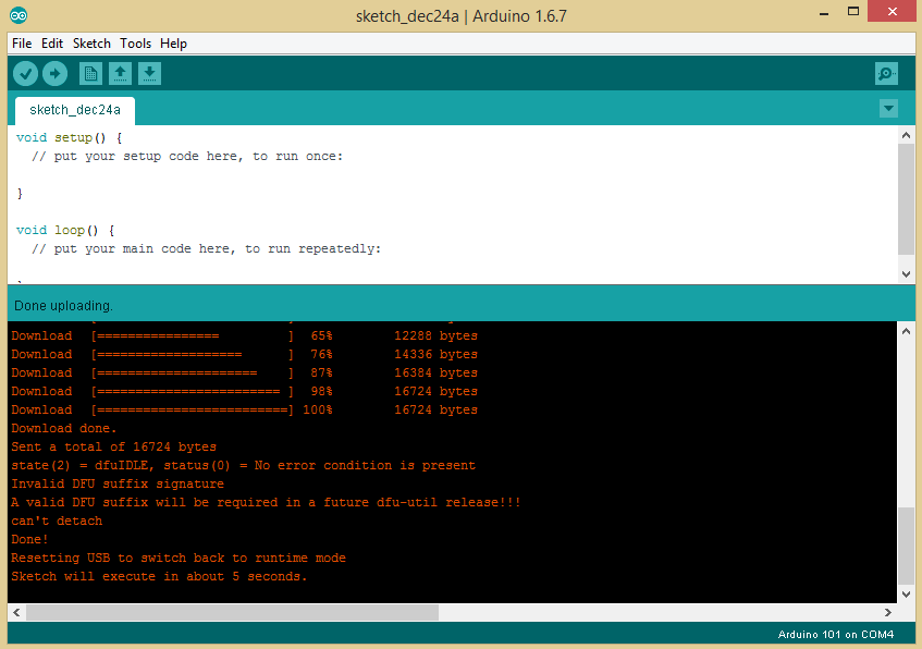
Uploading a sketch to the board
After pressing the button, the code is compiled and uploaded to the board via USB. If everything is done correctly, after a few seconds the LED on the Arduino 101 will flash. You can make changes to the code, for example - change the blinking period of the LED. After that, unload it again on the board and evaluate the work of the modified version.
So, we figured out the flashing LED, we will now connect some sensor to the board, but before we do this, we will connect an expansion card to the Arduino 101.
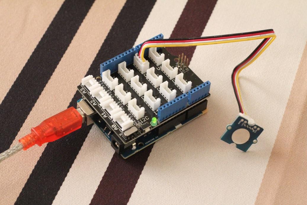
I have a Grove Starter Kit Plus , I chose a sensor from there, and decided to start with something simple. For example - from a potentiometer, which in the documentation of the Grove is called "Rotary Angle Sensor". The sensor is connected to the analog connector, namely, to A0, and then, in real time, we will read its readings.

Potentiometer connection
Download the “AnalogReadSerial” example from the menu.

Sample download
Unload the sketch to the board and open the serial port monitor (“Serial Monitor”) from the Tools menu.

Potentiometer reading
Now in the monitor window you can see the data from the potentiometer, which changes when you turn its knob.
And here is another useful feature - plotting graphs from analog data using the “Serial Plotter” tool (it can be found in the “Tools” menu). The graph is displayed in real time.

Data visualization
There are analog sensors, there are digital. In the documentation for the device you can find instructions on this, as well as information on how to use this or that sensor.
Test a simple touch sensor from the Grove kit. Connect it to the D2 digital connector and load the “DigitalReadSerial” example.
Touch sensor connection
After downloading the sketch to the board in the monitor of the serial port, you can see the zeros and ones. "0" - there is no touch, "1" - there is a touch. Nothing else appears here. The thing is that the data comes from a binary digital sensor.

Touch Sensor Readings
Since the Arduino 101 uses the Intel Curie module, our service is a gyro sensor. In this experiment, you do not need to connect anything to the board, since the sensor is already built into it.
Open the example “RawIMUDataSerial”, unload it onto the board, launch the serial port monitor and shake the device. In the monitor it will be possible to observe six groups of indicators. The sensor has six degrees of freedom, as it is a combination of an accelerometer and a gyroscope.

Raw data embedded sensor
These data can be processed by means of the board in order to ascertain whether the movements are, for example, steps or strikes. Take a look at the example of “ShockDetect”, which gives the monitor the processed data about the blows.

Analysis of sensor readings performed on the board
Want more examples? Take a look here .
Thanks to the Intel Curie module, the Arduino 101 is equipped with Bluetooth LE. Using Bluetooth is very simple, no need for external BT transmitters.
Download the BatteryMonitor example and connect it to the analog connector A0, for example, a potentiometer. In the sketch, the potentiometer data is taken and sent as a Bluetooth LE message. In the framework of the example, they are treated as the charge level of a certain battery. Bluetooth LE has standard profiles, for example, for data on heart rate or battery level. We will use the latter.
When running the example, the board expects pairing with a BLE device. Here you can use a smartphone or laptop with Bluetooth LE support and initiate pairing with it with BatteryMonitorSketch.

Start connecting via Bluetooth
During the pairing process, you will see the device name (Genuino 101).

Pairing with Genuino 101
So, the device is connected to a laptop on Windows. Now you need an application that will be used by the BLE libraries for reading data that is generated by a sketch that emulates a battery charge sensor. I installed the Newbit BLE Tool from the Windows App Store. Then - I chose the BLE device and service with the ID "* 180f *". Such an ID means that we are connecting to a battery charge sensor (a list with examples of service identifiers can be seen in the left part of the window).

Service selection
Now that everything is ready, you can scroll the window to the right and look at the data that the sketch produces. In addition, changes to this indicator can be subscribed to and receive data as they are updated.
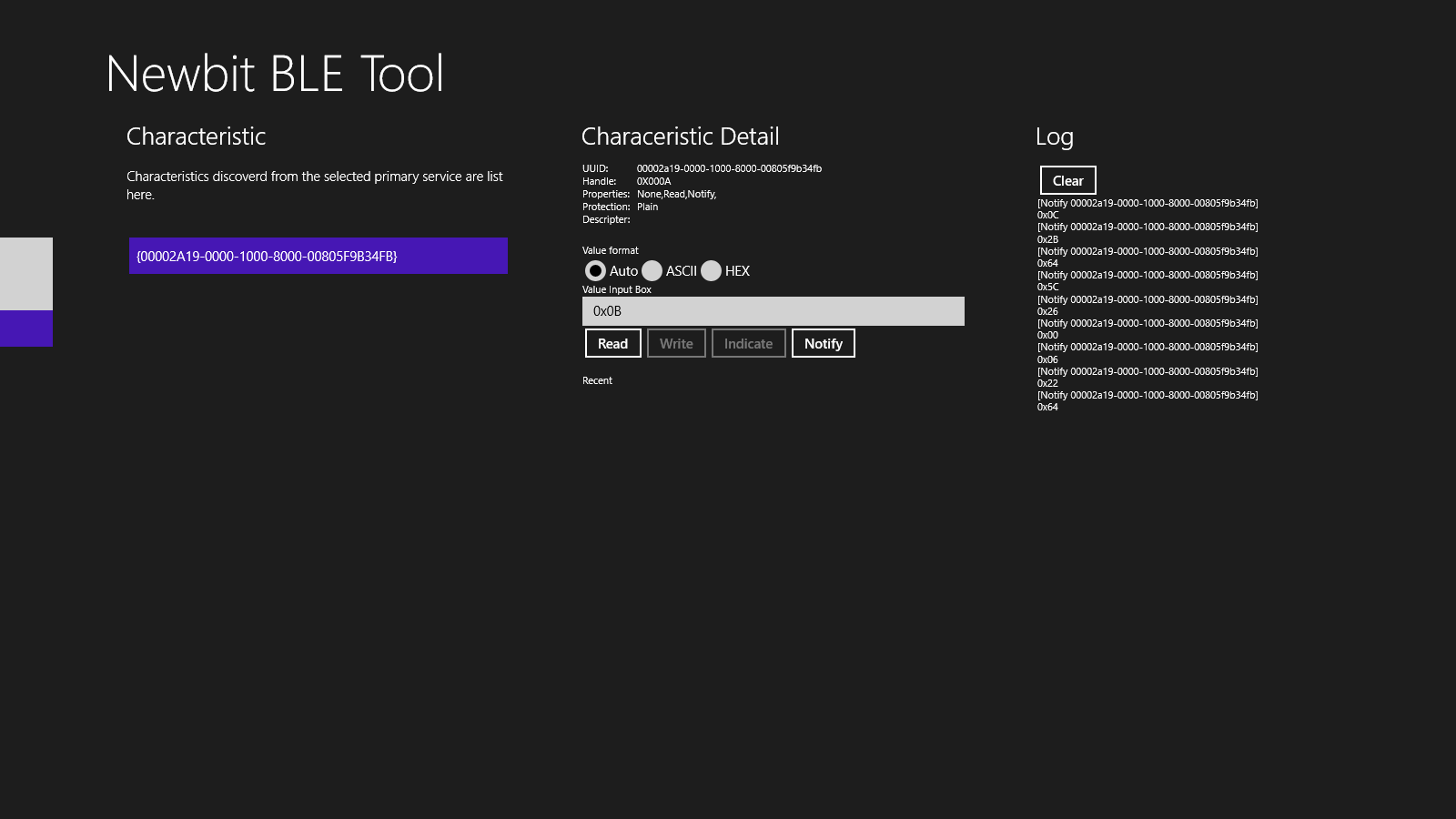
Bluetooth sensor readings
The Arduino 101, also called the Genuino 101, is easy to use, as one would expect from an Arduino-compatible device. You can write sketches for it using IDE Arduino, it is suitable for sets of sensors and other modules for Arduino. In addition, it is worth remembering that the Arduino is not only a device and development environment, but also a community of enthusiasts who willingly share knowledge and experience.
In addition to the standard features for Arduino boards, the Arduino 101 has very interesting built-in modules - Bluetooth LE and a combination of a gyroscope and an accelerometer.
The above makes the Arduino 101 an excellent choice for those who are just beginning to master the development of devices based on microcontrollers. But the board we are talking about is not just for beginners. It is also a powerful platform for professionals, which allows you to quickly assemble prototypes of smart devices for the Internet of things.
If the prototype built on the Arduino 101 works correctly, then, guided by the same ideas, you can create your own product using the Intel Curie platform. The device on this platform will be equipped with the same microcontroller, will have the same communication capabilities as the Arduino 101. As a result, thanks to the Arduino 101 we get a simple, fast and cheap way to go from prototypes to mass production of IoT solutions.
Arduino 101
You may have heard that the Arduino 101 board was presented at the Maker Faire Rom 2015 exhibition. I happened to attend this wonderful event and see the presentation with my own eyes.
The first thing I want to say about the Arduino 101, is that the device is, despite the miniature and low price, perfectly equipped. Namely, it has a 32-bit Intel Quark microcontroller, which makes it economical. It has 384 KB of flash memory, 80 KB of SRAM (24 KB are available for sketches). The Arduino 101 is equipped with a DSP sensor hub, Bluetooth LE and a 6-axis combined sensor with an accelerometer and a gyroscope. All this thanks to the Intel Curie module.
')
So, experimenting with the Arduino 101, I decided to test its capabilities in working with digital and analog devices, to see what can be done with the gyro sensor (IMU) and the Bluetooth LE module (BLE).
Hello world
So, where do we start? To begin with, we connect the Arduino 101 to a computer using a USB cable, then we will download the latest version of the Arduino IDE (1.6.7. In my case) and install the necessary package using the card manager.
Starting the card manager
Package installation
After the installation is completed, a new board should appear in the menu - “Arduino 101”.
Arduino 101 in the menu
Before you begin, you need to specify the COM port with which the board is associated.
COM port selection
The development environment is installed, the board is connected to the computer, now let's try the first example - “Blink”.
To run an example of additional devices to the board will not have to connect. It uses a built-in LED that will flash if everything goes as needed. Let's load an example from the corresponding menu.
Download sample from menu
When the code is opened in the editor, you need to click on the “Upload” button (an arrow is drawn on it) to upload the sketch collected from it to the board.
Uploading a sketch to the board
After pressing the button, the code is compiled and uploaded to the board via USB. If everything is done correctly, after a few seconds the LED on the Arduino 101 will flash. You can make changes to the code, for example - change the blinking period of the LED. After that, unload it again on the board and evaluate the work of the modified version.
Analog sensor
So, we figured out the flashing LED, we will now connect some sensor to the board, but before we do this, we will connect an expansion card to the Arduino 101.
I have a Grove Starter Kit Plus , I chose a sensor from there, and decided to start with something simple. For example - from a potentiometer, which in the documentation of the Grove is called "Rotary Angle Sensor". The sensor is connected to the analog connector, namely, to A0, and then, in real time, we will read its readings.
Potentiometer connection
Download the “AnalogReadSerial” example from the menu.
Sample download
Unload the sketch to the board and open the serial port monitor (“Serial Monitor”) from the Tools menu.
Potentiometer reading
Now in the monitor window you can see the data from the potentiometer, which changes when you turn its knob.
And here is another useful feature - plotting graphs from analog data using the “Serial Plotter” tool (it can be found in the “Tools” menu). The graph is displayed in real time.
Data visualization
Digital sensors
There are analog sensors, there are digital. In the documentation for the device you can find instructions on this, as well as information on how to use this or that sensor.
Test a simple touch sensor from the Grove kit. Connect it to the D2 digital connector and load the “DigitalReadSerial” example.
Touch sensor connection
After downloading the sketch to the board in the monitor of the serial port, you can see the zeros and ones. "0" - there is no touch, "1" - there is a touch. Nothing else appears here. The thing is that the data comes from a binary digital sensor.
Touch Sensor Readings
Gyroscopic sensor
Since the Arduino 101 uses the Intel Curie module, our service is a gyro sensor. In this experiment, you do not need to connect anything to the board, since the sensor is already built into it.
Open the example “RawIMUDataSerial”, unload it onto the board, launch the serial port monitor and shake the device. In the monitor it will be possible to observe six groups of indicators. The sensor has six degrees of freedom, as it is a combination of an accelerometer and a gyroscope.
Raw data embedded sensor
These data can be processed by means of the board in order to ascertain whether the movements are, for example, steps or strikes. Take a look at the example of “ShockDetect”, which gives the monitor the processed data about the blows.
Analysis of sensor readings performed on the board
Want more examples? Take a look here .
Bluetooth LE
Thanks to the Intel Curie module, the Arduino 101 is equipped with Bluetooth LE. Using Bluetooth is very simple, no need for external BT transmitters.
Download the BatteryMonitor example and connect it to the analog connector A0, for example, a potentiometer. In the sketch, the potentiometer data is taken and sent as a Bluetooth LE message. In the framework of the example, they are treated as the charge level of a certain battery. Bluetooth LE has standard profiles, for example, for data on heart rate or battery level. We will use the latter.
When running the example, the board expects pairing with a BLE device. Here you can use a smartphone or laptop with Bluetooth LE support and initiate pairing with it with BatteryMonitorSketch.
Start connecting via Bluetooth
During the pairing process, you will see the device name (Genuino 101).
Pairing with Genuino 101
So, the device is connected to a laptop on Windows. Now you need an application that will be used by the BLE libraries for reading data that is generated by a sketch that emulates a battery charge sensor. I installed the Newbit BLE Tool from the Windows App Store. Then - I chose the BLE device and service with the ID "* 180f *". Such an ID means that we are connecting to a battery charge sensor (a list with examples of service identifiers can be seen in the left part of the window).
Service selection
Now that everything is ready, you can scroll the window to the right and look at the data that the sketch produces. In addition, changes to this indicator can be subscribed to and receive data as they are updated.
Bluetooth sensor readings
findings
The Arduino 101, also called the Genuino 101, is easy to use, as one would expect from an Arduino-compatible device. You can write sketches for it using IDE Arduino, it is suitable for sets of sensors and other modules for Arduino. In addition, it is worth remembering that the Arduino is not only a device and development environment, but also a community of enthusiasts who willingly share knowledge and experience.
In addition to the standard features for Arduino boards, the Arduino 101 has very interesting built-in modules - Bluetooth LE and a combination of a gyroscope and an accelerometer.
The above makes the Arduino 101 an excellent choice for those who are just beginning to master the development of devices based on microcontrollers. But the board we are talking about is not just for beginners. It is also a powerful platform for professionals, which allows you to quickly assemble prototypes of smart devices for the Internet of things.
If the prototype built on the Arduino 101 works correctly, then, guided by the same ideas, you can create your own product using the Intel Curie platform. The device on this platform will be equipped with the same microcontroller, will have the same communication capabilities as the Arduino 101. As a result, thanks to the Arduino 101 we get a simple, fast and cheap way to go from prototypes to mass production of IoT solutions.
Source: https://habr.com/ru/post/303468/
All Articles