inter-AS Option AB (D)
In order to proxy L3VPN between different autonomous systems, it is necessary to use the options of the BGP protocol - A, B or C. If anyone knows how these options work, then I ask here . Each of these options has both advantages and disadvantages. Let us dwell on each detail:
Option A.
The meaning of this option is that ASBR-ras raise separate vrf for each client vpn and create a subinterface through which pure ip routes are exchanged and, through these same subinterfaces, client traffic is forwarded. There are no mpls between ASBRs. The interaction between ASBRs occurs as between PE and CE routers.
The disadvantages of this option are more than obvious:
- besides creating vrf on PE routers, it is necessary to create vrf on ASBRs;
')
- for the exchange of routes between ASBRs, it is necessary to raise the routing protocol in each vrf, of course a large number, for example, bgp-sessions do not have a positive effect on the router's performance;
But, not surprisingly, this scheme has advantages:
+ since there is pure ip traffic between ASBR, without mpls, you can implement qos and filtering based on ip header;
+ customer traffic is clearly divided;
+ This option is the most secure of all (for example, if you can raise this option between different providers if you do not want to inject other people's routes into your autonomous system).
But all the same, the disadvantages in this case outweigh the advantages (imagine that you need to throw 50-60 vpn-s - the desire to use the option A immediately disappears). Therefore, being in your own mind, it is unlikely that an engineer would, in the present circumstances, want to raise option A.
Option B.
The meaning of this option is that the ASBR exchange vpnv4 routes. Having received a vpnv4 route from a neighboring AS, the ASBR generates a new label, puts itself (option Ba) next-hop or, without changing the next-hop (option Bb), routes the reflector (or PE routers immediately, depending on your topology), after which all PE routers have the necessary vpnv4 routes.
Advantages of this approach:
+ only one BGP vpnv4 session is needed to transfer routes between autonomous systems, ASBR is not loaded with routing protocols in vrf;
+ since all prefixes are transmitted within one session, this approach has good scalability (in comparison with option A);
+ when you turn on a new client, there is no need to change the configuration to ASBR (except for filters, of course);
Minuses:
- client traffic is transmitted in the general stream with a mpls tag and it is not possible to apply qos or filtering based on the ip header;
- ASBR is loaded in addition to traffic forwarding, and the digestion of a large number of vpnv4 routes;
Option C.
The meaning of this option is that the exchange of vpnv4 routes takes place between the router-reflectors of different autonomous systems via an ebgp-multihop session. The ASBRs, in turn, pass the labeled routes (bgp labeled-unicast) to neighboring autonomous systems to the loopbacks of the router and the PE routers. As a result, using the labels received from the ASBR, PE routers can build end-to-end lsp between themselves, and vrf tags between all PE routers are distributed using router-reflectors.
Advantages of this option:
+ very high scalability
+ does not load ASBR with unnecessary work (in comparison with other options)
But there are also disadvantages:
- as in option B, client traffic between ASBRs goes in a common stream, albeit with two mpls tags, which prevents qos and filtering traffic between ASBRs based on the ip header.
How to combine the possibility of using filters / qos in one approach and at the same time not to burden the ASBR with unnecessary work on maintaining a large number of bgp (ospf, isis, rip) neighbors, and rid engineers of complex configurations on the ASBR?
So today we’ll talk about inter-AS Option AB (D) .
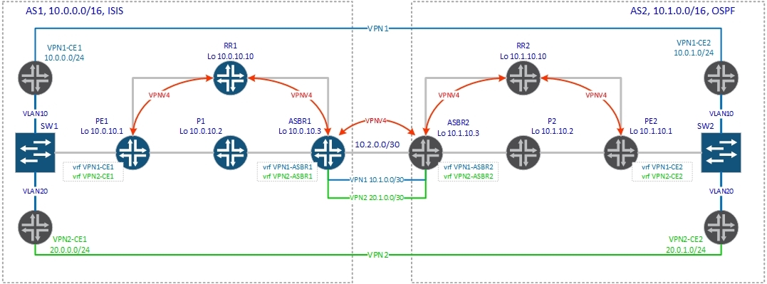
This option, like option A, implies the creation of a separate vrf for each vpn on the ASBRs, as well as the creation of a separate subinterface in each vrf that will be used to transmit client traffic. So far, everything is the same as in the standard option A. The significant difference is that no routing protocol in vrf (on the ASBR) starts up, and the created subinterfaces are used only for traffic forwarding. How will the route be exchanged? For this purpose, as in option B, a single vpnv4 session is created between the ASBRs, through which the vpnv4 routes are transmitted. Actually, we can say that we simultaneously understand both option A and option B between two ASBRs. Let's now move on to the detailed description of the control plane, so that everything falls into place:
1. PE2 generates a vpnv4 route and sends it to the router reflector RR2.
2. Routereflector validates the received route and passes it to its clients. In our case on ASBR2.
3. ASBR2 receives the vpnv4 route and installs it into the routing table of the corresponding vrf, in our case vrf VPN1-ASBR2, according to the configured route-target import.
4. ASBR2 generates a new vpnv4 route, hangs excommunity (route-target) on it, which is indicated on export to vrf VPN1-ASBR2 and sends the route to ASBR1. Next-hop, as with the normal option B, sets the address of the ASBR2 router (the address of the interface, which is the source for this vpnv4 session).
5. ASBR1, accepts this route and according to route-target import, installs this route into the routing table of the corresponding vrf, in our case vrf VPN1-ASBR1, replacing next-hop, according to the one specified in vrf VPN1-ASBR1 (inter-as hybrid next -hop) The replacement is made to the ASBR2 address (ASBR2 (vrf VPN1-ASBR2) ==> ASBR1 (vrf VPN1-ASBR1)).
6. ASBR1 generates a new vpnv4 route, hangs excommunity (route-target) on it, which is indicated on export to vrf VPN1-ASBR1 and sends the route to the router-reflector RR1 (next-hop - loopback ASBR1)
7. RR1 announces route to PE1.
8. PE1, receiving the route from RR1, installs it into the routing table of the corresponding vrf.
The main thing in this option is that vpnv4 routes to ASBR first get into vrf and are already further announced from this vrf, and are announced with the excommunity specified in vrf for export, and it may differ from the excommunity with which this route was originally was announced). Schematically, it looks like this:

That is, the transfer of a vpnv4 route from one AS to another occurs in the following sequence: PE2 ==> RR2 ==> ASBR2 ==> ASBR2 (vrf VPN1-ASBR2) ==> ASBR1 ==> ASBR1 (vrf VPN1-ASBR1) == > RR1 ==> PE1.
So, we will consider all of the above with an example.
Two vrfs are created on PE2:
We will consider signaling route 10.0.1.0/24 of vrf VPN1-CE2.
Below is vpnv4, route generated by PE2:
We see that for PE2 the route is local and for this prefix the generated label is 22.
Now PE2 should send this route to the router. Check:
We announce two routes (10.1.1.2 - this is the loopback of the VPN1-CE2 router, which is received via ospf). Then the route is transmitted to ASBR2:
We have not enabled the no bgp default route-target filter option, but vrf are created on ASBR2:
According to route-target import 2: 100 routes fall into vrf VPN1-ASBR2.
Note: a new command has appeared in the vrf configuration: inter-as-hybrid next-hop. Her appointment will be discussed further.
Check if our route to the 10.0.1.0/24 network is installed in the routing table of vrf VPN1-ASBR2:
Great, there is a route. So far, everything is as in option A. But in option A, then we have to announce pure ip routes from one vrf to another using a routing protocol specially launched in vrf. But in the AV options, routes between ASBRs are transmitted via bgp vpnv4 sessions between ASBRs. Let's see what we announce on the ASBR1 for bgp session between ASBRs:
We announce 4 routes, but they no longer have the original rd. The announcement with PE1 was with rd 2: 1, and now we are announcing routes with rd 2: 10001. That is, the route has been re-generated on ASBR2. For this to work, it is necessary in the bgp session settings between the ASBRs to give the command: inter-as-hybrid. This command indicates that this session is intended to transfer vpnv4 routes for the AB option (in terms of Cisco - the option AB vrf created on the ASBR vrf).
We continue. Check the routes to the network 10.0.1.0/24 on ASBR1:
In the output we have two routes, one with next-hop 10.2.0.2 - this is the original vpnv4 route received from ASBR2; the second one with next-hop 10.1.0.2 (via VPN1-ASBR1) is an already changed route that will be used to send traffic and install into the routing table VPN1-ASBR1.
Please pay attention to the fact that ASBR2 as it should be ASBR-ru in option B generated a label: there is a label on out in the route on ASBR1: “mpls labels in / out 31/19”. But this label will not be used to transmit traffic. This is evident from the route that is imported into the vrf VPN1-ASBR1 routing table: there are no labels in the mpls route: “MPLS label: none” (see output below):
The next-hop replacement was made thanks to the inter-as-hybrid next-hop command on ASBR1:
If this command is not specified, then the route with the original next-hop from the received route from ASBR2 from vpnv4 will be imported into vrf (that is, the next-hop will be the address of ASBR2, which is used as the source for the eBGP session ). In our case on ASBR1 we have the following interfaces:
We need to have vpn1 traffic forwarded through the interface GigabitEthernet3 / 0.10 (respectively, vpn2 - via GigabitEthernet3 / 0.20). Therefore, in the settings of the next-hop vrf, the address is 10.1.0.2 - the GigabitEthernet3 / 0.10 interface on ASBR2, which is located in vrf VPN1-ASBR2:
Moving on. From vrf VPN1-ASBR1, this route should be announced to the router:
I think you have already noticed that this is a new route generated by ASBR1, as here are the routes that ASBR1 received (pay attention to rd):
But the routes, which were announced with ASBR1:
Notice the rd: was 2: 10001, now 1: 10001. Let's see which vrfs are configured on ASBR1:
I think now it is clear that the route was generated by ASBR1.
ASBR1 generated label 31 for this prefix:
Then everything is standard. The route is transferred from RR1 to PE1:
PE1 installs its corresponding vrf routing table:
The picture below shows the process of signaling the vpn tag.

Now let's go to the data plane . Let's trace between CE routers:
And the same for vpn2:
PE1 receives an IP packet from the client router and, according to its routing table, hangs two tags — 31 (vrf tag) and 17 or 16 (transport tag to ASBR1 depending on how PE1 balances traffic):
Judging by the tracing above, PE1 selects the route through P1.
P1, having received a packet with label 17, removes this (top) tag and sends the packet to the Gi1 / 0 interface (link to ASBR1):
ASBR1 processes the packet as a normal PE router - removes the label and sends a clean IP packet to the Gi3 / 0.10 interface:
Having received this packet, ASBR2, works as a PE router, received a packet from the client CE of the router - hangs the vrf (22) tag and transport tag (17 or 19 - again equivalent paths and judging by the trace, the packet goes to RR2):
RR2, as it should be for the transit mpls router on the last but one hop, removes the top label and sends the packet to PE2:
Well, PE2 knows that label 22 indicates that ip lookup needs to be done in vrf VPN1-CE2:
Next, the packet flies to the client CE router. All labels and operations with them are presented in the figure below.

As a result, we got a hybrid of option A and B, in which we can use qos and filter client traffic between ASBRs as in option A, but at the same time we will have to configure vrf for each vpn on ASBR and make a separate interface, but There is no need for a separate routing protocol process in each vrf, which naturally reduces the load on the ASBR, which, as in option B, should support only one vpnv4 session with the neighboring ASBR.
Well, in the end I would like to focus on two important teams:
inter-as-hybrid next-hop in the ip vrf hierarchy - this command is necessary to substitute the next-hop, if left unchecked, the route with next-hop will be imported into vrf to the interface where option B is running.
neighbor 10.2.0.1 inter-as-hybrid - this command indicates that a bgp session is established between peers for exchanging vpnv4 routes for Inter-AS Option AB. This command allows you to first import routes into vrf, and then export routes from this vrf further (changing rd and, if necessary, community).
It is important that both of these options must be enabled, otherwise you will either earn nothing or earn it, but not as it should work.
Currently, there is only an RFC draft AB draft. In this article, we got acquainted with the AB option on the example of its implementation by Cisco. Write in a personal if you find any flaws or think that something needs to be added / described better.
Thank you all for your attention!
Option A.
The meaning of this option is that ASBR-ras raise separate vrf for each client vpn and create a subinterface through which pure ip routes are exchanged and, through these same subinterfaces, client traffic is forwarded. There are no mpls between ASBRs. The interaction between ASBRs occurs as between PE and CE routers.
The disadvantages of this option are more than obvious:
- besides creating vrf on PE routers, it is necessary to create vrf on ASBRs;
')
- for the exchange of routes between ASBRs, it is necessary to raise the routing protocol in each vrf, of course a large number, for example, bgp-sessions do not have a positive effect on the router's performance;
But, not surprisingly, this scheme has advantages:
+ since there is pure ip traffic between ASBR, without mpls, you can implement qos and filtering based on ip header;
+ customer traffic is clearly divided;
+ This option is the most secure of all (for example, if you can raise this option between different providers if you do not want to inject other people's routes into your autonomous system).
But all the same, the disadvantages in this case outweigh the advantages (imagine that you need to throw 50-60 vpn-s - the desire to use the option A immediately disappears). Therefore, being in your own mind, it is unlikely that an engineer would, in the present circumstances, want to raise option A.
Option B.
The meaning of this option is that the ASBR exchange vpnv4 routes. Having received a vpnv4 route from a neighboring AS, the ASBR generates a new label, puts itself (option Ba) next-hop or, without changing the next-hop (option Bb), routes the reflector (or PE routers immediately, depending on your topology), after which all PE routers have the necessary vpnv4 routes.
Advantages of this approach:
+ only one BGP vpnv4 session is needed to transfer routes between autonomous systems, ASBR is not loaded with routing protocols in vrf;
+ since all prefixes are transmitted within one session, this approach has good scalability (in comparison with option A);
+ when you turn on a new client, there is no need to change the configuration to ASBR (except for filters, of course);
Minuses:
- client traffic is transmitted in the general stream with a mpls tag and it is not possible to apply qos or filtering based on the ip header;
- ASBR is loaded in addition to traffic forwarding, and the digestion of a large number of vpnv4 routes;
Option C.
The meaning of this option is that the exchange of vpnv4 routes takes place between the router-reflectors of different autonomous systems via an ebgp-multihop session. The ASBRs, in turn, pass the labeled routes (bgp labeled-unicast) to neighboring autonomous systems to the loopbacks of the router and the PE routers. As a result, using the labels received from the ASBR, PE routers can build end-to-end lsp between themselves, and vrf tags between all PE routers are distributed using router-reflectors.
Advantages of this option:
+ very high scalability
+ does not load ASBR with unnecessary work (in comparison with other options)
But there are also disadvantages:
- as in option B, client traffic between ASBRs goes in a common stream, albeit with two mpls tags, which prevents qos and filtering traffic between ASBRs based on the ip header.
How to combine the possibility of using filters / qos in one approach and at the same time not to burden the ASBR with unnecessary work on maintaining a large number of bgp (ospf, isis, rip) neighbors, and rid engineers of complex configurations on the ASBR?
So today we’ll talk about inter-AS Option AB (D) .
This option, like option A, implies the creation of a separate vrf for each vpn on the ASBRs, as well as the creation of a separate subinterface in each vrf that will be used to transmit client traffic. So far, everything is the same as in the standard option A. The significant difference is that no routing protocol in vrf (on the ASBR) starts up, and the created subinterfaces are used only for traffic forwarding. How will the route be exchanged? For this purpose, as in option B, a single vpnv4 session is created between the ASBRs, through which the vpnv4 routes are transmitted. Actually, we can say that we simultaneously understand both option A and option B between two ASBRs. Let's now move on to the detailed description of the control plane, so that everything falls into place:
1. PE2 generates a vpnv4 route and sends it to the router reflector RR2.
2. Routereflector validates the received route and passes it to its clients. In our case on ASBR2.
3. ASBR2 receives the vpnv4 route and installs it into the routing table of the corresponding vrf, in our case vrf VPN1-ASBR2, according to the configured route-target import.
4. ASBR2 generates a new vpnv4 route, hangs excommunity (route-target) on it, which is indicated on export to vrf VPN1-ASBR2 and sends the route to ASBR1. Next-hop, as with the normal option B, sets the address of the ASBR2 router (the address of the interface, which is the source for this vpnv4 session).
5. ASBR1, accepts this route and according to route-target import, installs this route into the routing table of the corresponding vrf, in our case vrf VPN1-ASBR1, replacing next-hop, according to the one specified in vrf VPN1-ASBR1 (inter-as hybrid next -hop) The replacement is made to the ASBR2 address (ASBR2 (vrf VPN1-ASBR2) ==> ASBR1 (vrf VPN1-ASBR1)).
6. ASBR1 generates a new vpnv4 route, hangs excommunity (route-target) on it, which is indicated on export to vrf VPN1-ASBR1 and sends the route to the router-reflector RR1 (next-hop - loopback ASBR1)
7. RR1 announces route to PE1.
8. PE1, receiving the route from RR1, installs it into the routing table of the corresponding vrf.
The main thing in this option is that vpnv4 routes to ASBR first get into vrf and are already further announced from this vrf, and are announced with the excommunity specified in vrf for export, and it may differ from the excommunity with which this route was originally was announced). Schematically, it looks like this:
That is, the transfer of a vpnv4 route from one AS to another occurs in the following sequence: PE2 ==> RR2 ==> ASBR2 ==> ASBR2 (vrf VPN1-ASBR2) ==> ASBR1 ==> ASBR1 (vrf VPN1-ASBR1) == > RR1 ==> PE1.
So, we will consider all of the above with an example.
Two vrfs are created on PE2:
ip vrf VPN1-CE2 rd 2:1 route-target export 2:100 route-target import 1:100 route-target import 2:100 ! ip vrf VPN2-CE2 rd 2:2 route-target export 2:200 route-target import 1:200 route-target import 2:200 We will consider signaling route 10.0.1.0/24 of vrf VPN1-CE2.
Below is vpnv4, route generated by PE2:
PE2#sh ip bgp vpnv4 rd 2:1 10.0.1.0/24 BGP routing table entry for 2:1:10.0.1.0/24, version 2 Paths: (1 available, best #1, table VPN1-CE2) Advertised to update-groups: 3 Local 0.0.0.0 from 0.0.0.0 (10.1.10.1) Origin incomplete, metric 0, localpref 100, weight 32768, valid, sourced, best Extended Community: RT:2:100 OSPF DOMAIN ID:0x0005:0x000000020200 OSPF RT:0.0.0.0:2:0 OSPF ROUTER ID:10.0.1.1:0 mpls labels in/out IPv4 VRF Aggr:22/nolabel(VPN1-CE2) We see that for PE2 the route is local and for this prefix the generated label is 22.
Now PE2 should send this route to the router. Check:
PE2#show ip bgp vpnv4 rd 2:1 neighbors 10.1.10.10 advertised-routes BGP table version is 13, local router ID is 10.1.10.1 Status codes: s suppressed, d damped, h history, * valid, > best, i - internal, r RIB-failure, S Stale Origin codes: i - IGP, e - EGP, ? - incomplete Originating default network 0.0.0.0 Network Next Hop Metric LocPrf Weight Path Route Distinguisher: 2:1 (default for vrf VPN1-CE2) *> 10.0.1.0/24 0.0.0.0 0 32768 ? *> 10.1.1.2/32 10.0.1.2 2 32768 ? Total number of prefixes 2 We announce two routes (10.1.1.2 - this is the loopback of the VPN1-CE2 router, which is received via ospf). Then the route is transmitted to ASBR2:
RR2#sh ip bgp vpnv4 rd 2:1 neighbors 10.1.10.3 advertised-routes | i 10. BGP table version is 37, local router ID is 10.1.10.10 *>i10.0.1.0/24 10.1.10.1 0 100 0 ? *>i10.1.1.2/32 10.1.10.1 2 100 0 ? ASBR2#sh ip bgp vpnv4 rd 2:1 10.0.1.0/24 BGP routing table entry for 2:1:10.0.1.0/24, version 100 Paths: (1 available, best #1, no table) Not advertised to any peer Local 10.1.10.1 (metric 3) from 10.1.10.10 (10.1.10.10) Origin incomplete, metric 0, localpref 100, valid, internal, best Extended Community: RT:2:100 OSPF DOMAIN ID:0x0005:0x000000020200 OSPF RT:0.0.0.0:2:0 OSPF ROUTER ID:10.0.1.1:0 Originator: 10.1.10.1, Cluster list: 10.1.10.10 mpls labels in/out nolabel/22 We have not enabled the no bgp default route-target filter option, but vrf are created on ASBR2:
ip vrf VPN1-ASBR2 rd 2:10001 route-target export 2:100 route-target import 1:100 route-target import 2:100 inter-as-hybrid next-hop 10.1.0.1 ! ip vrf VPN2-ASBR2 rd 2:10002 route-target export 2:200 route-target import 1:200 route-target import 2:200 inter-as-hybrid next-hop 20.1.0.1 According to route-target import 2: 100 routes fall into vrf VPN1-ASBR2.
Note: a new command has appeared in the vrf configuration: inter-as-hybrid next-hop. Her appointment will be discussed further.
Check if our route to the 10.0.1.0/24 network is installed in the routing table of vrf VPN1-ASBR2:
ASBR2#sh ip route vrf VPN1-ASBR2 10.0.1.0 Routing Table: VPN1-ASBR2 Routing entry for 10.0.1.0/24 Known via "bgp 2", distance 200, metric 0, type internal Last update from 10.1.10.1 00:50:46 ago Routing Descriptor Blocks: * 10.1.10.1 (default), from 10.1.10.10, 00:50:46 ago Route metric is 0, traffic share count is 1 AS Hops 0 MPLS label: 22 MPLS Flags: MPLS Required Great, there is a route. So far, everything is as in option A. But in option A, then we have to announce pure ip routes from one vrf to another using a routing protocol specially launched in vrf. But in the AV options, routes between ASBRs are transmitted via bgp vpnv4 sessions between ASBRs. Let's see what we announce on the ASBR1 for bgp session between ASBRs:
ASBR2#sh ip bgp vpnv4 all neighbors 10.2.0.1 advertised-routes BGP table version is 109, local router ID is 10.1.10.3 Status codes: s suppressed, d damped, h history, * valid, > best, i - internal, r RIB-failure, S Stale Origin codes: i - IGP, e - EGP, ? - incomplete Originating default network 0.0.0.0 Network Next Hop Metric LocPrf Weight Path Route Distinguisher: 2:10001 (default for vrf VPN1-ASBR2) *>i10.0.1.0/24 10.1.10.1 0 100 0 ? *>i10.1.1.2/32 10.1.10.1 2 100 0 ? Route Distinguisher: 2:10002 (default for vrf VPN2-ASBR2) *>i20.0.1.0/24 10.1.10.1 0 100 0 ? *>i20.1.1.2/32 10.1.10.1 2 100 0 ? Total number of prefixes 4 We announce 4 routes, but they no longer have the original rd. The announcement with PE1 was with rd 2: 1, and now we are announcing routes with rd 2: 10001. That is, the route has been re-generated on ASBR2. For this to work, it is necessary in the bgp session settings between the ASBRs to give the command: inter-as-hybrid. This command indicates that this session is intended to transfer vpnv4 routes for the AB option (in terms of Cisco - the option AB vrf created on the ASBR vrf).
ASBR2#sh configuration | b address-family vpnv4 address-family vpnv4 neighbor 10.1.10.10 activate neighbor 10.1.10.10 send-community extended neighbor 10.2.0.1 activate neighbor 10.2.0.1 send-community extended neighbor 10.2.0.1 inter-as-hybrid exit-address-family We continue. Check the routes to the network 10.0.1.0/24 on ASBR1:
ASBR1#sh ip bgp vpnv4 all 10.0.1.0/24 BGP routing table entry for 1:10001:10.0.1.0/24, version 98 Paths: (1 available, best #1, table VPN1-ASBR1) Advertised to update-groups: 1 2, imported path from 2:10001:10.0.1.0/24 10.1.0.2 (via VPN1-ASBR1) from 10.2.0.2 (10.1.10.3) Origin incomplete, localpref 100, valid, external, best Extended Community: RT:2:100 OSPF DOMAIN ID:0x0005:0x000000020200 OSPF RT:0.0.0.0:2:0 OSPF ROUTER ID:10.0.1.1:0 mpls labels in/out 31/19 BGP routing table entry for 2:10001:10.0.1.0/24, version 94 Paths: (1 available, best #1, no table) Not advertised to any peer 2 10.2.0.2 from 10.2.0.2 (10.1.10.3) Origin incomplete, localpref 100, valid, external, best Extended Community: RT:2:100 OSPF DOMAIN ID:0x0005:0x000000020200 OSPF RT:0.0.0.0:2:0 OSPF ROUTER ID:10.0.1.1:0 mpls labels in/out nolabel/19 In the output we have two routes, one with next-hop 10.2.0.2 - this is the original vpnv4 route received from ASBR2; the second one with next-hop 10.1.0.2 (via VPN1-ASBR1) is an already changed route that will be used to send traffic and install into the routing table VPN1-ASBR1.
Please pay attention to the fact that ASBR2 as it should be ASBR-ru in option B generated a label: there is a label on out in the route on ASBR1: “mpls labels in / out 31/19”. But this label will not be used to transmit traffic. This is evident from the route that is imported into the vrf VPN1-ASBR1 routing table: there are no labels in the mpls route: “MPLS label: none” (see output below):
ASBR1#sh ip rou vrf VPN1-ASBR1 10.0.1.0 Routing Table: VPN1-ASBR1 Routing entry for 10.0.1.0/24 Known via "bgp 1", distance 20, metric 0 Tag 2, type external Last update from 10.1.0.2 on GigabitEthernet3/0.10, 01:14:18 ago Routing Descriptor Blocks: * 10.1.0.2, from 10.2.0.2, 01:14:18 ago, via GigabitEthernet3/0.10 Route metric is 0, traffic share count is 1 AS Hops 1 Route tag 2 MPLS label: none The next-hop replacement was made thanks to the inter-as-hybrid next-hop command on ASBR1:
ip vrf VPN1-ASBR1 rd 1:10001 route-target export 1:100 route-target import 1:100 route-target import 2:100 inter-as-hybrid next-hop 10.1.0.2 If this command is not specified, then the route with the original next-hop from the received route from ASBR2 from vpnv4 will be imported into vrf (that is, the next-hop will be the address of ASBR2, which is used as the source for the eBGP session ). In our case on ASBR1 we have the following interfaces:
ASBR1#sh int description | i Gi3 Gi3/0 up up "to ASBR2 | AS2" Gi3/0.2 up up "to ASBR2 | vpnv4 routes only" Gi3/0.10 up up "for VPN1 only" Gi3/0.20 up up "for VPN2 only" ASBR1#sh ip int brief | i 3/0 GigabitEthernet3/0 unassigned YES NVRAM up up GigabitEthernet3/0.2 10.2.0.1 YES NVRAM up up GigabitEthernet3/0.10 10.1.0.1 YES NVRAM up up GigabitEthernet3/0.20 20.1.0.1 YES NVRAM up up We need to have vpn1 traffic forwarded through the interface GigabitEthernet3 / 0.10 (respectively, vpn2 - via GigabitEthernet3 / 0.20). Therefore, in the settings of the next-hop vrf, the address is 10.1.0.2 - the GigabitEthernet3 / 0.10 interface on ASBR2, which is located in vrf VPN1-ASBR2:
ASBR2#sh run int gigabitEthernet 3/0.10 Building configuration... Current configuration : 165 bytes ! interface GigabitEthernet3/0.10 description "for VPN1 forwarding" encapsulation dot1Q 10 ip vrf forwarding VPN1-ASBR2 ip address 10.1.0.2 255.255.255.252 end Moving on. From vrf VPN1-ASBR1, this route should be announced to the router:
ASBR1#sh ip bgp vpnv4 all neighbors 10.0.10.10 advertised-routes BGP table version is 101, local router ID is 10.0.10.3 Status codes: s suppressed, d damped, h history, * valid, > best, i - internal, r RIB-failure, S Stale Origin codes: i - IGP, e - EGP, ? - incomplete Originating default network 0.0.0.0 Network Next Hop Metric LocPrf Weight Path Route Distinguisher: 1:10001 (default for vrf VPN1-ASBR1) *> 10.0.1.0/24 10.1.0.2 0 2 ? *> 10.1.1.2/32 10.1.0.2 0 2 ? Route Distinguisher: 1:10002 (default for vrf VPN2-ASBR1) *> 20.0.1.0/24 20.1.0.2 0 2 ? *> 20.1.1.2/32 20.1.0.2 0 2 ? Total number of prefixes 4 I think you have already noticed that this is a new route generated by ASBR1, as here are the routes that ASBR1 received (pay attention to rd):
Route Distinguisher: 2:10001 (default for vrf VPN1-ASBR2) *>i10.0.1.0/24 10.1.10.1 0 100 0 ? *>i10.1.1.2/32 10.1.10.1 2 100 0 ? But the routes, which were announced with ASBR1:
Route Distinguisher: 1:10001 (default for vrf VPN1-ASBR1) *> 10.0.1.0/24 10.1.0.2 0 2 ? *> 10.1.1.2/32 10.1.0.2 0 2 ? Notice the rd: was 2: 10001, now 1: 10001. Let's see which vrfs are configured on ASBR1:
ip vrf VPN1-ASBR1 rd 1:10001 route-target export 1:100 route-target import 1:100 route-target import 2:100 inter-as-hybrid next-hop 10.1.0.2 ! ip vrf VPN2-ASBR1 rd 1:10002 route-target export 1:200 route-target import 1:200 route-target import 2:200 inter-as-hybrid next-hop 20.1.0.2 I think now it is clear that the route was generated by ASBR1.
ASBR1 generated label 31 for this prefix:
RR1#sh ip bgp vpnv4 all 10.0.1.0/24 BGP routing table entry for 1:10001:10.0.1.0/24, version 38 Paths: (1 available, best #1, no table) Advertised to update-groups: 1 2, (Received from a RR-client) 10.0.10.3 (metric 20) from 10.0.10.3 (10.0.10.3) Origin incomplete, metric 0, localpref 100, valid, internal, best Extended Community: RT:1:100 OSPF DOMAIN ID:0x0005:0x000000020200 OSPF RT:0.0.0.0:2:0 OSPF ROUTER ID:10.0.1.1:0 mpls labels in/out nolabel/31 Then everything is standard. The route is transferred from RR1 to PE1:
RR1#sh ip bgp vpnv4 rd 1:10001 neighbors 10.0.10.1 advertised-routes BGP table version is 41, local router ID is 10.0.10.10 Status codes: s suppressed, d damped, h history, * valid, > best, i - internal, r RIB-failure, S Stale Origin codes: i - IGP, e - EGP, ? - incomplete Originating default network 0.0.0.0 Network Next Hop Metric LocPrf Weight Path Route Distinguisher: 1:10001 *>i10.0.1.0/24 10.0.10.3 0 100 0 2 ? *>i10.1.1.2/32 10.0.10.3 0 100 0 2 ? Total number of prefixes 2 PE1 installs its corresponding vrf routing table:
PE1#sh ip route vrf VPN1-CE1 10.0.1.0 Routing Table: VPN1-CE1 Routing entry for 10.0.1.0/24 Known via "bgp 1", distance 200, metric 0 Tag 2, type internal Redistributing via ospf 1 Advertised by ospf 1 subnets Last update from 10.0.10.3 01:45:25 ago Routing Descriptor Blocks: * 10.0.10.3 (default), from 10.0.10.10, 01:45:25 ago Route metric is 0, traffic share count is 1 AS Hops 1 Route tag 2 MPLS label: 31 MPLS Flags: MPLS Required The picture below shows the process of signaling the vpn tag.
Now let's go to the data plane . Let's trace between CE routers:
CE1-VPN1#ping 10.0.1.2 Type escape sequence to abort. Sending 5, 100-byte ICMP Echos to 10.0.1.2, timeout is 2 seconds: !!!!! Success rate is 100 percent (5/5), round-trip min/avg/max = 72/101/144 ms CE1-VPN1#traceroute 10.0.1.2 Type escape sequence to abort. Tracing the route to 10.0.1.2 1 10.0.0.1 32 msec 12 msec 8 msec 2 10.0.2.2 [MPLS: Labels 17/31 Exp 0] 48 msec 44 msec 48 msec 3 10.1.0.1 [MPLS: Label 31 Exp 0] 44 msec 40 msec 12 msec 4 10.1.0.2 60 msec 48 msec 44 msec 5 10.1.0.2 [MPLS: Labels 17/22 Exp 0] 72 msec 88 msec 68 msec 6 10.0.1.1 80 msec 40 msec 56 msec 7 10.0.1.2 100 msec 84 msec 80 msec And the same for vpn2:
VPN2-CE1#ping 20.0.1.2 Type escape sequence to abort. Sending 5, 100-byte ICMP Echos to 20.0.1.2, timeout is 2 seconds: !!!!! Success rate is 100 percent (5/5), round-trip min/avg/max = 92/120/144 ms VPN2-CE1#traceroute 20.0.1.2 Type escape sequence to abort. Tracing the route to 20.0.1.2 1 20.0.0.1 64 msec 16 msec 16 msec 2 10.0.0.2 [MPLS: Labels 16/32 Exp 0] 44 msec 40 msec 40 msec 3 20.1.0.1 [MPLS: Label 32 Exp 0] 12 msec 28 msec 24 msec 4 20.1.0.2 52 msec 44 msec 40 msec 5 10.1.0.2 [MPLS: Labels 17/23 Exp 0] 40 msec 48 msec 64 msec 6 20.0.1.1 60 msec 48 msec 84 msec 7 20.0.1.2 76 msec 72 msec 76 msec PE1 receives an IP packet from the client router and, according to its routing table, hangs two tags — 31 (vrf tag) and 17 or 16 (transport tag to ASBR1 depending on how PE1 balances traffic):
PE1#sh ip route vrf VPN1-CE1 10.0.1.0 Routing Table: VPN1-CE1 Routing entry for 10.0.1.0/24 Known via "bgp 1", distance 200, metric 0 Tag 2, type internal Redistributing via ospf 1 Advertised by ospf 1 subnets Last update from 10.0.10.3 01:45:25 ago Routing Descriptor Blocks: * 10.0.10.3 (default), from 10.0.10.10, 01:45:25 ago Route metric is 0, traffic share count is 1 AS Hops 1 Route tag 2 MPLS label: 31 MPLS Flags: MPLS Required PE1#sh mpls forwarding-table 10.0.10.3 Local Outgoing Prefix Bytes Label Outgoing Next Hop Label Label or Tunnel Id Switched interface 18 16 10.0.10.3/32 0 Gi1/0 10.0.0.2 17 10.0.10.3/32 0 Gi2/0 10.0.2.2 Judging by the tracing above, PE1 selects the route through P1.
P1, having received a packet with label 17, removes this (top) tag and sends the packet to the Gi1 / 0 interface (link to ASBR1):
P1#sh mpls forwarding-table labels 17 Local Outgoing Prefix Bytes Label Outgoing Next Hop Label Label or Tunnel Id Switched interface 17 Pop Label 10.0.10.3/32 11590 Gi1/0 10.0.3.1 ASBR1 processes the packet as a normal PE router - removes the label and sends a clean IP packet to the Gi3 / 0.10 interface:
ASBR1#sh mpls forwarding-table labels 31 Local Outgoing Prefix Bytes Label Outgoing Next Hop Label Label or Tunnel Id Switched interface 31 No Label 10.0.1.0/24[V] 1712 Gi3/0.10 10.1.0.2 Having received this packet, ASBR2, works as a PE router, received a packet from the client CE of the router - hangs the vrf (22) tag and transport tag (17 or 19 - again equivalent paths and judging by the trace, the packet goes to RR2):
ASBR2# sh ip route vrf VPN1-ASBR2 10.0.1.0 Routing Table: VPN1-ASBR2 Routing entry for 10.0.1.0/24 Known via "bgp 2", distance 200, metric 0, type internal Last update from 10.1.10.1 01:51:32 ago Routing Descriptor Blocks: * 10.1.10.1 (default), from 10.1.10.10, 01:51:32 ago Route metric is 0, traffic share count is 1 AS Hops 0 MPLS label: 22 MPLS Flags: MPLS Required ASBR2#sh mpls forwarding-table 10.1.10.1 Local Outgoing Prefix Bytes Label Outgoing Next Hop Label Label or Tunnel Id Switched interface 23 17 10.1.10.1/32 0 Gi1/0 10.1.0.2 19 10.1.10.1/32 0 Gi2/0 10.1.2.2 RR2, as it should be for the transit mpls router on the last but one hop, removes the top label and sends the packet to PE2:
RR2#sh mpls forwarding-table labels 17 Local Outgoing Prefix Bytes Label Outgoing Next Hop Label Label or Tunnel Id Switched interface 17 Pop Label 10.1.10.1/32 7242 Gi2/0 10.1.1.1 Well, PE2 knows that label 22 indicates that ip lookup needs to be done in vrf VPN1-CE2:
PE2#show mpls forwarding-table labels 22 Local Outgoing Prefix Bytes Label Outgoing Next Hop Label Label or Tunnel Id Switched interface 22 Pop Label IPv4 VRF[V] 8150 aggregate/VPN1-CE2 Next, the packet flies to the client CE router. All labels and operations with them are presented in the figure below.
As a result, we got a hybrid of option A and B, in which we can use qos and filter client traffic between ASBRs as in option A, but at the same time we will have to configure vrf for each vpn on ASBR and make a separate interface, but There is no need for a separate routing protocol process in each vrf, which naturally reduces the load on the ASBR, which, as in option B, should support only one vpnv4 session with the neighboring ASBR.
Well, in the end I would like to focus on two important teams:
inter-as-hybrid next-hop in the ip vrf hierarchy - this command is necessary to substitute the next-hop, if left unchecked, the route with next-hop will be imported into vrf to the interface where option B is running.
neighbor 10.2.0.1 inter-as-hybrid - this command indicates that a bgp session is established between peers for exchanging vpnv4 routes for Inter-AS Option AB. This command allows you to first import routes into vrf, and then export routes from this vrf further (changing rd and, if necessary, community).
It is important that both of these options must be enabled, otherwise you will either earn nothing or earn it, but not as it should work.
Currently, there is only an RFC draft AB draft. In this article, we got acquainted with the AB option on the example of its implementation by Cisco. Write in a personal if you find any flaws or think that something needs to be added / described better.
Thank you all for your attention!
Source: https://habr.com/ru/post/303386/
All Articles