CD Changer Control Protocol
We continue the begun . This time I will talk about what is contained in the payload of the I / K-bus frame, briefly about the device of the infotainment system BMW e38, e39, e46, e53, and consider in more detail how the protocol works on the example of a CD changer.
Logically, the data link layer contains higher level protocols in its data. This happens in I / K-bus, only there are no network and transport protocols like TCP / IP in it. Nowhere is the network address information in the frame, but interworking is possible. It is performed by means of a gateway, which is made in the instrument cluster block. The essence of the gateway is simple - it knows in which network this or that block is located, accordingly it sends the frame to another network if the sender and the receiver are in different ones. Thus, interconnection on the data link layer is provided as if it is a single network segment. The figure below illustrates the connection of networks in a common system of interaction between control units.
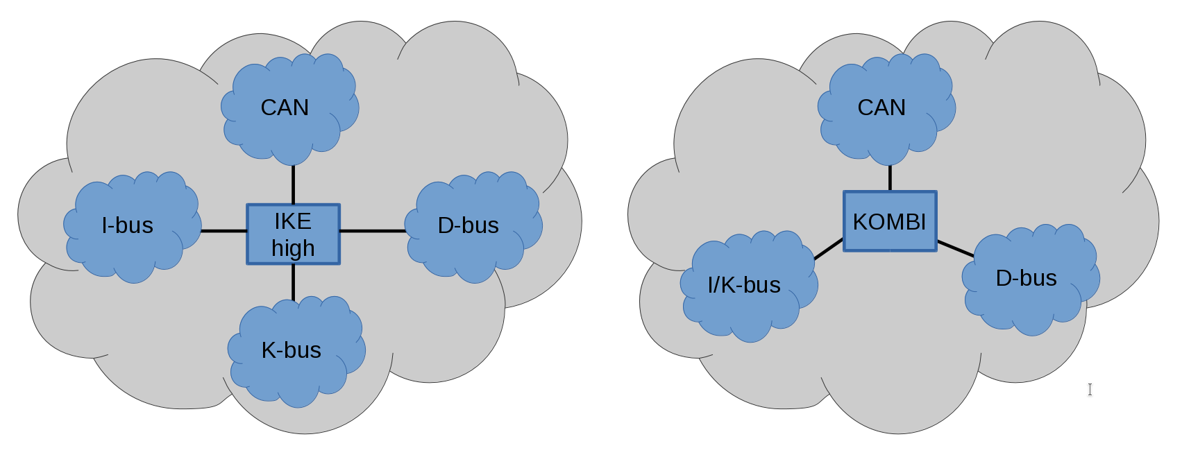
It should be clarified that the left scheme is valid for the e38 and e39, e53 bodies with the instrument cluster of increased functionality (IKE high). In the e39, e53 with the base of the instrument cluster (KOMBI), as well as in the e46, the I-bus and K-bus are physically combined into one.
')
D-bus is a diagnostic bus (k-line). It connects diagnostic equipment. This bus does not have a physical connection to all control units, but through the gateway in IKE / KOMBI the task of interaction is fully provided. For example, the navigation unit is only connected to the I-bus, but with the help of service / diagnostic equipment, we can read service information, errors, and perform coding.
What is contained in the I / K-bus frame payload, I will call the application layer protocol. Basically, it consists of two parts. MSG ID - message identifier, takes one character. MSG DATA - information that supplements the message, may be absent altogether or take up to 32 characters. The following image shows what it looks like:

Since the symbol consists of 8 bits, it turns out possible command variations (CMD ID) 256. Quite a lot, probably even with a margin, and I know not all. But on some key I will focus.
The message with the identifier MSG ID = 01 is a request for the device status. Before interacting with any device, you must make sure that it is present and in good condition. This command is sent to the device that you want to verify. In this case, the MSG DATA field is not filled. So that information on the status of devices is relevant all the time, the command is repeated periodically. Consider this type of message on the example of the frame 68 03 18 01 72 (hereinafter, the contents of the frame will be denoted by numbers in hexadecimal). The frame is sent from the radio (device identifier 68 ) to the CD changer ( 18 ) with a status request (message identifier MSG ID = 01 ). The CD changer, if it exists and is healthy, responds with a message confirming the readiness status (MSG ID = 02 ). The complete fragment of the response frame 18 04 FF 02 00 E1 . The answer is broadcast to everyone in the local network, as the address of the recipient is FF . Here, in addition to the message identifier, additional data is transmitted - MSG DATA = 00 . If the data value is 01 , then this means that the device has just turned on and this is its first readiness message. This type of dialogue is observed between many control units.
You can control the playback of music tracks, radio stations or change the volume level from the steering wheel or from the center console. These controls transmit information to the radio via the same I-bus. Messages volume control is identified by the number 32 , and the data contains control information. The following is the structure of this message.

The data consists of one byte, in which the blue bit is responsible for the direction of the level change: 0 - subtract, 1 - add. And the green bits show the strength of the relative change from 1 to 15 discrete levels. For example, the frame sent when the “+” key is pressed on the steering wheel looks like this 50 04 68 32 11 1F . This message causes the radio to increase the volume by 1 discrete level. If the clock on the center console is turned sharply clockwise, a frame will be sent to the bus C0 04 68 32 91 0F . Here, the multi-information display reports the requirement to increase the volume by 9 discrete levels.
There are three types of message for button control: the button is pressed, the button is held for a long time and the button is released. In the message data, except for the button state, its identifier is transmitted. For example, a message with MSG ID = 3B means that information is transmitted on the change in the state of the buttons on the steering wheel, which are responsible for controlling the radio receiver and telephone. The MSG DATA consists of one character and contains information about the affected button.

In bits of blue color the button is designated. If this is the 0th bit, then there was an impact on the "search up" button. If the 1st bit, then the button "R / T". If the 3rd bit, then the "search down" button. In the green bit area, the state of the button is indicated. If all bits are 0, then this means that the button is pressed. If the 4th bit is 1, then there was a long button hold. If 5-bit is 1, then the button has been released. Consider the situation when we switch the music track to the next when you press a button on the steering wheel. Two frames will be sent to the bus with a small interval: 50 04 68 3B 01 06 and 50 04 68 3B 21 26 . The first frame reports that the “search up” button was pressed. The second reports that the search up button has been released.
For push-button controls on the center console, be it a multi-information display or an on-board monitor, the approach is the same — information about the button's identifier and its state is transmitted. But the message structure is different.
Now we will consider in general how the infotainment system is arranged on e38, e39, e53 cars. Namely, that part of it that is responsible for playing music and radio. In the figure below I have schematically represented the device of this part of the system.

The central role here is taken by the radio (RAD). The fact is that in addition to the functions of receiving radio stations, this unit performs the functions of an amplifier. If the car is not equipped with an on-board monitor, then a cassette or CD player is located in the case of the radio. In this embodiment, it is located in the center console. If the car is equipped with an on-board monitor, the radio is located in the luggage compartment and an audio input for the cassette player is upgraded. The cassette player is mounted in the on-board monitor.
The speaker system can be in three versions: a simple stereo system, Hi-Fi or Top Hi-Fi. In the first case, the radio is directly connected to the speakers. In the Hi-Fi speaker system, the speakers are larger and they are connected to the radio through an additional amplifier. Such an amplifier, in addition to increasing the power of the audio signal, performs the functions of active equalization for car acoustics and splits the sound into ranges for the respective speakers. The top hi-fi system is even cooler. In addition to all of the above, it has a subwoofer, and the silica gel performs equalization depending on the speed of the car, thereby compensating for the noise of the cabin. The system is also supplemented with surround sound effect.
Information on the selected playback source, track number, radio station frequency, etc., as well as management is performed on the center console via the on-board monitor or multi-information display or something else. In order not to be distracted from driving, audio control can be performed on the multifunction steering wheel (MFL) mentioned above.
The CD changer (CDC) is designed as an addition to the radio. The exchange of control commands and answers is made only between the radio and the CD changer. This is done on the I-bus, like wine in the diagram. The audio signal in analog form is transmitted to the line input of the radio receiver, where it is amplified and fed further to the speaker system. If the top hi-fi speaker system, the signal from the CDC is fed directly to the amplifier in digital form.
Now let's take a closer look at the dialogue between the CD changer and the radio on the I / K-bus. As described earlier, the radio periodically sends requests for the status of the CD changer. If this is present in the car and it is in good condition, then a presence response will be immediately sent to the bus. Having received the answer, the radio receiver forms an additional playback mode in the menu on the central console, in which the source is the CD changer. The driver needs only to press the corresponding button so that the radio starts playing from the CD changer, gets information about the loaded CD, track number and displays this information on the center console.
The CD changer playback control is performed by a message with the MSG ID = 38 . The message structure is as follows:

As you can see, the message is simple in structure and contains two key parameters: CMD and ARG. The code of the required playback mode is transmitted to CMD, and additional data is transmitted to ARG. For clarity and ease of understanding, below is a table that summarizes the well-known commands to me:

Thus, the control of the CD changer is performed, and the latter, in turn, supports the feedback with messages with the identifier 39:
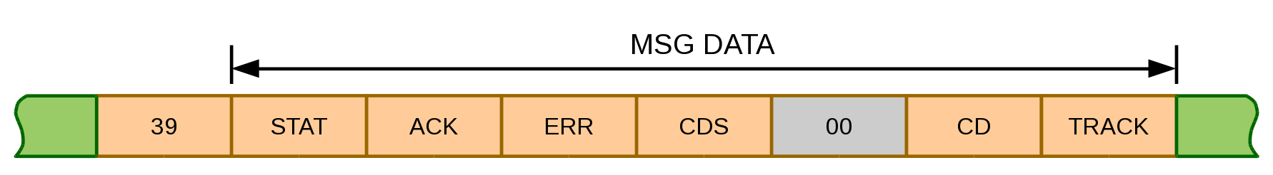
In this message, the status of the CD changer and its playback mode are transmitted. In more detail about each character of the message in the following table:
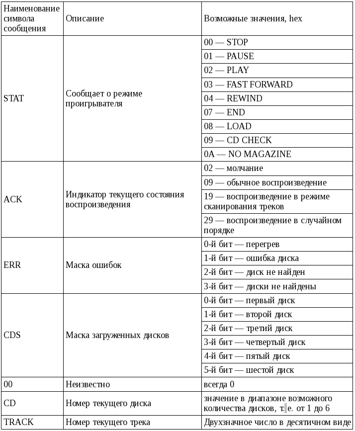
It should be noted that there are control commands from the radio receiver, to which the CD changer should send an immediate response, as confirmation of the acceptance of the command, otherwise the commands will be sent over a 500 ms timeout. Such commands include: “start playback”, “stop playback”, “rewind”, “random track selection mode” and “track scanning mode”. Having received a command with the corresponding CMD identifier, the CD changer changes the status indicator to the required request and sends a message to the radio receiver. In the case of the “rewind” command, the indicator remains in the simple playback mode, only the status changes to “FAST FORWARD” or “REWIND”. The radio receiver calms down, that the command is accepted successfully and ceases to bomb by repeated messages.
Next, I want to give an I / K-bus traffic log, where three devices are connected to the bus: a multi-information display, a radio receiver, and a software changer for the CD changer. I gathered this simple network on my desk to analyze the interaction of control units and debug a software CD changer.

The color here highlights the CD changer control messages and responses.
Summing up, I want to say that by applying this protocol on the simplest hardware and software solution, you can “legally” penetrate into the regular infotainment system of the car. As the simplest example, you can create your own media player that is functional by modern standards and that will receive control commands from the steering wheel, center console and produce sound using a standard speaker system.
Sources used:
Logically, the data link layer contains higher level protocols in its data. This happens in I / K-bus, only there are no network and transport protocols like TCP / IP in it. Nowhere is the network address information in the frame, but interworking is possible. It is performed by means of a gateway, which is made in the instrument cluster block. The essence of the gateway is simple - it knows in which network this or that block is located, accordingly it sends the frame to another network if the sender and the receiver are in different ones. Thus, interconnection on the data link layer is provided as if it is a single network segment. The figure below illustrates the connection of networks in a common system of interaction between control units.
It should be clarified that the left scheme is valid for the e38 and e39, e53 bodies with the instrument cluster of increased functionality (IKE high). In the e39, e53 with the base of the instrument cluster (KOMBI), as well as in the e46, the I-bus and K-bus are physically combined into one.
')
D-bus is a diagnostic bus (k-line). It connects diagnostic equipment. This bus does not have a physical connection to all control units, but through the gateway in IKE / KOMBI the task of interaction is fully provided. For example, the navigation unit is only connected to the I-bus, but with the help of service / diagnostic equipment, we can read service information, errors, and perform coding.
What is contained in the I / K-bus frame payload, I will call the application layer protocol. Basically, it consists of two parts. MSG ID - message identifier, takes one character. MSG DATA - information that supplements the message, may be absent altogether or take up to 32 characters. The following image shows what it looks like:
Since the symbol consists of 8 bits, it turns out possible command variations (CMD ID) 256. Quite a lot, probably even with a margin, and I know not all. But on some key I will focus.
The message with the identifier MSG ID = 01 is a request for the device status. Before interacting with any device, you must make sure that it is present and in good condition. This command is sent to the device that you want to verify. In this case, the MSG DATA field is not filled. So that information on the status of devices is relevant all the time, the command is repeated periodically. Consider this type of message on the example of the frame 68 03 18 01 72 (hereinafter, the contents of the frame will be denoted by numbers in hexadecimal). The frame is sent from the radio (device identifier 68 ) to the CD changer ( 18 ) with a status request (message identifier MSG ID = 01 ). The CD changer, if it exists and is healthy, responds with a message confirming the readiness status (MSG ID = 02 ). The complete fragment of the response frame 18 04 FF 02 00 E1 . The answer is broadcast to everyone in the local network, as the address of the recipient is FF . Here, in addition to the message identifier, additional data is transmitted - MSG DATA = 00 . If the data value is 01 , then this means that the device has just turned on and this is its first readiness message. This type of dialogue is observed between many control units.
You can control the playback of music tracks, radio stations or change the volume level from the steering wheel or from the center console. These controls transmit information to the radio via the same I-bus. Messages volume control is identified by the number 32 , and the data contains control information. The following is the structure of this message.
The data consists of one byte, in which the blue bit is responsible for the direction of the level change: 0 - subtract, 1 - add. And the green bits show the strength of the relative change from 1 to 15 discrete levels. For example, the frame sent when the “+” key is pressed on the steering wheel looks like this 50 04 68 32 11 1F . This message causes the radio to increase the volume by 1 discrete level. If the clock on the center console is turned sharply clockwise, a frame will be sent to the bus C0 04 68 32 91 0F . Here, the multi-information display reports the requirement to increase the volume by 9 discrete levels.
There are three types of message for button control: the button is pressed, the button is held for a long time and the button is released. In the message data, except for the button state, its identifier is transmitted. For example, a message with MSG ID = 3B means that information is transmitted on the change in the state of the buttons on the steering wheel, which are responsible for controlling the radio receiver and telephone. The MSG DATA consists of one character and contains information about the affected button.
In bits of blue color the button is designated. If this is the 0th bit, then there was an impact on the "search up" button. If the 1st bit, then the button "R / T". If the 3rd bit, then the "search down" button. In the green bit area, the state of the button is indicated. If all bits are 0, then this means that the button is pressed. If the 4th bit is 1, then there was a long button hold. If 5-bit is 1, then the button has been released. Consider the situation when we switch the music track to the next when you press a button on the steering wheel. Two frames will be sent to the bus with a small interval: 50 04 68 3B 01 06 and 50 04 68 3B 21 26 . The first frame reports that the “search up” button was pressed. The second reports that the search up button has been released.
For push-button controls on the center console, be it a multi-information display or an on-board monitor, the approach is the same — information about the button's identifier and its state is transmitted. But the message structure is different.
Now we will consider in general how the infotainment system is arranged on e38, e39, e53 cars. Namely, that part of it that is responsible for playing music and radio. In the figure below I have schematically represented the device of this part of the system.
The central role here is taken by the radio (RAD). The fact is that in addition to the functions of receiving radio stations, this unit performs the functions of an amplifier. If the car is not equipped with an on-board monitor, then a cassette or CD player is located in the case of the radio. In this embodiment, it is located in the center console. If the car is equipped with an on-board monitor, the radio is located in the luggage compartment and an audio input for the cassette player is upgraded. The cassette player is mounted in the on-board monitor.
The speaker system can be in three versions: a simple stereo system, Hi-Fi or Top Hi-Fi. In the first case, the radio is directly connected to the speakers. In the Hi-Fi speaker system, the speakers are larger and they are connected to the radio through an additional amplifier. Such an amplifier, in addition to increasing the power of the audio signal, performs the functions of active equalization for car acoustics and splits the sound into ranges for the respective speakers. The top hi-fi system is even cooler. In addition to all of the above, it has a subwoofer, and the silica gel performs equalization depending on the speed of the car, thereby compensating for the noise of the cabin. The system is also supplemented with surround sound effect.
Information on the selected playback source, track number, radio station frequency, etc., as well as management is performed on the center console via the on-board monitor or multi-information display or something else. In order not to be distracted from driving, audio control can be performed on the multifunction steering wheel (MFL) mentioned above.
The CD changer (CDC) is designed as an addition to the radio. The exchange of control commands and answers is made only between the radio and the CD changer. This is done on the I-bus, like wine in the diagram. The audio signal in analog form is transmitted to the line input of the radio receiver, where it is amplified and fed further to the speaker system. If the top hi-fi speaker system, the signal from the CDC is fed directly to the amplifier in digital form.
Now let's take a closer look at the dialogue between the CD changer and the radio on the I / K-bus. As described earlier, the radio periodically sends requests for the status of the CD changer. If this is present in the car and it is in good condition, then a presence response will be immediately sent to the bus. Having received the answer, the radio receiver forms an additional playback mode in the menu on the central console, in which the source is the CD changer. The driver needs only to press the corresponding button so that the radio starts playing from the CD changer, gets information about the loaded CD, track number and displays this information on the center console.
The CD changer playback control is performed by a message with the MSG ID = 38 . The message structure is as follows:
As you can see, the message is simple in structure and contains two key parameters: CMD and ARG. The code of the required playback mode is transmitted to CMD, and additional data is transmitted to ARG. For clarity and ease of understanding, below is a table that summarizes the well-known commands to me:
Thus, the control of the CD changer is performed, and the latter, in turn, supports the feedback with messages with the identifier 39:
In this message, the status of the CD changer and its playback mode are transmitted. In more detail about each character of the message in the following table:
It should be noted that there are control commands from the radio receiver, to which the CD changer should send an immediate response, as confirmation of the acceptance of the command, otherwise the commands will be sent over a 500 ms timeout. Such commands include: “start playback”, “stop playback”, “rewind”, “random track selection mode” and “track scanning mode”. Having received a command with the corresponding CMD identifier, the CD changer changes the status indicator to the required request and sends a message to the radio receiver. In the case of the “rewind” command, the indicator remains in the simple playback mode, only the status changes to “FAST FORWARD” or “REWIND”. The radio receiver calms down, that the command is accepted successfully and ceases to bomb by repeated messages.
Next, I want to give an I / K-bus traffic log, where three devices are connected to the bus: a multi-information display, a radio receiver, and a software changer for the CD changer. I gathered this simple network on my desk to analyze the interaction of control units and debug a software CD changer.
The color here highlights the CD changer control messages and responses.
- Yellow is a switch to the previous track.
- Green - on and off rewind
- Blue - turn on and off the mode of playing tracks in random order.
Summing up, I want to say that by applying this protocol on the simplest hardware and software solution, you can “legally” penetrate into the regular infotainment system of the car. As the simplest example, you can create your own media player that is functional by modern standards and that will receive control commands from the steering wheel, center console and produce sound using a standard speaker system.
Sources used:
- Bus System Troubleshooting, 2001
- I-BUS Inside, Franck Touanen, 2002
Source: https://habr.com/ru/post/303144/
All Articles