RDS, how does it work? We get down to the lowest level of the OSI model
With the RDS system (Radio Data System) at least once came across anyone who saw in the car radio the name of a station like "Road Radio". In addition to the title, additional data may be displayed - the name of the song being played, temperature, broadcast frequency, etc.

But how does this work? Since my hobby is radio and digital signal processing, which was interesting to understand. As it turned out, there is practically no complete information about RDS in RuNet (and in English too sparsely), I hope this publication will fill this gap.
Continuation under the cut (carefully many pictures).
FM radio stations have been around for quite a while. But over time, it became clear that, in addition to sound, there was not enough textual information - the name of the station, track, performer of the song. It was possible to add such an opportunity only in one way - in addition to sound, to transmit an additional digital channel. Moreover, to transmit so that on the one hand, the data were easy to decode (the computational capabilities of the chip in the radio receiver are rather limited), on the other hand, so as not to violate compatibility with existing receivers. The problem was solved, so the RDS standard, adopted in the 1990s, appeared.
')
The range of modern FM-station looks like this:
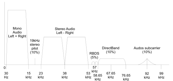
In the picture you can see (from left to right) 4 main components.
- Sound in the format of "mono" (L + R). It was probably left for compatibility with old receivers (it is interesting to observe how in such standards different technologies “overlap” each other to ensure backward compatibility).
- Pilot-tone 19KHz. It is used to decode a stereo signal, for which the frequency of the pilot tone is multiplied by 2, and the stereo channels are separated with respect to the received 38KHz frequency.
- Stereo sound, second channel (LR), located in the picture symmetrically relative to 38KHz.
- The RDS channel, which is transmitted to the 3rd harmonic of the pilot tone, its frequency is 19 * 3 = 57KHz, respectively. We will deal with them.
In order to decode a signal, you first need to understand how it is formed, and there are quite a few “pitfalls” here. The main document describing RDS is “EUROPEAN STANDARD EN 50067”, which we will study.
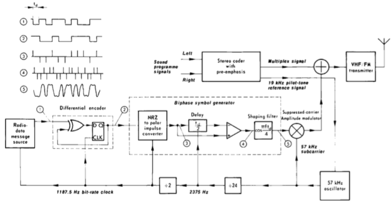
The RDS coder, according to the standard, looks like this:
 "
"
As you can see, the signal in the encoder goes through 5 stages:
1) The original bitstream. To receive it, RDS messages are first encoded into 16-bit packets, then a 10-bit checksum block with error correction is added to them, resulting in 26-bit blocks, which are sent to the encoder. It would seem, we take and send? Everything is more complicated.
2) The bitstream is converted using differential encoding in the following table:
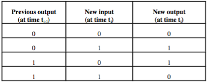
The unit encodes a bit change, the absence of a change is encoded with a zero. This is necessary for a simple purpose - the resulting code is independent to inversion. We may not know what to count “0” and what to count “1”, this coding eliminates this gap.
Consider a simple example, let the transmitted message be 0010100. We encode it according to this table, we get 0011000.
Another table is used for decoding:
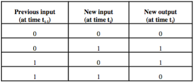
Using it, we get the original message 010100. The meaning of the action is that if the original message is inverted (ie, 1100111), then by decoding it, we still get the same result.
Now take the signal and send? Not yet, everything is more complicated.
3) In the previous step, we received a bit signal, but the problem is that this signal may well have a form like 011000000000011. An electromagnetic wave of this “form” will be badly transmitted and decoded. It is necessary to receive a signal as close as possible to the “classical” sinusoid of the desired frequency. For this, the so-called “biphasic coding” is used (the name “Manchester coding” is often found in Russian-language literature).
Algorithmically, it is written quite simply:
0 -> 01
1 -> 10
With it, the above signal 011000000000011 will be represented as 0110100101010101010101011010, as you can see, we have got rid of the long identical sequences.
The signal shown as number “5” in the encoder scheme is actually our bits after Manchester coding, only the encoder was considered hardware in the standard. It works as follows:
- The bitstream turns into a sequence of short pulses (the number “3” in the picture)
- Manchester coding is performed by delaying the signal by the period floor and adding it with the opposite sign (digit “4”).
- The received signal in the form of "bursts" of positive and negative pulses, is fed to the low-pass filter (low pass filter), which highlights the envelope shown under the number "5".
Now, can the signal be transmitted? Yes you can. But not at once. The original frequency of the digital RDS signal is 1187.5 Hz, which is too small. The received signal is multiplied by another signal with a frequency of 57KHz, which transfers it to a given frequency, we recall the cosine cosine multiplication formula:
The received signal has just the 57KHz frequency we need, it is summed with the “main” (sound) signal, which is broadcast on the air. As you can see from the top picture, adding the 57KHz frequency does not affect the audio channels, and therefore does not add any distortion even to non-supporting RDS receivers.
Now, having understood how the signal is received, we can proceed to demodulate the signal from a real FM station. You need an SDR receiver for this, I used HackRF, but a much cheaper RTL-SDR is suitable, which you can buy for $ 10 with free delivery on eBay.
Since the original signal is frequency-modulated, we must first receive it in demodulated form. In order not to write another FM decoder, let's use the GNU Radio package. Run the GNU Radio Companion and build the circuit, as shown in the figure.
We are going to receive an FM station at a frequency of 100.4 MHz, for this we tune the receiver to 99 MHz, and programmatically “shift” the signal up through the frequency by 1.4 MHz, multiplying it by a signal with such a frequency. This is done because the SDR receiver has a peak at zero frequency relative to the center, and we cannot tune in immediately to the station.
Run the "scheme", and see the picture asin the textbook at the beginning of the article.
You can clearly see the pilot tone at 19KHz, the stereo signal at 38KHz and 2 peaks of the RDS signal around 57KHz.
The next step is to select the pilot tone and the RDS signal. To do this, use a bandpass filter at the appropriate frequency.
We start the received scheme, and we see result, as in any "textbook" according to the description of RDS.
The pilot tone with a frequency of 19 KHz and the 57 KHz signal modulating a lower frequency signal with a frequency of 1187.5 Hz are clearly visible.
To obtain the low-frequency signal requires 2 steps:
3.1) Reception of the 57KHz signal (3rd harmonic of the pilot tone).
We have a 19KHz signal allocated by the filter, but how to get 57KHz from it? To do this, we recall school math, the sine cube formula:
As it is easy to see, the sine cube contains 2 components: sin (a) and sin (3 * a). Since we work with “analog” blocks, take in GNU Radio 2 blocks - a multiplier, and a high-pass filter. Removing sin (a) filter at 38KHz, we get the desired 57KHz.
The finished result can be seen on the oscillogram:
3.2) Reverse frequency transfer
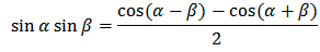
When coding, the signal was transferred from the frequency 1187.5 Hz up, multiplying by 57 kHz. Now we perform the inverse operation, transfer the signal "down". To do this, once again multiply it by the 57KHz signal. According to the formula of the product of sines (the school program is a useful thing) we get 2 components - sums and differences of frequency. We need exactly the difference, the amount we discard using a low pass filter.
All this is done by adding blocks to GNU Radio, the final result is shown in the picture:
A green “model” signal with a frequency of 1187.5 Hz is shown in green to see that the conversion is correct.
The principle of this part is easiest to illustrate with a picture from a standard (“biphase symbol decoder” block).
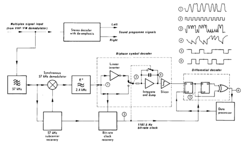
Biphasic demodulation consists of 2 parts.
- "Reverse" signal inverter. This is needed to return from the biphasic coding, which was discussed above, to the original signal. In fact, you need to "flip" every second bit, so the process is synchronized with the clock signal.
- Summation of signals for the period. A positive amount corresponds to a bit "1", a negative "0".
By the way, the period of 1187.5 Hz is also not chosen by chance - it is the 19 KHz pilot tone frequency divided by 16. Everything is done to make the hardware implementation of the decoder in the receiver as easy as possible and, accordingly, cheaper.
After demodulation, the signal arrives at the differential decoder, which was discussed above. Then the signal arrives at the error correction module, but this is, as they say, a different story, corresponding to the second level of the OSI model.
If anyone is interested, the theoretical part can be continued, and consider the formation of packages. If anyone wants to experiment on their own, one of the options for a working decoder for RTL-SDR can be found on github . If you want to use a hardware tuner in your projects, you can buy a Si4703 FM RDS Tuner on eBay, its price is about $ 6.
But how does this work? Since my hobby is radio and digital signal processing, which was interesting to understand. As it turned out, there is practically no complete information about RDS in RuNet (and in English too sparsely), I hope this publication will fill this gap.
Continuation under the cut (carefully many pictures).
Introduction
FM radio stations have been around for quite a while. But over time, it became clear that, in addition to sound, there was not enough textual information - the name of the station, track, performer of the song. It was possible to add such an opportunity only in one way - in addition to sound, to transmit an additional digital channel. Moreover, to transmit so that on the one hand, the data were easy to decode (the computational capabilities of the chip in the radio receiver are rather limited), on the other hand, so as not to violate compatibility with existing receivers. The problem was solved, so the RDS standard, adopted in the 1990s, appeared.
')
The range of modern FM-station looks like this:
In the picture you can see (from left to right) 4 main components.
- Sound in the format of "mono" (L + R). It was probably left for compatibility with old receivers (it is interesting to observe how in such standards different technologies “overlap” each other to ensure backward compatibility).
- Pilot-tone 19KHz. It is used to decode a stereo signal, for which the frequency of the pilot tone is multiplied by 2, and the stereo channels are separated with respect to the received 38KHz frequency.
- Stereo sound, second channel (LR), located in the picture symmetrically relative to 38KHz.
- The RDS channel, which is transmitted to the 3rd harmonic of the pilot tone, its frequency is 19 * 3 = 57KHz, respectively. We will deal with them.
RDS modulation
In order to decode a signal, you first need to understand how it is formed, and there are quite a few “pitfalls” here. The main document describing RDS is “EUROPEAN STANDARD EN 50067”, which we will study.
The RDS coder, according to the standard, looks like this:
"As you can see, the signal in the encoder goes through 5 stages:
1) The original bitstream. To receive it, RDS messages are first encoded into 16-bit packets, then a 10-bit checksum block with error correction is added to them, resulting in 26-bit blocks, which are sent to the encoder. It would seem, we take and send? Everything is more complicated.
2) The bitstream is converted using differential encoding in the following table:
The unit encodes a bit change, the absence of a change is encoded with a zero. This is necessary for a simple purpose - the resulting code is independent to inversion. We may not know what to count “0” and what to count “1”, this coding eliminates this gap.
Consider a simple example, let the transmitted message be 0010100. We encode it according to this table, we get 0011000.
Another table is used for decoding:
Using it, we get the original message 010100. The meaning of the action is that if the original message is inverted (ie, 1100111), then by decoding it, we still get the same result.
Now take the signal and send? Not yet, everything is more complicated.
3) In the previous step, we received a bit signal, but the problem is that this signal may well have a form like 011000000000011. An electromagnetic wave of this “form” will be badly transmitted and decoded. It is necessary to receive a signal as close as possible to the “classical” sinusoid of the desired frequency. For this, the so-called “biphasic coding” is used (the name “Manchester coding” is often found in Russian-language literature).
Algorithmically, it is written quite simply:
0 -> 01
1 -> 10
With it, the above signal 011000000000011 will be represented as 0110100101010101010101011010, as you can see, we have got rid of the long identical sequences.
The signal shown as number “5” in the encoder scheme is actually our bits after Manchester coding, only the encoder was considered hardware in the standard. It works as follows:
- The bitstream turns into a sequence of short pulses (the number “3” in the picture)
- Manchester coding is performed by delaying the signal by the period floor and adding it with the opposite sign (digit “4”).
- The received signal in the form of "bursts" of positive and negative pulses, is fed to the low-pass filter (low pass filter), which highlights the envelope shown under the number "5".
Now, can the signal be transmitted? Yes you can. But not at once. The original frequency of the digital RDS signal is 1187.5 Hz, which is too small. The received signal is multiplied by another signal with a frequency of 57KHz, which transfers it to a given frequency, we recall the cosine cosine multiplication formula:
The received signal has just the 57KHz frequency we need, it is summed with the “main” (sound) signal, which is broadcast on the air. As you can see from the top picture, adding the 57KHz frequency does not affect the audio channels, and therefore does not add any distortion even to non-supporting RDS receivers.
Demodulation
Now, having understood how the signal is received, we can proceed to demodulate the signal from a real FM station. You need an SDR receiver for this, I used HackRF, but a much cheaper RTL-SDR is suitable, which you can buy for $ 10 with free delivery on eBay.
Step 1. WFM decoder
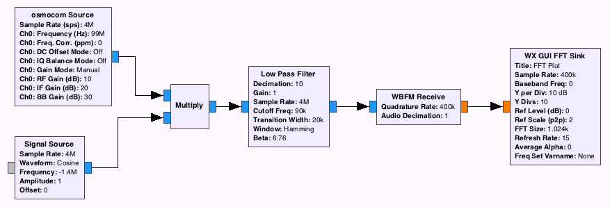
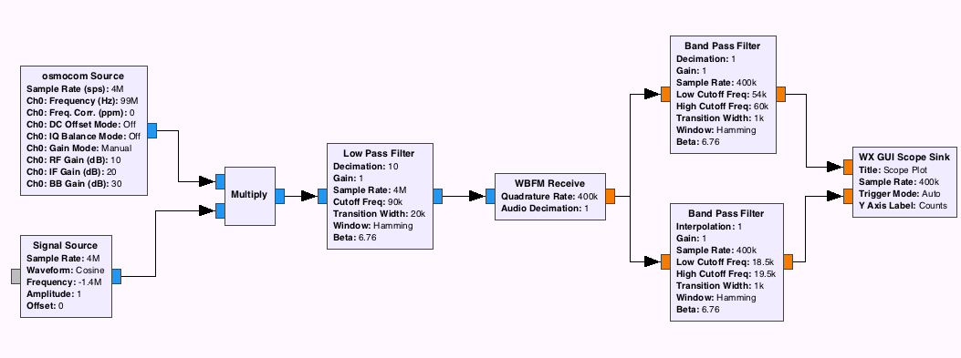
Since the original signal is frequency-modulated, we must first receive it in demodulated form. In order not to write another FM decoder, let's use the GNU Radio package. Run the GNU Radio Companion and build the circuit, as shown in the figure.
We are going to receive an FM station at a frequency of 100.4 MHz, for this we tune the receiver to 99 MHz, and programmatically “shift” the signal up through the frequency by 1.4 MHz, multiplying it by a signal with such a frequency. This is done because the SDR receiver has a peak at zero frequency relative to the center, and we cannot tune in immediately to the station.
Run the "scheme", and see the picture as
You can clearly see the pilot tone at 19KHz, the stereo signal at 38KHz and 2 peaks of the RDS signal around 57KHz.
Step 2. Isolation of the pilot tone and the RDS signal.
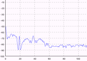
The next step is to select the pilot tone and the RDS signal. To do this, use a bandpass filter at the appropriate frequency.
We start the received scheme, and we see result, as in any "textbook" according to the description of RDS.
The pilot tone with a frequency of 19 KHz and the 57 KHz signal modulating a lower frequency signal with a frequency of 1187.5 Hz are clearly visible.
Step 3. Highlight the low-frequency signal.
To obtain the low-frequency signal requires 2 steps:
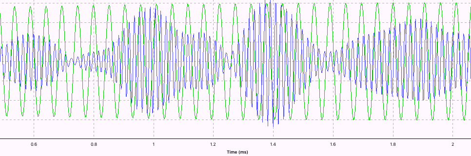
3.1) Reception of the 57KHz signal (3rd harmonic of the pilot tone).
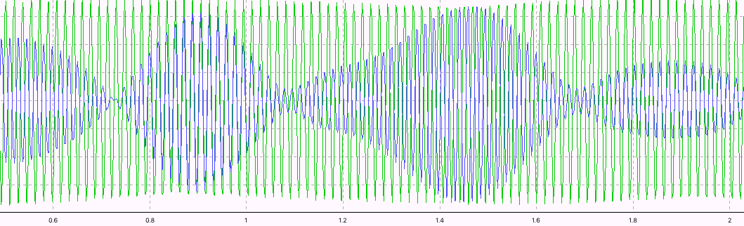
We have a 19KHz signal allocated by the filter, but how to get 57KHz from it? To do this, we recall school math, the sine cube formula:
As it is easy to see, the sine cube contains 2 components: sin (a) and sin (3 * a). Since we work with “analog” blocks, take in GNU Radio 2 blocks - a multiplier, and a high-pass filter. Removing sin (a) filter at 38KHz, we get the desired 57KHz.
The finished result can be seen on the oscillogram:
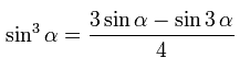
3.2) Reverse frequency transfer
When coding, the signal was transferred from the frequency 1187.5 Hz up, multiplying by 57 kHz. Now we perform the inverse operation, transfer the signal "down". To do this, once again multiply it by the 57KHz signal. According to the formula of the product of sines (the school program is a useful thing) we get 2 components - sums and differences of frequency. We need exactly the difference, the amount we discard using a low pass filter.
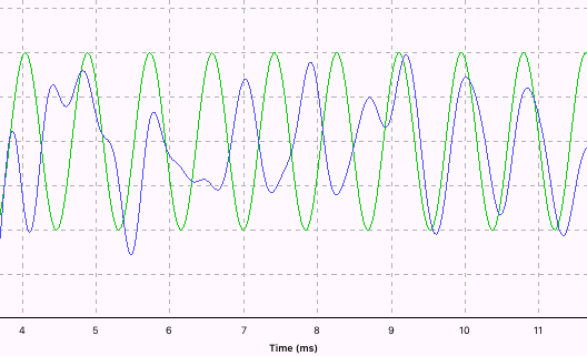
All this is done by adding blocks to GNU Radio, the final result is shown in the picture:
A green “model” signal with a frequency of 1187.5 Hz is shown in green to see that the conversion is correct.
Step 4. Demodulation of the low-frequency signal
The principle of this part is easiest to illustrate with a picture from a standard (“biphase symbol decoder” block).
Biphasic demodulation consists of 2 parts.
- "Reverse" signal inverter. This is needed to return from the biphasic coding, which was discussed above, to the original signal. In fact, you need to "flip" every second bit, so the process is synchronized with the clock signal.
- Summation of signals for the period. A positive amount corresponds to a bit "1", a negative "0".
By the way, the period of 1187.5 Hz is also not chosen by chance - it is the 19 KHz pilot tone frequency divided by 16. Everything is done to make the hardware implementation of the decoder in the receiver as easy as possible and, accordingly, cheaper.
After demodulation, the signal arrives at the differential decoder, which was discussed above. Then the signal arrives at the error correction module, but this is, as they say, a different story, corresponding to the second level of the OSI model.
If anyone is interested, the theoretical part can be continued, and consider the formation of packages. If anyone wants to experiment on their own, one of the options for a working decoder for RTL-SDR can be found on github . If you want to use a hardware tuner in your projects, you can buy a Si4703 FM RDS Tuner on eBay, its price is about $ 6.
Source: https://habr.com/ru/post/303104/
All Articles