vrf-table-label
Today we will talk about the team vrf-table-label. First, recall the methods for generating vrf tags. Labels can be generated in three ways - per-vrf, per-prefix and per-next-hop.
per-prefix - one label - one client prefix, that is, if we have 100 client vrfs and each client has 100 prefixes, then we get 100x100 = 10,000 tags, which is very wasteful by today's standards. This default vrf tag allocation method is used in Cisco routers.
per-next-hop - one label for all client prefixes that have the same next-hop. If the client router is connected to the PE router with one link, then all prefixes will have the same next-hop, which means the same label. This is the default vrf tag allocation mechanism in JunOS.
')
per-vrf - one label for the entire vrf. In terms of label distribution, this mode is very economical: if we have 100 client vrfs and each client has 100 prefixes, then we get 100x1 = 100 labels. With this distribution of vrf tags, the router should do besides the mpls lookup also the ip lookup.
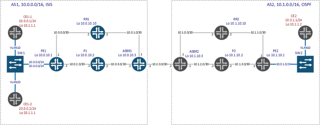
As it was written above, by default JunOS uses the per-next-hop label distribution. If you want to change this behavior, you will have to give the vrf-table-label command (for fans of confused configurations, the distribution of labels can be set using the policy) or use a tunnel PIC. Now we will analyze how everything works with this command and without it. We will use just such a scheme with Option C.
Without vrf-table label command (and creating vt-interface).
The configuration of vrf on PE1 is as follows:
Accordingly, the router begins to generate vpnv4 prefixes and transfer them to router reflectors. In our case, the router-reflector has the address 10.0.10.10:
PE1 sends four paths to the reflector: two connected networks and two / 32 (Lupbacks of CE routers), which it receives via ospf. Let's see what labels were generated for these prefixes:
For clarity, select only the values of the tags from the conclusions:
You can see that for prefixes from a range of 10.0.0.0/8, label 299888 is generated, and for prefixes from a range of 20.0.0.0/8, label 299904. But there is one not very pleasant nuance - in this case JunOS does not produce ip lookup. What does it threaten with? You will not be able to use filters, since the ip header is not analyzed.
Let's check it in practice.
According to the output below, PE1, having received a packet labeled 299904, simply sends it to the ge-0/0 / 3.20 interface:
and for packets labeled 299888 - to the interface ge-0/0 / 3.10:
As you can see, the router will remove the tag and send the packet to the interface depending on the incoming tag, without doing ip lookup, which we will now see.
Check the availability of vpnv4 routes on PE2:
Now let's look at the routing table on CE2:
Everything is great - there are routes. Now we can start tracing to 20.0.0.2 - address CE1-2:
Everything is predictable - standard tracing via Option C.

Now let's start tracing up to 20.0.0.1 - this is the address of the PE1 interface in the direction of the client (at the very beginning of the article the interface setting is shown)
Comparing the output with the previous one, we see that up to 20.0.0.1 one hop more. How so, because 20.0.0.1 - the gateway for the network 20.0.0.0/24? If you look closely, we see that the packet from the PE router (10.0.2.1 - core facing interface) was sent to the CE router (address 20.0.0.2) and returned to the PE router (20.0.0.1). As I said, JunOS didn’t do ip lookup and just forwarded the packet to the client interface, but the client’s router checked the destination address of the ip packet and sent it back to PE1 (see the figure below):

That is, in our case, the router received a packet with a tag from the network core, looked in the table mpls.0 what needs to be done with the packet, removed the tag and sent it to the interface in the direction of the client.

If we hang any filter on our PE router on the client interface or configure qos, in view of the above, the traffic will not be processed according to the installed filters.
Let's hang on the interface in the direction of the client filter:
And now we will launch a ping to the network 20.0.0.0/24 with CE2:
There is a filter, but it does not work. Let's change this situation by enabling the vrf-table label option:
Let's try to run the ping again to the network 20.0.0.0/24 with CE2:
Now the host is unreachable - the filter is working. Remove the filter and run the ping again to check:
All perfectly. Now we have seen clearly what pitfalls await us with the default mechanism for the distribution of vrf tags in JunOS. Since we have already given the vrf-table-label command above and have deactivated the filter, we’ll proceed to discuss the operation of the router with the vrf-table-label option enabled .
Let's see the routes that PE1 announces on the router:
bormoglotx @ PE1> show route advertising-protocol bgp 10.0.10.10
As you can see, now we have only one label for all routes from vrf CE1:
Run the trace again from CE2 to 20.0.0.1:
Now icmp packets do not loop through CE1-2.
The route itself on PE1 now looks a little different:
In the usual language, when receiving a packet with a label 16, you must remove the label and make an ip lookup in the table CE1.inet.0. Why is this function not implemented in Juniper when generating per-nex-hop tags? The point is Juniper hardware architecture - PFE cannot do both mpls and ip lookup at the same time. To implement a double lookup, we need the so-called Tunnel Services PIC, then a tunnel PIC (vt-fpc / pic / port.unit-number interface). Here is the PIC in the M120 chassis:

Note: You can read about creating a vt-interface and adding it to vrf
Now the packet processing algorithm will be changed: the router accepted the packet with a tag from the network core, looked in the mpls.0 table what needs to be done with the packet, removed the tag and sent it to the vt interface, then the packet from the vt interface again goes to the PFE, but without the tag and PFE can do ip lookup (and then send to the client).

But the need for a tunnel PIC imposes certain restrictions on the use of this function. Therefore, if you do not have such a PIC, then you can give the vrf-table-label command and JunOS automatically creates a virtual lsi (label switching interface) interface (supported by ACX, M, MX, T Series platforms) that performs exactly the same function as vt-interface:
This interface is not available for configuration. For each vrf, a separate lsi interface is created, which is associated with the label generated for this vrf. For example, create another vrf and see how many lsi interfaces are now:
You can see which lsi unit corresponds to a routing instance with the command: show interfaces lsi routing-instance-instance-name, for example, in our case:
The lsi interface is created for vpls routing-instance (no-tunnel-services command), the traffic is then processed as described above, except that vpls operates only mac addresses without knowing anything about client ip addresses, but this is completely other story.
Thanks for attention!
per-prefix - one label - one client prefix, that is, if we have 100 client vrfs and each client has 100 prefixes, then we get 100x100 = 10,000 tags, which is very wasteful by today's standards. This default vrf tag allocation method is used in Cisco routers.
per-next-hop - one label for all client prefixes that have the same next-hop. If the client router is connected to the PE router with one link, then all prefixes will have the same next-hop, which means the same label. This is the default vrf tag allocation mechanism in JunOS.
')
per-vrf - one label for the entire vrf. In terms of label distribution, this mode is very economical: if we have 100 client vrfs and each client has 100 prefixes, then we get 100x1 = 100 labels. With this distribution of vrf tags, the router should do besides the mpls lookup also the ip lookup.
As it was written above, by default JunOS uses the per-next-hop label distribution. If you want to change this behavior, you will have to give the vrf-table-label command (for fans of confused configurations, the distribution of labels can be set using the policy) or use a tunnel PIC. Now we will analyze how everything works with this command and without it. We will use just such a scheme with Option C.
Without vrf-table label command (and creating vt-interface).
The configuration of vrf on PE1 is as follows:
bormoglotx@PE1> show configuration routing-instances CE1 instance-type vrf; interface ge-0/0/3.10; interface ge-0/0/3.20; route-distinguisher 1:1; vrf-target { import target:2:100; export target:2:100; } protocols { ospf { export ospf-export; area 0.0.0.0 { interface ge-0/0/3.10; interface ge-0/0/3.20; } } } bormoglotx@PE1> show configuration interfaces ge-0/0/3 description "to SW1"; vlan-tagging; unit 10 { description "to CE1 site 1"; vlan-id 10; family inet { address 10.0.0.1/24; } } unit 20 { description "to CE1 site 2"; vlan-id 20; family inet { address 20.0.0.1/24; } } Accordingly, the router begins to generate vpnv4 prefixes and transfer them to router reflectors. In our case, the router-reflector has the address 10.0.10.10:
bormoglotx@PE1> show route advertising-protocol bgp 10.0.10.10 CE1.inet.0: 9 destinations, 9 routes (9 active, 0 holddown, 0 hidden) Prefix Nexthop MED Lclpref AS path * 10.0.0.0/24 Self 100 I * 10.1.1.1/32 Self 2 100 I * 20.0.0.0/24 Self 100 I * 20.1.1.1/32 Self 2 100 I PE1 sends four paths to the reflector: two connected networks and two / 32 (Lupbacks of CE routers), which it receives via ospf. Let's see what labels were generated for these prefixes:
bormoglotx@PE1> show route advertising-protocol bgp 10.0.10.10 detail CE1.inet.0: 9 destinations, 9 routes (9 active, 0 holddown, 0 hidden) * 10.0.0.0/24 (1 entry, 1 announced) BGP group RR type Internal Route Distinguisher: 1:1 VPN Label: 299888 Nexthop: Self Flags: Nexthop Change Localpref: 100 AS path: [1] I Communities: target:2:100 * 10.1.1.1/32 (1 entry, 1 announced) BGP group RR type Internal Route Distinguisher: 1:1 VPN Label: 299888 Nexthop: Self Flags: Nexthop Change MED: 2 Localpref: 100 AS path: [1] I Communities: target:2:100 rte-type:0.0.0.0:1:0 * 20.0.0.0/24 (1 entry, 1 announced) BGP group RR type Internal Route Distinguisher: 1:1 VPN Label: 299904 Nexthop: Self Flags: Nexthop Change Localpref: 100 AS path: [1] I Communities: target:2:100 * 20.1.1.1/32 (1 entry, 1 announced) BGP group RR type Internal Route Distinguisher: 1:1 VPN Label: 299904 Nexthop: Self Flags: Nexthop Change MED: 2 Localpref: 100 AS path: [1] I Communities: target:2:100 rte-type:0.0.0.0:1:0 For clarity, select only the values of the tags from the conclusions:
bormoglotx@PE1> show route advertising-protocol bgp 10.0.10.10 detail | match label VPN Label: 299888 VPN Label: 299888 VPN Label: 299904 VPN Label: 299904 You can see that for prefixes from a range of 10.0.0.0/8, label 299888 is generated, and for prefixes from a range of 20.0.0.0/8, label 299904. But there is one not very pleasant nuance - in this case JunOS does not produce ip lookup. What does it threaten with? You will not be able to use filters, since the ip header is not analyzed.
Let's check it in practice.
According to the output below, PE1, having received a packet labeled 299904, simply sends it to the ge-0/0 / 3.20 interface:
bormoglotx@PE1> show route table mpls.0 label 299904 mpls.0: 11 destinations, 11 routes (11 active, 0 holddown, 0 hidden) + = Active Route, - = Last Active, * = Both 299904 *[VPN/170] 00:46:19 > to 20.0.0.2 via ge-0/0/3.20, Pop and for packets labeled 299888 - to the interface ge-0/0 / 3.10:
bormoglotx@PE1> show route table mpls.0 label 299888 mpls.0: 11 destinations, 11 routes (11 active, 0 holddown, 0 hidden) + = Active Route, - = Last Active, * = Both 299888 *[VPN/170] 00:46:25 > to 10.0.0.2 via ge-0/0/3.10, Pop As you can see, the router will remove the tag and send the packet to the interface depending on the incoming tag, without doing ip lookup, which we will now see.
Check the availability of vpnv4 routes on PE2:
PE2#sh ip bgp vpnv4 rd 1:1 labels Network Next Hop In label/Out label Route Distinguisher: 1:1 10.0.0.0/24 10.0.10.1 nolabel/299888 10.1.1.1/32 10.0.10.1 nolabel/299888 20.0.0.0/24 10.0.10.1 nolabel/299904 20.1.1.1/32 10.0.10.1 nolabel/299904 Now let's look at the routing table on CE2:
CE2#sh ip rou | b Ga Gateway of last resort is not set 10.0.0.0/8 is variably subnetted, 5 subnets, 2 masks O E2 10.0.0.0/24 [110/10] via 10.0.1.1, 00:22:32, GigabitEthernet1/0.10 C 10.0.1.0/24 is directly connected, GigabitEthernet1/0.10 L 10.0.1.2/32 is directly connected, GigabitEthernet1/0.10 O E2 10.1.1.1/32 [110/10] via 10.0.1.1, 00:22:32, GigabitEthernet1/0.10 C 10.1.1.2/32 is directly connected, Loopback0 20.0.0.0/8 is variably subnetted, 2 subnets, 2 masks O E2 20.0.0.0/24 [110/10] via 10.0.1.1, 00:22:32, GigabitEthernet1/0.10 O E2 20.1.1.1/32 [110/10] via 10.0.1.1, 00:22:32, GigabitEthernet1/0.10 Everything is great - there are routes. Now we can start tracing to 20.0.0.2 - address CE1-2:
CE2#traceroute 20.0.0.2 Type escape sequence to abort. Tracing the route to 20.0.0.2 1 10.0.1.1 36 msec 32 msec 8 msec 2 10.1.3.2 [MPLS: Labels 20/18/299904 Exp 0] 56 msec 64 msec 60 msec 3 10.1.2.1 [MPLS: Labels 18/299904 Exp 0] 72 msec 108 msec 40 msec 4 10.2.0.1 [MPLS: Labels 299952/299904 Exp 0] 60 msec 88 msec 60 msec 5 10.0.3.2 [MPLS: Labels 299808/299904 Exp 0] 76 msec 68 msec 64 msec 6 10.0.2.1 [MPLS: Label 299904 Exp 0] 60 msec 52 msec 64 msec 7 20.0.0.2 60 msec 60 msec 56 msec Everything is predictable - standard tracing via Option C.
Now let's start tracing up to 20.0.0.1 - this is the address of the PE1 interface in the direction of the client (at the very beginning of the article the interface setting is shown)
CE2#traceroute 20.0.0.1 Type escape sequence to abort. Tracing the route to 20.0.0.1 1 10.0.1.1 40 msec 4 msec 16 msec 2 10.1.3.2 [MPLS: Labels 20/18/299904 Exp 0] 80 msec 64 msec 60 msec 3 10.1.2.1 [MPLS: Labels 18/299904 Exp 0] 56 msec 60 msec 72 msec 4 10.2.0.1 [MPLS: Labels 299952/299904 Exp 0] 48 msec 76 msec 112 msec 5 10.0.3.2 [MPLS: Labels 299808/299904 Exp 0] 68 msec 96 msec 64 msec 6 10.0.2.1 [MPLS: Label 299904 Exp 0] 80 msec 68 msec 4 msec 7 20.0.0.2 92 msec 72 msec 64 msec 8 20.0.0.1 96 msec 48 msec 88 msec Comparing the output with the previous one, we see that up to 20.0.0.1 one hop more. How so, because 20.0.0.1 - the gateway for the network 20.0.0.0/24? If you look closely, we see that the packet from the PE router (10.0.2.1 - core facing interface) was sent to the CE router (address 20.0.0.2) and returned to the PE router (20.0.0.1). As I said, JunOS didn’t do ip lookup and just forwarded the packet to the client interface, but the client’s router checked the destination address of the ip packet and sent it back to PE1 (see the figure below):
That is, in our case, the router received a packet with a tag from the network core, looked in the table mpls.0 what needs to be done with the packet, removed the tag and sent it to the interface in the direction of the client.
If we hang any filter on our PE router on the client interface or configure qos, in view of the above, the traffic will not be processed according to the installed filters.
Let's hang on the interface in the direction of the client filter:
bormoglotx@PE1# show firewall family inet filter To-CE1-2 term 1 { from { destination-address { 20.0.0.0/24; } } then { reject; } } term 2 { then accept; } [edit] bormoglotx@PE1# show interfaces ge-0/0/3.20 description "to CE1 site 2"; vlan-id 20; family inet { filter { output To-CE1-2; } address 20.0.0.1/24; } And now we will launch a ping to the network 20.0.0.0/24 with CE2:
CE2#ping 20.0.0.2 Type escape sequence to abort. Sending 5, 100-byte ICMP Echos to 20.0.0.2, timeout is 2 seconds: !!!!! Success rate is 100 percent (5/5), round-trip min/avg/max = 64/69/72 ms There is a filter, but it does not work. Let's change this situation by enabling the vrf-table label option:
[edit] bormoglotx@PE1# set routing-instances CE1 vrf-table-label Let's try to run the ping again to the network 20.0.0.0/24 with CE2:
CE2#ping 20.0.0.2 Type escape sequence to abort. Sending 5, 100-byte ICMP Echos to 20.0.0.2, timeout is 2 seconds: UUUUU Success rate is 0 percent (0/5) Now the host is unreachable - the filter is working. Remove the filter and run the ping again to check:
[edit] bormoglotx@PE1# deactivate interfaces ge-0/0/3.20 family inet filter [edit] bormoglotx@PE1# show | compare [edit interfaces ge-0/0/3 unit 20 family inet] ! inactive: filter { ... } CE2#ping 20.0.0.2 Type escape sequence to abort. Sending 5, 100-byte ICMP Echos to 20.0.0.2, timeout is 2 seconds: !!!!! Success rate is 100 percent (5/5), round-trip min/avg/max = 60/88/148 ms All perfectly. Now we have seen clearly what pitfalls await us with the default mechanism for the distribution of vrf tags in JunOS. Since we have already given the vrf-table-label command above and have deactivated the filter, we’ll proceed to discuss the operation of the router with the vrf-table-label option enabled .
Let's see the routes that PE1 announces on the router:
bormoglotx @ PE1> show route advertising-protocol bgp 10.0.10.10
CE1.inet.0: 9 destinations, 9 routes (9 active, 0 holddown, 0 hidden) Prefix Nexthop MED Lclpref AS path * 10.0.0.0/24 Self 100 I * 10.1.1.1/32 Self 2 100 I * 20.0.0.0/24 Self 100 I * 20.1.1.1/32 Self 2 100 I bormoglotx@PE1> show route advertising-protocol bgp 10.0.10.10 detail CE1.inet.0: 9 destinations, 9 routes (9 active, 0 holddown, 0 hidden) * 10.0.0.0/24 (1 entry, 1 announced) BGP group RR type Internal Route Distinguisher: 1:1 VPN Label: 16 Nexthop: Self Flags: Nexthop Change Localpref: 100 AS path: [1] I Communities: target:2:100 * 10.1.1.1/32 (1 entry, 1 announced) BGP group RR type Internal Route Distinguisher: 1:1 VPN Label: 16 Nexthop: Self Flags: Nexthop Change MED: 2 Localpref: 100 AS path: [1] I Communities: target:2:100 rte-type:0.0.0.0:1:0 * 20.0.0.0/24 (1 entry, 1 announced) BGP group RR type Internal Route Distinguisher: 1:1 VPN Label: 16 Nexthop: Self Flags: Nexthop Change Localpref: 100 AS path: [1] I Communities: target:2:100 * 20.1.1.1/32 (1 entry, 1 announced) BGP group RR type Internal Route Distinguisher: 1:1 VPN Label: 16 Nexthop: Self Flags: Nexthop Change MED: 2 Localpref: 100 AS path: [1] I Communities: target:2:100 rte-type:0.0.0.0:1:0 As you can see, now we have only one label for all routes from vrf CE1:
bormoglotx@PE1> show route advertising-protocol bgp 10.0.10.10 detail | match label VPN Label: 16 VPN Label: 16 VPN Label: 16 VPN Label: 16 Run the trace again from CE2 to 20.0.0.1:
CE2#traceroute 20.0.0.1 Type escape sequence to abort. Tracing the route to 20.0.0.1 1 10.0.1.1 32 msec 16 msec 20 msec 2 10.1.3.2 [MPLS: Labels 20/18/16 Exp 0] 76 msec 48 msec 68 msec 3 10.1.2.1 [MPLS: Labels 18/16 Exp 0] 68 msec 48 msec 56 msec 4 10.2.0.1 [MPLS: Labels 299952/16 Exp 0] 52 msec 48 msec 52 msec 5 10.0.3.2 [MPLS: Labels 299808/16 Exp 0] 52 msec 52 msec 52 msec 6 20.0.0.1 76 msec 52 msec 72 msec Now icmp packets do not loop through CE1-2.
The route itself on PE1 now looks a little different:
bormoglotx@PE1> show route table mpls.0 label 16 mpls.0: 10 destinations, 10 routes (10 active, 0 holddown, 0 hidden) + = Active Route, - = Last Active, * = Both 16 *[VPN/0] 00:04:23 to table CE1.inet.0, Pop In the usual language, when receiving a packet with a label 16, you must remove the label and make an ip lookup in the table CE1.inet.0. Why is this function not implemented in Juniper when generating per-nex-hop tags? The point is Juniper hardware architecture - PFE cannot do both mpls and ip lookup at the same time. To implement a double lookup, we need the so-called Tunnel Services PIC, then a tunnel PIC (vt-fpc / pic / port.unit-number interface). Here is the PIC in the M120 chassis:
Note: You can read about creating a vt-interface and adding it to vrf
Now the packet processing algorithm will be changed: the router accepted the packet with a tag from the network core, looked in the mpls.0 table what needs to be done with the packet, removed the tag and sent it to the vt interface, then the packet from the vt interface again goes to the PFE, but without the tag and PFE can do ip lookup (and then send to the client).
But the need for a tunnel PIC imposes certain restrictions on the use of this function. Therefore, if you do not have such a PIC, then you can give the vrf-table-label command and JunOS automatically creates a virtual lsi (label switching interface) interface (supported by ACX, M, MX, T Series platforms) that performs exactly the same function as vt-interface:
bormoglotx@PE1> show interfaces terse | match lsi lsi up up lsi.0 up up inet This interface is not available for configuration. For each vrf, a separate lsi interface is created, which is associated with the label generated for this vrf. For example, create another vrf and see how many lsi interfaces are now:
bormoglotx@PE1> show configuration routing-instances ? Possible completions: <[Enter]> Execute this command <instance_name> Routing instance name CE1 Routing instance name CE2 Routing instance name + apply-groups Groups from which to inherit configuration data + apply-groups-except Don't inherit configuration data from these groups | Pipe through a command bormoglotx@PE1> show interfaces terse | match lsi lsi up up lsi.0 up up inet lsi.1 up up inet You can see which lsi unit corresponds to a routing instance with the command: show interfaces lsi routing-instance-instance-name, for example, in our case:
bormoglotx@PE1> show interfaces lsi routing-instance CE1 | match logical Logical interface lsi.0 (Index 71) (SNMP ifIndex 524) bormoglotx@PE1> show interfaces lsi routing-instance CE2 | match logical Logical interface lsi.1 (Index 81) (SNMP ifIndex 525) The lsi interface is created for vpls routing-instance (no-tunnel-services command), the traffic is then processed as described above, except that vpls operates only mac addresses without knowing anything about client ip addresses, but this is completely other story.
Thanks for attention!
Source: https://habr.com/ru/post/303090/
All Articles