D3.js. Graph visualization
D3.js is a JavaScript library for managing documents based on data. D3 helps put data into practice using HTML, SVG, and CSS. D3 allows you to bind arbitrary data to the DOM, and then apply the results of manipulating them to the document.
For understanding the article, knowledge of the fundamentals of D3 is useful, and in it we will look at the implementation of the force-based graph algorithms visualization algorithms ( Force-graph graph drawing algorithms ), which in D3 (version 3) is called Force Layout . This is a class of graph visualization algorithms that compute the position of each node, simulating the force of attraction between each pair of connected nodes, as well as the repulsive force between the nodes.

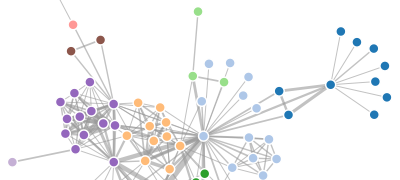
In the picture above, you can see how the notorious edition of the New Yourk Times visualized the connections between the candidates for the next Oscar. The final layout is static, but the positions of the nodes of the graph were calculated just with the help of Force Layout. An internal editor was built for the graph, allowing you to save the coordinates of the nodes for use in a static version.
NB! Just yesterday a new version (version 4) of D3.js was released, so the article I started can already be considered obsolete. Nevertheless, I hope that it will be useful for understanding the capabilities of the new version. You can read about the changes made in the new version in the graph visualization API here .
')
Little about layouts
The D3.js API contains several hundred functions, and for convenience they are divided into logical blocks, one of which is the Layouts block. It contains the functionality of visual display of data-related elements relative to each other. Layouts receive a series of input data, apply an algorithm or a heuristic to it, and output the result as a graphical representation of the data.
Layouts are not much different from the d3.svg path generators in that they help transform the data for their visual presentation. However, layouts tend to work with the data set as a whole, rather than separately. In addition, the results of Layout are not limited to one SVG. Some Layouts are dynamic in time: for example, Force Layout, where, after executing the .start () method of the d3.layout.force () instance, you can track the events of the tick update of the layout.
More than a dozen layouts are built into D3. Their instances are often functions (although not necessarily) that can be configured and then applied to the data set. In other cases, separate methods or event handlers are used to enter data and present the result. To use you need to look at the documentation of each particular Layout.
Force layout
The flexible force-directed graph is visualized using Verlet’s numerical integration method to impose restrictions on the movement of graph elements relative to each other. Read more about physical modeling here . This implementation uses the quadtree module (quad tree) to accelerate the interaction of the nodes of the graph between themselves, using the Barnes-Hut approximation . In addition to the repulsive force of the charge node, the pseudo-gravitational force gravity holds the nodes in the visible region and avoids pushing unbound subgraphs out of scope, while the graph links have a fixed length of linkDistance and act as geometric constraints. Additional user effects and restrictions can be applied in the 'tick' event, by updating the x and y attributes of the nodes.
For a comprehensive overview of the possibilities with examples, see the video report of one of the key D3 developers Mike Bostock and a presentation from this report.
Some amusing examples are: divergent forces , graphical constructor , force-driven tree , power-driven symbols , power sticky law .
Like the other classes in D3, Layouts follow method chaining when the setter methods return their Layout, allowing you to build many setters into a single chain of calls. Unlike some other implementations of Layouts, Force Layout retains a link to nodes and graph links within itself; thus, each Force Layout instance can be used with only one dataset.
d3.layout.force ()
Creates a new force-directed layout with the following default settings: size 1 × 1, link strength 1, friction 0.9, distance 20, charge strength -30, gravity strength 0.1, theta parameter 0.8 (these parameters will be described below). By default, nodes and graph links are empty arrays, and when the Layout starts, the internal cooling parameter alpha is set to 0.1. The general template for building force-directed layouts is setting all configuration properties, and then calling the .start () method:
var force = d3.layout.force() .nodes(nodes) .links(links) .size([w, h]) .linkStrength(0.1) .friction(0.9) .linkDistance(20) .charge(-30) .gravity(0.1) .theta(0.8) .alpha(0.1) .start(); Please note that, unlike other D3 Layouts, the force-directed layout is not associated with a specific visual representation. Usually nodes are displayed as SVG elements of a circle, and links are displayed as SVG elements of a line. But you can also display nodes as symbols or images .
force.size ([width, height])
If the size parameter is passed, sets the available layout size (width and height). Otherwise, it returns the current size, which by default is [1, 1]. In the force-directed layout, size affects two things: the gravity center and the initial random position of the nodes being added (their x and y coordinates). The center of gravity is calculated simply [x / 2, y / 2]. When adding nodes to the Force Layout, if they do not have the x and y attributes already set, then these attributes are initialized using a uniform random distribution in the range [0, x] and [0, y], respectively.
force.linkDistance ([distance])
If the distance parameter is passed, it sets the distance between the connected nodes (the length of the links) specified in it. Otherwise, it returns the current link length, which defaults to 20. If distance is a constant, then all links will have the same length. Otherwise, if distance is a function, then this function is calculated for each connection (in order). The function takes two arguments — link and its index; The context for
this function is set to the current Force Layout. The return value of the function is used to set the length of each link. The function is calculated at startup (method . Start () ) of the layout.Connections are implemented not as “elastic forces”, which is common in other force-directed layouts, but as weak geometric constraints. For each 'tick' event of the layout, the distance between each pair of connected nodes is calculated and compared with the target distance; then the bonds move closer or farther from each other until they meet at the right distance. This approach, coupled with Verlet’s numerical integration method, is much more stable than the approaches using elastic forces, and also allows for a flexible implementation of other constraints in the 'tick' event handler, such as a hierarchical representation.
force.linkStrength ([strength])
If the strength parameter is passed, sets the specified bond stiffness in the range [0,1]. Otherwise, it returns the current stiffness, which defaults to 1. If the strength is a constant, then all the connections will have the same stiffness. Otherwise, if strength is a function, then this function is calculated for each connection (in order). The function takes two arguments — link and its index; The context for
this function is set to the current Force Layout. The return value of the function is used to set the stiffness of each bond. The function is calculated at startup (method . Start () ) of the layout.force.friction ([friction])
If the friction parameter is passed, sets the specified friction coefficient. Otherwise, it returns the current coefficient, which is 0.9 by default. The name of this parameter may be misleading; it does not comply with the standard friction coefficient (from physics). Rather, it is more similar to the damping rate: for each 'tick' event of the modeling process, the speed of the nodes is calculated based on the friction parameter. Thus, the value 1 corresponds to a friction-free medium, and the value 0 freezes all nodes in place. Values outside the [0,1] range are not recommended and may have destabilizing effects.
force.charge ([charge])
If the charge parameter is transferred, sets the specified charge power of the node. Otherwise, it returns the current charge strength, which by default is -30. If charge is a constant, then all nodes will have the same charge force. Otherwise, if charge is a function, then this function is calculated for each node (in order). The function takes two arguments - the node and its index; The context for
this function is set to the current Force Layout. The return value of the function is used to set the charge strength of each node. The function is calculated at startup (method . Start () ) of the layout.The negative value of the charge force leads to the repulsion of the nodes, and a positive value leads to the attraction of the nodes. Negative values should be used to represent the graph; To simulate the problem of N bodies , positive values can be used. All nodes are assumed to be infinitely small points with equal charge and mass. The charge forces are effectively implemented using the Barnes-Hut algorithm by calculating a quad tree for each 'tick' event. Setting the charge strength to 0 disables the quad tree calculation, which can significantly improve performance if you do not need this functionality.
force.chargeDistance ([distance])
If the distance parameter is transmitted, sets the maximum distance at which the node's charge forces act. Otherwise, it returns the current maximum distance, which defaults to infinity. Determining the end distance improves the performance of the Force Layout and gives a more localized layout output; This is especially useful in conjunction with gravity user gravity .
force.theta ([theta])
If the theta parameter is passed, sets the criterion for the Barnes-Hut approximation. Otherwise, returns the current value, which defaults to 0.8. Unlike links, which affect only two connected nodes, the charge power is universal: each node affects all other nodes, even if they are located on uncoupled subgraphs.
To avoid delays associated with quadratic time complexity, Force Layout uses the Barnes-Hut algorithm , which has O (n log n) time complexity for one 'tick' . For each 'tick' event, a quad tree is created to save the current position of the node; then for each node the sum of the forces of charges of all other nodes is calculated. For groups of nodes that are far away, the charge force is approximated by treating the remote group of nodes as one large node. Theta determines the accuracy of the calculation: if the ratio of the quadrant area in the quadrant tree to the distance between the node and the center of mass of the quadrant is less than theta , all the nodes in this quadrant are treated as one large node and not calculated separately.
force.gravity ([gravity])
If the gravity parameter is passed, sets the gravitational pull force. Otherwise, it returns the current gravitational force, which defaults to 0.1. The name of this parameter may be misleading; it does not correspond to physical gravity (which can be simulated by assigning a positive value to the charge parameter). Instead, the gravity parameter is implemented as a small geometric constraint, like a virtual spring, connecting each node to the center of the layout. This approach has remarkable properties: near the center of the layout, the force of gravitational attraction is practically zero, which prevents any local distortion of the layout; since the nodes are extended further from the center, the force of gravitational attraction increases in linear proportion to the distance. Thus, the force of gravitational attraction will always overcome the repulsive forces of charge on a certain threshold, preventing the release of disconnected nodes beyond the boundaries of the layout.
Gravity can be turned off by setting the gravitational attraction force to zero. When gravity is turned off, it is recommended to implement some other geometric constraint to prevent knots from leaving the boundaries of the layout.
force.nodes ([nodes])
If the nodes parameter is passed, installs the graph nodes specified in the array. Otherwise, it returns the current array of nodes, which is empty by default. Each node has the following attributes:
- index - index (counting index from 0) of the node in the nodes array.
- x - the x coordinate of the current position of the node.
- y - the y coordinate of the current node position.
- px - the x coordinate of the previous position of the node.
- py - the y coordinate of the previous node position.
- fixed - a boolean value that indicates whether the position of the node is fixed.
- weight is the number of edges associated with the node.
You do not need to set these attributes before passing the Force Layout node; if they are not set, the corresponding default values will be initialized by Force Layout when calling the .start () method. However, keep in mind that if you store any other data in your nodes, your data attributes should not conflict with the above properties used by Force Layout.
force.links ([links])
If the links parameter is passed, sets the graph links specified in the array. Otherwise, it returns the current array of links, which is empty by default. Each link has the following attributes:
- source - the start node (element of the nodes array)
- target - final node (element of the nodes array)
Note: the values of the source and target attributes can be initially specified as indices in the array of nodes; they will be replaced by references after calling the .start () method. Link objects may have additional user-defined fields; This data can be used to calculate the stiffness of the linkStrength of the connection and the distance of the linkDistance between the communication nodes using the access function.
force.start ()
Starting the modeling process; This method should be called when creating a Force Layout, after installing nodes and links. In addition, it needs to be called again when nodes or links change. Force Layout uses the “cooling” parameter alpha , which controls the temperature. Force Layout: since physical modeling is reduced to a static layout, the temperature decreases, resulting in the nodes slowing down. Ultimately, alpha drops below a certain threshold, and the simulation stops completely, freeing resources. Force Layout can be re-warmed using the .resume () method or by restarting; this also happens automatically when using the drag mode.
When launched, Force Layout initializes various attributes of its associated nodes. The index of each node is calculated by iterating over the array, starting from 0. The initial coordinates of the node x and y, if not specified, are calculated based on the neighboring nodes: if the associated node already has an initial value of x and y, the corresponding coordinates are applied to the new node. This increases the stability of the graph's layout when adding new nodes, in contrast to the use of default values, which initialize the coordinates randomly within the dimension of the layout. The coordinates px and py of the previous position of the node (if not specified) take the value of the initial coordinates, which gives the new nodes an initial speed of zero. Finally, the default value of fixed is false.
Force Layout also initializes the source and target attributes of links links: these attributes can be set not only by direct links to nodes, but also by numerical indexes of nodes (this is convenient when reading data from a JSON file or other static description). The source and target attributes of links are replaced with the corresponding entries in nodes only if these attributes are numbers; thus, these attributes are not affected on existing connections when the Force Layout is restarted. The linkDistance and linkStrength links parameters are also calculated at startup.
force.alpha ([value])
Gets or sets the “cooling” alpha parameter of the Force Layout modeling process. If passed, sets the alpha parameter and returns Force Layout. If the value passed is greater than zero, this method also restarts Force Layout, if it is not already running, causing a 'start' event and including a 'tick' timer. If the value passed is not positive and Force Layout is started, this method stops the Force Layout on the next 'tick' event and raises the 'end' event. If no value is specified, this method returns the current value of the “cooling” parameter.
force.resume ()
Equivalent to calling:
force.alpha(.1); Sets the “cooling” parameter alpha to 0.1 and then restarts the timer . As a rule, you do not need to call this method directly; it is called automatically by the .start () method. It is also called automatically by the .drag () method when dragging.
force.stop ()
Equivalent to calling:
force.alpha(0); Terminates the simulation process by setting the cooling parameter alpha to 0. This method can be used to explicitly stop the simulation process. Unless you explicitly stop the Force Layout, this will happen automatically after the alpha “cooling” parameter drops below a certain threshold.
force.tick ([value])
Performs one step of Force Layout modeling. This method can be used together with the .start () and .stop () methods to calculate the static layout. For example:
force.start(); for (var i = 0; i < n; ++i) force.tick(); force.stop(); The number of iterations depends on the size of the graph and its complexity. Choosing initial positions is also important. For example, here the nodes are located diagonally:
var n = nodes.length; nodes.forEach(function(d, i) { dx = dy = width / n * i; }); If you do not initialize the positions of the nodes manually, Force Layout initializes them randomly, leading to a somewhat unpredictable approach.
force.on ([type, listener])
Registers a specific listener to handle event types of a specific type from Force Layout. Currently only 'start' , 'tick' , and 'end' events are supported.
Event objects that are passed to a handler function are user objects created using d3.dispatch () . Each event object has two properties: type (string, 'start', 'tick', or 'end'), and alpha, which is the current value of the “cooling” alpha parameter. The event.alpha property can be used to monitor the progress of Force Layout modeling or to make your own adjustments to this process.
The 'start' event is sent both at the initial start of the simulation process, and every time the simulation is restarted.
The 'tick' event is dispatched at each simulation step. Track 'tick' events to update the displayed positions of nodes and links. For example, if you initially display nodes and links as follows:
var link = vis.selectAll("line") .data(links) .enter().append("line"); var node = vis.selectAll("circle") .data(nodes) .enter().append("circle") .attr("r", 5); You can set their positions for each step of the modeling process:
force.on("tick", function() { link.attr("x1", function(d) { return d.source.x; }) .attr("y1", function(d) { return d.source.y; }) .attr("x2", function(d) { return d.target.x; }) .attr("y2", function(d) { return d.target.y; }); node.attr("cx", function(d) { return dx; }) .attr("cy", function(d) { return dy; }); }); In this case, we saved a set of nodes (node) and links (link) during the initialization stage, so that we do not need to re-select nodes at each modeling step. You can optionally display nodes and links in a different way; for example, you can use symbols instead of circles.
The 'end' event is dispatched when the internal “cooling” parameter alpha drops below the threshold value (0.005) and is reset.
force.drag ()
Associates behavior with nodes for interactive dragging, both mouse and touch. Use it in conjunction with the call method for nodes; for example, call node.call (force.drag) to initialize. In drag mode, when you hover the mouse over a node, its fixed attribute is set to true, thereby stopping its movement. Fixing a node when the mouseover (mouseover), in contrast to the fixation when clicking on the node (mousedown), simplifies the task of trapping the desired node. When the 'mousedown' event occurs, and for each subsequent 'mousemove' event up to the 'mouseup' event, the center of the node is set to the current mouse position. In addition, each mousemove event triggers the Force Layout .resume () method, “warming up” the modeling process. If you want the moved nodes to commit after dragging, set the fixed attribute to true on the 'dragstart' event, as done in this example .
Implementation note : the 'mousemove' and 'mouseup' event handlers are registered for the current window, so that when the user starts dragging a node, the dragging process will not stop even if the mouse cursor goes beyond the limits of the layout. Each event handler uses the force namespace to avoid conflicts with other event handlers that a user can bind to nodes or to a window. If a node is moved by dragging and dropping, the subsequent 'click' event, which will be triggered when the mouse button is released ('mouseup'), will be canceled. If you register a 'click' event handler, you can ignore the 'click' events that occur when dragging, as follows:
selection.on("click", function(d) { if (d3.event.defaultPrevented) return; // ignore drag otherwiseDoAwesomeThing(); }); Finally, check out these two examples: collapsible force layout and divergent forces .
Source: https://habr.com/ru/post/302968/
All Articles