BGP Inter-AS
Today we will talk about "inter-operator" interaction - BGP Inter-AS. These options are used when necessary to proxy L3vpn between PE routers located on different autonomous systems. It should be clarified that these options are used mostly within companies when they take over / merge networks, for interaction between branches of one company if they have their own autonomous systems and their mpls domains.
The article will cover the following topics:
- BGP Inter-AS Option A
- BGP Inter-AS Option B
- BGP Inter-AS Option C
- Features of setting these options on JunOS
This article will draw a lot of insights from the Cisco and Juniper CLIs. If you do not know the basics of mpls, the difference between bgp labeled-unicast and vpnv4 unicast, then you do not need to read this article. If these concepts are familiar to you, then please under the cat.
Note: In the diagrams below, the left side consists of routers running JunOS (except CE), on the right side of Cisco IOS15.
Well, let's start with the most banal - Option A.
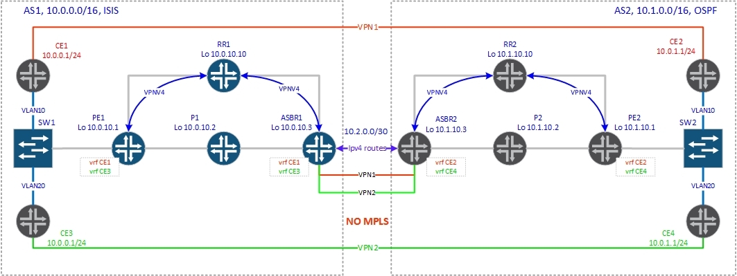
The meaning of this option is that on ASBRs, VRFs are created for each VPN and separate subinterfaces from the neighboring AS are raised. In this way, ASBRs interoperate as CE-PE routers, exchanging clear IP routes. In this option, there is no MPLS between ASBRs - only pure IP traffic:
Let us examine in more detail how the control plane works:
')
1. PE1 generates a vpnv4 route and sends it via MP-BGP to router reflector (RR1).
2. Routereflector has a vpnv4 session with ASBR1, within which it gives it a route received from PE1 vpnv4.
3. Since VRF was also created on ASBR1 (in our topology on ASBR1 CE1 and CE3, and on ASBR2, CE2 and CE4), it takes the route and installs it into the routing table of the corresponding vrf.
4. ASBR1 transmits an already clear IP version to ASBR2 (the routing protocol can be any, from RIP to BGP). Here, the interaction is of the type from CE to PE, where ASBR1 will act as the CE of the router, giving the IP prefix, and ASBR2 - the PE of the router, receiving the prefix and generating the vpnv4 prefix for its AS. (routes are transmitted from both sides, therefore both ASBRs play the role of both CE and PE of the router).
5. ASBR2, having received an IP prefix, generates a vpnv4 prefix and sends it to its router reflector (RR2).
6. PE2 receives from the router a given vpnv4 session prefix and installs it into the routing table of the corresponding vrf, first checking the next-hop reachability and rt in the route configured on the vrf-import router.
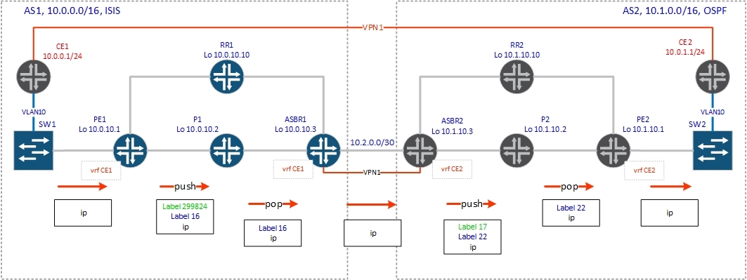
Now for the data plane:
1. PE1 receives a packet from CE1, sticks a tag (vrf tag) received from ASBR1, a transport tag to ASBR1 (received via ldp) and sends it to the appropriate interface.
2. P1 receiving a packet from PE1 with a stack of 2-x tags removes the top transport tag (php) and sends the packet to ASBR1.
3. ASBR1 receives a packet with a single label (vrf tag), and acts as a normal PE router, terminating the client CE router — removes the label and sends the packet to the appropriate interface, but since the CE role of the router in this scenario is performed by ASBR2, the pure IP packet sent to the joint c ASBR2.
4. ASBR2 receives this packet and works as a normal PE router — adds a vrf tag (received from PE2), a transport tag to PE2 (obtained via ldp) and sends it to the appropriate interface.
5. P2 removes the transport tag (php).
6. PE2 receives a packet with a single tag (the vrf tag that it itself generated), removes it, does an ip lookup and sends the packet according to the routing table of the corresponding vrf.
Now let's look in practice, what operations with labels will be made.
Below are the BGP configurations on ASBRs:
Everything, as you can see, like a regular PE router, is nothing criminal.
Note: There are several nuances with regards to routing protocols. If you are using BGP, then you may have to use the loops 2 command, if you link two client sites with the same autonomous system numbers, and if you have, for example, OSPF everywhere, then you should not forget about the DN bit. Each individual case must be considered separately.
So, we created vrf CE1 on PE1 and ASBR1, and vrf CE2 on PE2 and ASBR2, as shown in the diagram. Export and import of vpnv4 routes is possible only between vrf-mi data within the autonomous system. Only ASBRs (and ipv4 unicast) exchange routes between autonomous systems. Check the connectivity between client routers CE1 and CE2:
Everything is fine, there is connectivity. Now we will consider what operations with tags will occur in the course of package promotion.
So, see the route on PE1:
PE1 sticks two tags:
16 - vrf tag received via RR1 from ASBR1
299824 - transport label obtained by the ldp protocol
and sends the packet to the interface ge-0/0 / 0.0 towards P1.
P1 according to the table mpls.0 (since it is a transit router) removes the top label (works out the php mechanism) and sends this packet to ASBR1:
ASBR1 removes the vrf label and makes an ip lookup in the CE1.inet.0 table (do not forget to give the vrf-table-label command on JunOS):
The packet from ASBR1 is transmitted via ge-0/0/3 interface to ASBR2 without mpls header — only pure ip traffic (usually tagged, in our case only one vrf, so I did not make subinterfaces when you have several vrfs, you have to make a separate subinterface for each vpn and specify it in the vrf settings).
ASBR2, having received an IP packet, looks for a route in the routing table of vrf CE2:
According to the route, ASBR2 hangs the vrf (22) tag received by bgp vpnv4 from PE2 and sends it to lsp to PE2 (10.1.10.1). Next-hop in the route is P2 or RR2 (in our case the reflector works as a P-router). We assume that the traffic will go through P2 and we will look at operations with labels on it. P2 receives a packet with two labels 22 and 17, looks in mpls forwarding-table:
According to mpls forwarding-table, P2 removes the top tag (php again) and sends the packet to PE2.
PE2 sees that this label points to vrf CE2, produces an ip lookup in the vrf CE2 table and sends a clear ip packet to the client:
It is clear that this solution is quite difficult to scale. If you connect a new client, then you will need to create vrf not only on the PE router, on which this client will be terminated, but also on the ASBR (and they will have to do the same on the other side). Naturally, this solution does not satisfy today's requests of telecom operators, so we will move on to considering more interesting solutions - options B and C.
Option B.
Between the ASBR, a vpnv4 session is raised, within which vpnv4 routes are exchanged (of course, it is necessary to set up filtering on the ASBR of the given and received prefixes, so as not to give or not get something extra). But we know that the router drops the vpnv4 routes (except Juniper routers) if it does not have a VRF to which (s) these routes are intended (if the target-target specified in the NLRI is not in any of the import vrfs). To change this default behavior on the ASBR, you must enable all vpnv4 routes (keep all - Juniper, no bgp default route-target filter - IOS, retain route-target all - IOS XR, undo policy vpn-target - Huawei).
Note: on Juniper routers, there is no need to keep all command, because when configuring an eBGP vpnv4 session, the router automatically considers itself an ASBR for option B, therefore it accepts and installs all routes received from peers of vpnv4 into the bgp.l3vpn.0 table and sends these routes to their feasts.
Let's start with the control plane:

1. PE2 generates a vpnv4 route and sends it to the router reflector RR2.
2. Route reflector RR2 forwards this route to all its clients.
3. ASBR2, being a client of the reflector, receives the generated PE2 vpnv4 route. Since the no bgp default route-target filter option is enabled on it, ASBR2 installs the received route into the routing table.
4. ASBR2 changes the next-hop route received from the router reflector to itself, generates a new label (and the value of the label may not change) and sends this route to the ASBR1 via ebgp vpnv4 session.
5. ASBR1 takes the vpnv4 route from ASBR2 and installs it in the routing table bgp.l3vpn.0.
6. ASBR1 changes the next-hop route received from ASBR2 to itself, generates a new mpls tag and sends this route to RR1.
7. RR1, having received this route, checks the availability of next-hop, as-path (the standard mechanism for choosing the best route bgp) and installs this route into its routing table.
8. RR1 sends the route received from ASBR1 to PE1.
9. PE1, having received the vpnv4 route from the router, checks the availability of the next-hop, checks whether extremity (rt) in the received route matches the configured vrf-import router and installs it into the routing table of the corresponding vrf.
Transport tags to ASBR within AS are distributed in a standard way - LDP or RSVP-TE.
Now let's look at the above with an example:

Consider how the label will be signaled for the client prefix 10.0.1.0/24, which is terminated on PE2 vrf CE2:
PE2 generates a vpnv4 route and sends it via iBGP to the RR2 router:
According to the above output, label 17 is generated for this prefix: mpls labels in / out 17 / nolabel (CE2)
Next, PE2 sends vpnv4 routes to the router. There are two routes, since one is the network between PE2 and CE2, and the second is a loopback client router CE2.
Route reflector RR2 passes the route received from PE2 vpnv4 to its clients, including ASBR2:
ASBR2 accepts this route and installs it into the routing table:
Pay attention to the line "mpls labels in / out 26/17". ASBR2 generates a new label on in - 26 and sends all its existing vpnv4 routes (or not all if filtering is set to out) to the next AS on ASBR1:
ASBR1 accepts these routes and installs to the routing table:
Besides the fact that ASBR2 generated a new label, he also changed next-hop to himself (Nexthop: 10.2.0.2).
ASBR1 generates a new label (VPN Label: 299888) to the prefix 10.0.1.0/24, changes the next-hop to itself (Nexthop: Self) and gives the route to the router-reflector RR1
Route reflector RR1 gives the route to its customers, including PE1:
We see the route in two tables: in the vrf CE1.inet.0 table and in the bgp vpnv4 table of the bgp.l3vpn.0 routes.
When receiving vpnv4 routes, JunOS checks them for suitability (AS-PATH, next-hop availability), whether there is a routing instance for import specified in the vpnv4 route in the configuration, and if the route passes these checks and is selected by the best according to the bgp staff selection algorithm best path , it is installed on the bgp.l3vpn.0 table. And already from this ip table, the prefix is transferred to the vrf table (CE1.inet.0 in our case).
Data-plane:

With the alarm tags, we figured out. Now consider the data plane, that is, how the packet will be sent from CE1 (from 10.0.0.2) to CE2 (10.0.1.2) via the “mpls cloud”.
First, let's start ping between CE routers and make sure that there is connectivity between the hosts:
Now we will do the trace:
It is seen that the maximum number of tags - 2.
Note: there may be more if you use traffic-engineereng. In our case, the label distributes only ldp.
Now let's deal with label operations when a packet is moving over the network.
On PE1, a pure IP packet arrives from the CE1 client router (in our case with the vlan tag 10, but this does not matter, since this is l3vpn and the tag is removed). The route to PE1 indicates that the packet must be sent to the mpls tunnel. PE1 hangs two tags: the vrf tag is 299888 (which we received from ASBR1) and the transport tag to ASBR1 is 299792 (obtained via the ldp protocol):
PE1 sends this packet to the interface ge-0/0/1 towards RR1 (in our case, the router also performs the function of the P-router).
RR1 receives a packet with a stack of tags and analyzes the top tag 299792:
According to the table mpls.0, RR1 removes the label (php) and sends the packet to the interface ge-0/0 / 0.0 towards ASBR2.
ASBR2 receives a stake with only one mark 299888. We look at what it should do:
ASBR1 swaps the tag 299888 to tag 26 and sends the packet through the junction with AS2 to ASBR2.
Further, ASBR2 also produces a swap of the mark 26 on the mark 17 (he received it from PE2)
So, as the next-hop route is 10.1.10.1, then ASBR2 must also add a transport label (19) to PE2:
The packet is sent to RR2 or P2, since the paths are equivalent ... Let's see what it will do with this P2 packet:
P2 removes the tag and sends a packet with one tag to PE2.
PE2 receives a packet with a single tag 17, which is the vrf tag. In this case, the distribution of labels on the prefix is used (one label is one client prefix), which in real life is naturally too wasteful, therefore the distribution mode of the labels must be switched - per-vrf (one label per vrf). Unlike Cisco, JunOS default label distribution mechanism is per-next-hop. If the client has an Ethernet link, which is natural in the overwhelming majority of cases, then it is necessary to enable per-vrf tag generation with the vrf-table-label command. The principle of packet processing in this case is changing, and is worthy of a separate article.
According to the above information, PE2 removes the label 17, does an ip lookup in the vrf CE1 table and sends the packet to the client.
ASBR configurations:
I would like to add that there are two types of Option B. We have considered the first method - the most common - the ASBR performs the substitution of the next-hop when passing a route inside an autonomous system (when passing a route to a reflector). The second way is that the ASBR, as expected for the ibgp session, when announcing the route to the reflector did not replace the next-hop to its address. But then the network between the ASBRs should be announced in the IGP (you can link between the ASBRs to make a passive interface or prescribe statics on the ASBRs and redistribute it into the IGPs). This is necessary so that the PE routers can set the BGP route to their tables (next-hop availability check) and ldp generates a label to this prefix.
With Option B I think sorted out. We turn to Option C.
Option C
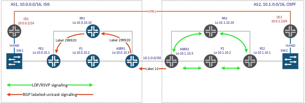
The vpnv4 routes are exchanged between different AS router-reflectors directly through the ebgp-multihop session, and the ASBR-ry has the task of distributing routes with mpls tags to the loopbacks of the router and PE routers of the neighboring autonomous system.
Consider how the control plane works:

Distribution of transport tags:
1. ASBR2 protocol ldp receives from its neighbors label to PE2.
2. ASBR2, according to the configured policy, generates routes with labels to the Lubeks of its autonomous system and sends these routes to ASBR1 via bgp labeled-unicast, indicating itself in the next-hop route.
3. ASBR1 takes the labeled-unicast route from ASBR2 and installs them in mpls forwarding table.
4. ASBR1 generates labels for routes received from ASBR2, points itself to next-hop and gives routes to RR1.
5. RR1, having received these routes, checks the route for validity, installs it in its routing table and sends it to all the rest of its customers.
6. PE1, after receiving the labeled-unicast route from the router, performs its validation and installs the route into the routing table.
Vrf label distribution:
1. PE2 generates a vpnv4 route and sends it to the router reflector RR2.
2. Route reflector RR2 forwards this route to all its clients and RR1 via eBGP multihop session without changing the next-hop and label values.
3. RR1 transmits the route received from RR2 to all its customers, including PE1.
4. PE1 checks the route for suitability and sets the corresponding vrf in the routing table.
The vrf and transport labels are distributed.
Now let's see how this all works in practice. First, we need to distribute the loopback routes between autonomous systems, since our vpnv4 session between the router reflexors does not rise due to the lack of a route to the remote router reflector. We will distribute routes with labels at once between autonomous systems, so there will only be a labeled-unicast session between ASBRs (we don’t need ipv4 prefixes without tags). But if you need both address families, you will need to specify that the labeled-unicast routes need to be installed in inet.3 (otherwise, on JunOS you don’t raise the two ibv4 and ipv4 labeled-unicast address families in one session).
Bgp configuration on ASBR1 (session with ASBR2):
Let's see how the signaling of the tag to the loopback PE2 will work.
So, inside the autonomous system, we run ldp and the tags to the loopbacks automatically fly throughout the AS. Naturally, ASBR2 has tags up to the loopbacks of all AS2 routers. Now ASBR2 should generate routes with labels to the loopbacks of its AS and transfer them to ASBR1. We'll see:
As can be seen from the output, ASBR2 generated a label before the prefix 10.1.10.1 to in, equal to 22.
Let's see this route on ASBR1:
We are interested in the output label: 22 and next-hop: 10.2.0.2 (address of the ASBR2 interface). Now ASBR1 knows how to get to PE2.
Further, this route through the labeled -unicast session is transmitted to the reflector and distributed from it inside the autonomous system between the PE routers. But there is one thing: if ASBR1 passes the route in the same form as it received from ASBR2, it will not work, because there is no route to the network 10.2.0.0/30 (the network between ASBRs) inside the autonomous system. Therefore, ASBR1 changes the next-hop to itself and generates a new label:
Now let's see this route on PE1:
That's right, label 299920 is used to get to PE2.In the output, we also see another label 299776, that is, we have a stack of labels. On the appointment of the second (299776) will be written below).
Great, now we have end-to-end lsp between PE1 and PE2. As a matter of fact, there is also lsp between the reflectors now, as the routes to RR1 and RR2 are also given with labels. After we have distributed the lupbek routes between autonomous systems, the neighborhood rises between the router reflectors:
Vpnv4 routes are distributed between reflectors: NLRI for this session: inet-vpn-unicast.
We accept 2 prefixes from the neighbor: Accepted prefixes: 2
And give the same amount: Advertised prefixes: 2
I think this is understandable.
Reflector settings:
Note: In the RR2 configuration (Cisco IOS15), some of the lines not related to 10.0.10.10 are removed to reduce the size of the output.
Now we can see how the distribution of vrf tags works:

PE2 generates a route to the network 10.0.1.0/24, which is terminated in vrf CE1
As you can see, label 22 was generated.
Next, the route is sent to RR2:
Route reflector gives this route to all its customers, as well as on RR1:
Let's see the resulting route on RR1:
The route hit the hidden and nowhere else spreads. The question arises - why? (And Cisco has no such trouble)
Let's see the reason:
In the output opposite Next hop type is Unusable. Routreflector checked the route for the availability of next-hop, but did not find a route to the specified next-hop in the routing table.
Let's look at the routing table:
There is a route and even with a label (it is logical, we distributed it from ASBR1 to labeled-unicast). The fact is that in JunOS (unlike other vendors) there are several routing tables. Now we are interested in the inet.0 and inet.3 tables.
inet.0 is a routing table in which ipv4 unicast routes are stored.
inet.3 is the routing table in which ipv4 mpls routes are stored. This table is used by the router if it is an ingress LSR.
BGP, getting vpnv4 routes, tries to split the next-hop in the inet table 3. By default, bgp labeled unicast routes are installed in the inet.0 table and they do not fall into inet.3. That is, the router-reflector received the vpnv4 route and tries to split the next-hop, but does not find the route to it in the inet.3 table and marks the vpnv4 route as hidden due to unusable next-hop.
Need to change this behavior. There are several levers for it:
resolve-vpn - this command changes the JunOS standard behavior regarding the installation of labeled-unicast routes into the routing table. Now JunOS will install routes received by bgp labeled-unicast into both inet.0 and inet.3.
rib-groups- a very flexible mechanism, you can use the policy to drag certain routes (into the flesh to the / 32 prefix) from one routing table to another (in our case from inet.0 to inet.3) But with rib-groups you need to be careful, because you can break firewood without clearly understanding what you are doing (the possibilities of rib-groups are very large).
resolution rib bgp.l3vpn.0 resolution-ribs inet.0 - this command allows you not to transfer anything anywhere, but only causes the router to resolve the vpnv4 routes in the inet.0 table.
On the routerfleetor, give the resolution rib command, and on the PE router resolve-vpn:
Now the routes on the reflector have appeared and can be distributed inside the autonomous system:
Let's see the route itself with the details:
The output shows that the next-hop remained unchanged when crossing the border of the autonomous system, which is not typical of ebgp. The fact is that in the configuration (shown above) there is the no-nexthop-change command - JunOS, next-hop-unchanged - Cisco, which changes the standard behavior of ebgp and does not allow changing the next-hop when crossing the border of an autonomous system. What is it for. If you do not give this command, then in all vpnv4 routes the router will put itself next-hop, that is, all vpn traffic will climb through the router, which is not so sweet in life. Now, in addition to digesting heaps of routes (especially if it has FV), it will have to handle a huge amount of traffic. Actually, the end will always be the same - this scheme will fail, or to be more precise, the fall of the router with all the consequences.And even the presence of two backup reflectors will not help you. But let's return to our topology and see the vpnv4 route on PE1 (don't forget that we have already given the command resolve-vpn, otherwise the routes will fall into hidden):
We are interested in the lines:
Protocol next hop: 10.1.10.1
Push 22
VPN Label: 22 The
alarm has worked, now we have lsp between the PE routers and the vrf tags.
Data-plane:

Now let's see how traffic will be transmitted along a signaling path.
First, check the connectivity between CE:
Fine. Now you can make a trace:
Visible stack of three tags.
And so, we see the route on PE1 to the client prefix 10.0.1.0/24:
PE1 hangs three tags:
22-vrf tag, received via reflectors from PE2
299920 - tag to the PE2 loopback, received via the reflector from ASBR1
299776 - tag to ASBR1, received via the LDP protocol
and sends this packet to P1: Next hop: 10.0. 2.2 via ge-0/0 / 0.0
Note: since we distributed the label to PE2 over labeled-unicast, then P1 does not have a label to lubek PE2. If we send a package with two labels, then P1 will not know what to do with this label. Therefore, we need to add one more tag to ASBR1, then P1 will process this traffic without suspecting that this is traffic to the next AS (it only works with the top tag). In other words, we in lsp to ASBR1 tunnel lsp to PE2.
Let's see what P1 does with the received package:
Everything is logical, P1 removes the top tag (the php mechanism) and sends the packet already with a stack of two tags to ASBR1.
ASBR1 swaps the top tag (tags up to PE2) to the tag that ASBR2 reported to it:
Note: it turned out very clearly - label 22 was generated by ASBR2 to achieve PE2, while label 22 was generated by PE2 as a vrf label. Therefore, we have a package between ASBR1 and ASBR2 will come with a stack of two identical labels 22/22. In reality, these are two different labels (by purpose) and the fact that they are the same in this case - an accident.
Further the packet gets on ASBR2.
ASBR2 swaps the top label in the stack to the 18 or 17 label (we have equivalent paths). He received these tags from the ldp protocol:
Assume that the packet goes to P2, then ASBR2 swaps the top tag to tag 17.
See what P2 will do:
P2 removes the tag and sends the packet with one tag (vrf tag) to PE2.
It remains only to check what PE2 will do with a packet with a label of 22.
PE1 looks into mpls forwarding-table, removes the label, makes an ip lookup in table CE1 and sends the packet to the GigabitEthernet3 / 0.10 interface, which looks to SW2 to which the client router is connected CE2:
In this example, I used a scheme with a stack of three labels. There is an option using a stack of 2 labels. The difference is that routes received by ASBRs must be redistributed to the IGP protocol. Then ldp will start distributing tags to the lupbacks of the neighboring autonomous system, but personally I don’t like this option, at least because we put bgp routes in igp, which is not very good. Otherwise, everything is the same as described above.
I hope I have conveyed to the reader the principle of how these options work and this article will be useful to you when troubleshooting faults on l3vpn. The article turned out to be very large and was written more than one day, if someone wants to add something or notice some flaw (I’m all the same person), please write to the PM - we’ll fix it and add it. If you have questions - write in the comments, if possible answer. Thanks for attention!
AllTheThingsUndone.
The article will cover the following topics:
- BGP Inter-AS Option A
- BGP Inter-AS Option B
- BGP Inter-AS Option C
- Features of setting these options on JunOS
This article will draw a lot of insights from the Cisco and Juniper CLIs. If you do not know the basics of mpls, the difference between bgp labeled-unicast and vpnv4 unicast, then you do not need to read this article. If these concepts are familiar to you, then please under the cat.
Note: In the diagrams below, the left side consists of routers running JunOS (except CE), on the right side of Cisco IOS15.
Well, let's start with the most banal - Option A.
The meaning of this option is that on ASBRs, VRFs are created for each VPN and separate subinterfaces from the neighboring AS are raised. In this way, ASBRs interoperate as CE-PE routers, exchanging clear IP routes. In this option, there is no MPLS between ASBRs - only pure IP traffic:
Let us examine in more detail how the control plane works:
')
1. PE1 generates a vpnv4 route and sends it via MP-BGP to router reflector (RR1).
2. Routereflector has a vpnv4 session with ASBR1, within which it gives it a route received from PE1 vpnv4.
3. Since VRF was also created on ASBR1 (in our topology on ASBR1 CE1 and CE3, and on ASBR2, CE2 and CE4), it takes the route and installs it into the routing table of the corresponding vrf.
4. ASBR1 transmits an already clear IP version to ASBR2 (the routing protocol can be any, from RIP to BGP). Here, the interaction is of the type from CE to PE, where ASBR1 will act as the CE of the router, giving the IP prefix, and ASBR2 - the PE of the router, receiving the prefix and generating the vpnv4 prefix for its AS. (routes are transmitted from both sides, therefore both ASBRs play the role of both CE and PE of the router).
5. ASBR2, having received an IP prefix, generates a vpnv4 prefix and sends it to its router reflector (RR2).
6. PE2 receives from the router a given vpnv4 session prefix and installs it into the routing table of the corresponding vrf, first checking the next-hop reachability and rt in the route configured on the vrf-import router.
Now for the data plane:
1. PE1 receives a packet from CE1, sticks a tag (vrf tag) received from ASBR1, a transport tag to ASBR1 (received via ldp) and sends it to the appropriate interface.
2. P1 receiving a packet from PE1 with a stack of 2-x tags removes the top transport tag (php) and sends the packet to ASBR1.
3. ASBR1 receives a packet with a single label (vrf tag), and acts as a normal PE router, terminating the client CE router — removes the label and sends the packet to the appropriate interface, but since the CE role of the router in this scenario is performed by ASBR2, the pure IP packet sent to the joint c ASBR2.
4. ASBR2 receives this packet and works as a normal PE router — adds a vrf tag (received from PE2), a transport tag to PE2 (obtained via ldp) and sends it to the appropriate interface.
5. P2 removes the transport tag (php).
6. PE2 receives a packet with a single tag (the vrf tag that it itself generated), removes it, does an ip lookup and sends the packet according to the routing table of the corresponding vrf.
Now let's look in practice, what operations with labels will be made.
Below are the BGP configurations on ASBRs:
bormoglotx@ASBR1> show configuration routing-instances CE1 instance-type vrf; interface ge-0/0/3.0; route-distinguisher 1:2; vrf-target { import target:1:100; export target:1:100; } vrf-table-label; protocols { bgp { group AS64999 { type external; local-address 10.2.0.1; peer-as 64999; local-as 65000; neighbor 10.2.0.2; } } } ASBR2#sh configuration | b ip vrf ip vrf CE2 rd 2:2 route-target export 2:100 route-target import 2:100 ASBR2#sh configuration | b address-family ipv4 address-family ipv4 vrf CE2 no synchronization neighbor 10.2.0.1 remote-as 65000 neighbor 10.2.0.1 local-as 64999 neighbor 10.2.0.1 activate exit-address-family Everything, as you can see, like a regular PE router, is nothing criminal.
Note: There are several nuances with regards to routing protocols. If you are using BGP, then you may have to use the loops 2 command, if you link two client sites with the same autonomous system numbers, and if you have, for example, OSPF everywhere, then you should not forget about the DN bit. Each individual case must be considered separately.
So, we created vrf CE1 on PE1 and ASBR1, and vrf CE2 on PE2 and ASBR2, as shown in the diagram. Export and import of vpnv4 routes is possible only between vrf-mi data within the autonomous system. Only ASBRs (and ipv4 unicast) exchange routes between autonomous systems. Check the connectivity between client routers CE1 and CE2:
R5#ping 10.0.1.2 Type escape sequence to abort. Sending 5, 100-byte ICMP Echos to 10.0.1.2, timeout is 2 seconds: !!!!! Success rate is 100 percent (5/5), round-trip min/avg/max = 60/70/84 ms Everything is fine, there is connectivity. Now we will consider what operations with tags will occur in the course of package promotion.
So, see the route on PE1:
bormoglotx@PE1> show route table CE1.inet.0 10.0.1.0/24 CE1.inet.0: 7 destinations, 7 routes (7 active, 0 holddown, 0 hidden) + = Active Route, - = Last Active, * = Both 10.0.1.0/24 *[BGP/170] 00:03:29, localpref 100, from 10.0.10.10 AS path: 65000 64999 2 ? > to 10.0.2.2 via ge-0/0/0.0, Push 16, Push 299824(top) PE1 sticks two tags:
16 - vrf tag received via RR1 from ASBR1
299824 - transport label obtained by the ldp protocol
and sends the packet to the interface ge-0/0 / 0.0 towards P1.
P1 according to the table mpls.0 (since it is a transit router) removes the top label (works out the php mechanism) and sends this packet to ASBR1:
bormoglotx@P1> show route table mpls.0 label 299824 mpls.0: 9 destinations, 9 routes (9 active, 0 holddown, 0 hidden) + = Active Route, - = Last Active, * = Both 299824 *[LDP/9] 00:41:16, metric 1 > to 10.0.3.1 via ge-0/0/1.0, Pop 299824(S=0) *[LDP/9] 00:41:16, metric 1 > to 10.0.3.1 via ge-0/0/1.0, Pop ASBR1 removes the vrf label and makes an ip lookup in the CE1.inet.0 table (do not forget to give the vrf-table-label command on JunOS):
bormoglotx@ASBR1> show route table mpls.0 label 16 mpls.0: 10 destinations, 10 routes (10 active, 0 holddown, 0 hidden) + = Active Route, - = Last Active, * = Both 16 *[VPN/0] 00:35:23 to table CE1.inet.0, Pop bormoglotx@ASBR1> show route table CE1.inet.0 10.0.1.0/24 CE1.inet.0: 7 destinations, 7 routes (7 active, 0 holddown, 0 hidden) + = Active Route, - = Last Active, * = Both 10.0.1.0/24 *[BGP/170] 00:05:41, localpref 100 AS path: 64999 2 ? > to 10.2.0.2 via ge-0/0/3.0 The packet from ASBR1 is transmitted via ge-0/0/3 interface to ASBR2 without mpls header — only pure ip traffic (usually tagged, in our case only one vrf, so I did not make subinterfaces when you have several vrfs, you have to make a separate subinterface for each vpn and specify it in the vrf settings).
ASBR2, having received an IP packet, looks for a route in the routing table of vrf CE2:
ASBR2#show ip route vrf CE2 10.0.1.0 Routing Table: CE2 Routing entry for 10.0.1.0/24 Known via "bgp 2", distance 200, metric 0, type internal Last update from 10.1.10.1 00:20:49 ago Routing Descriptor Blocks: * 10.1.10.1 (default), from 10.1.10.10, 00:20:49 ago Route metric is 0, traffic share count is 1 AS Hops 0 MPLS label: 22 MPLS Flags: MPLS Required ASBR2#sh mpls forwarding-table 10.1.10.1 Local Outgoing Prefix Bytes Label Outgoing Next Hop Label Label or Tunnel Id Switched interface 21 18 10.1.10.1/32 0 Gi1/0 10.1.0.2 17 10.1.10.1/32 0 Gi2/0 10.1.2.2 According to the route, ASBR2 hangs the vrf (22) tag received by bgp vpnv4 from PE2 and sends it to lsp to PE2 (10.1.10.1). Next-hop in the route is P2 or RR2 (in our case the reflector works as a P-router). We assume that the traffic will go through P2 and we will look at operations with labels on it. P2 receives a packet with two labels 22 and 17, looks in mpls forwarding-table:
P1#sh mpls forwarding-table labels 17 Local Outgoing Prefix Bytes Label Outgoing Next Hop Label Label or Tunnel Id Switched interface 17 Pop Label 10.1.10.1/32 18542 Gi1/0 10.1.3.1 According to mpls forwarding-table, P2 removes the top tag (php again) and sends the packet to PE2.
PE2 sees that this label points to vrf CE2, produces an ip lookup in the vrf CE2 table and sends a clear ip packet to the client:
PE2#sh mpls forwarding-table labels 22 Local Outgoing Prefix Bytes Label Outgoing Next Hop Label Label or Tunnel Id Switched interface 22 No Label 10.0.1.0/24[V] 14450 aggregate/CE2 PE2#sh ip rou vrf CE2 10.0.1.0 Routing Table: CE2 Routing entry for 10.0.1.0/24 Known via "connected", distance 0, metric 0 (connected, via interface) Redistributing via bgp 2 Advertised by bgp 2 Routing Descriptor Blocks: * directly connected, via GigabitEthernet3/0.10 Route metric is 0, traffic share count is 1 It is clear that this solution is quite difficult to scale. If you connect a new client, then you will need to create vrf not only on the PE router, on which this client will be terminated, but also on the ASBR (and they will have to do the same on the other side). Naturally, this solution does not satisfy today's requests of telecom operators, so we will move on to considering more interesting solutions - options B and C.
Option B.
Between the ASBR, a vpnv4 session is raised, within which vpnv4 routes are exchanged (of course, it is necessary to set up filtering on the ASBR of the given and received prefixes, so as not to give or not get something extra). But we know that the router drops the vpnv4 routes (except Juniper routers) if it does not have a VRF to which (s) these routes are intended (if the target-target specified in the NLRI is not in any of the import vrfs). To change this default behavior on the ASBR, you must enable all vpnv4 routes (keep all - Juniper, no bgp default route-target filter - IOS, retain route-target all - IOS XR, undo policy vpn-target - Huawei).
Note: on Juniper routers, there is no need to keep all command, because when configuring an eBGP vpnv4 session, the router automatically considers itself an ASBR for option B, therefore it accepts and installs all routes received from peers of vpnv4 into the bgp.l3vpn.0 table and sends these routes to their feasts.
Let's start with the control plane:
1. PE2 generates a vpnv4 route and sends it to the router reflector RR2.
2. Route reflector RR2 forwards this route to all its clients.
3. ASBR2, being a client of the reflector, receives the generated PE2 vpnv4 route. Since the no bgp default route-target filter option is enabled on it, ASBR2 installs the received route into the routing table.
4. ASBR2 changes the next-hop route received from the router reflector to itself, generates a new label (and the value of the label may not change) and sends this route to the ASBR1 via ebgp vpnv4 session.
5. ASBR1 takes the vpnv4 route from ASBR2 and installs it in the routing table bgp.l3vpn.0.
6. ASBR1 changes the next-hop route received from ASBR2 to itself, generates a new mpls tag and sends this route to RR1.
7. RR1, having received this route, checks the availability of next-hop, as-path (the standard mechanism for choosing the best route bgp) and installs this route into its routing table.
8. RR1 sends the route received from ASBR1 to PE1.
9. PE1, having received the vpnv4 route from the router, checks the availability of the next-hop, checks whether extremity (rt) in the received route matches the configured vrf-import router and installs it into the routing table of the corresponding vrf.
Transport tags to ASBR within AS are distributed in a standard way - LDP or RSVP-TE.
Now let's look at the above with an example:
Consider how the label will be signaled for the client prefix 10.0.1.0/24, which is terminated on PE2 vrf CE2:
PE2#sh ip route vrf CE2 10.0.1.0 Routing Table: CE2 Routing entry for 10.0.1.0/24 Known via "connected", distance 0, metric 0 (connected, via interface) Redistributing via bgp 2 Advertised by bgp 2 Routing Descriptor Blocks: * directly connected, via GigabitEthernet3/0.10 Route metric is 0, traffic share count is 1 PE2 generates a vpnv4 route and sends it via iBGP to the RR2 router:
PE2#sh ip bgp vpnv4 rd 2:1 10.0.1.0/24 BGP routing table entry for 2:1:10.0.1.0/24, version 2 Paths: (1 available, best #1, table CE2) Advertised to update-groups: 1 Local 0.0.0.0 from 0.0.0.0 (10.1.10.1) Origin incomplete, metric 0, localpref 100, weight 32768, valid, sourced, best Extended Community: RT:1:100 OSPF DOMAIN ID:0x0005:0x000000020200 OSPF RT:0.0.0.0:2:0 OSPF ROUTER ID:10.0.1.1:0 mpls labels in/out 17/nolabel(CE2) According to the above output, label 17 is generated for this prefix: mpls labels in / out 17 / nolabel (CE2)
Next, PE2 sends vpnv4 routes to the router. There are two routes, since one is the network between PE2 and CE2, and the second is a loopback client router CE2.
PE2#sh ip bgp vpnv4 all neighbors 10.1.10.10 advertised-routes BGP table version is 39, local router ID is 10.1.10.1 Status codes: s suppressed, d damped, h history, * valid, > best, i - internal, r RIB-failure, S Stale Origin codes: i - IGP, e - EGP, ? - incomplete Originating default network 0.0.0.0 Network Next Hop Metric LocPrf Weight Path Route Distinguisher: 2:1 (default for vrf CE1) *> 10.0.1.0/24 0.0.0.0 0 32768 ? *> 10.1.1.2/32 10.0.1.2 2 32768 ? Total number of prefixes 2 Route reflector RR2 passes the route received from PE2 vpnv4 to its clients, including ASBR2:
RR2#sh ip bgp vpnv4 rd 2:1 neighbors 10.1.10.3 advertised-routes BGP table version is 21, local router ID is 10.1.10.10 Status codes: s suppressed, d damped, h history, * valid, > best, i - internal, r RIB-failure, S Stale Origin codes: i - IGP, e - EGP, ? - incomplete Originating default network 0.0.0.0 Network Next Hop Metric LocPrf Weight Path Route Distinguisher: 2:1 *>i10.0.1.0/24 10.1.10.1 0 100 0 ? *>i10.1.1.2/32 10.1.10.1 2 100 0 ? Total number of prefixes 2 ASBR2 accepts this route and installs it into the routing table:
ASBR2#sh ip bgp vpnv4 rd 2:1 10.0.1.0/24 BGP routing table entry for 2:1:10.0.1.0/24, version 4 Paths: (1 available, best #1, no table) Advertised to update-groups: 1 Local 10.1.10.1 (metric 3) from 10.1.10.10 (10.1.10.10) Origin incomplete, metric 0, localpref 100, valid, internal, best Extended Community: RT:1:100 OSPF DOMAIN ID:0x0005:0x000000020200 OSPF RT:0.0.0.0:2:0 OSPF ROUTER ID:10.0.1.1:0 Originator: 10.1.10.1, Cluster list: 10.1.10.10 mpls labels in/out 26/17 Pay attention to the line "mpls labels in / out 26/17". ASBR2 generates a new label on in - 26 and sends all its existing vpnv4 routes (or not all if filtering is set to out) to the next AS on ASBR1:
ASBR2#sh ip bgp vpnv4 rd 2:1 neighbors 10.2.0.1 advertised-routes BGP table version is 13, local router ID is 10.1.10.3 Status codes: s suppressed, d damped, h history, * valid, > best, i - internal, r RIB-failure, S Stale Origin codes: i - IGP, e - EGP, ? - incomplete Originating default network 0.0.0.0 Network Next Hop Metric LocPrf Weight Path Route Distinguisher: 2:1 *>i10.0.1.0/24 10.1.10.1 0 100 0 ? *>i10.1.1.2/32 10.1.10.1 2 100 0 ? Total number of prefixes 2 ASBR1 accepts these routes and installs to the routing table:
bormoglotx@ASBR1> show route receive-protocol bgp 10.2.0.2 10.0.1.0/24 10.0.1.0/24 detail inet.0: 13 destinations, 13 routes (13 active, 0 holddown, 0 hidden) bgp.l3vpn.0: 4 destinations, 4 routes (4 active, 0 holddown, 0 hidden) * 2:1:10.0.1.0/24 (1 entry, 1 announced) Accepted Route Distinguisher: 2:1 VPN Label: 26 Nexthop: 10.2.0.2 AS path: 2 ? Communities: target:1:100 domain-id:0:131584 route-type-vendor:0.0.0.0:2:0 router-id-vendor:10.0.1.1:0 Besides the fact that ASBR2 generated a new label, he also changed next-hop to himself (Nexthop: 10.2.0.2).
ASBR1 generates a new label (VPN Label: 299888) to the prefix 10.0.1.0/24, changes the next-hop to itself (Nexthop: Self) and gives the route to the router-reflector RR1
bormoglotx@ASBR1> show route advertising-protocol bgp 10.0.10.10 10.0.1.0/24 detail bgp.l3vpn.0: 4 destinations, 4 routes (4 active, 0 holddown, 0 hidden) * 2:1:10.0.1.0/24 (1 entry, 1 announced) BGP group RR type Internal Route Distinguisher: 2:1 VPN Label: 299888 Nexthop: Self Flags: Nexthop Change Localpref: 100 AS path: [1] 2 ? Communities: target:1:100 domain-id:0:131584 route-type-vendor:0.0.0.0:2:0 router-id-vendor:10.0.1.1:0 Route reflector RR1 gives the route to its customers, including PE1:
bormoglotx@PE1> show route receive-protocol bgp 10.0.10.10 10.0.1.0/24 detail inet.0: 11 destinations, 11 routes (11 active, 0 holddown, 0 hidden) CE1.inet.0: 6 destinations, 6 routes (6 active, 0 holddown, 0 hidden) * 10.0.1.0/24 (1 entry, 1 announced) Import Accepted Route Distinguisher: 2:1 VPN Label: 299888 Nexthop: 10.0.10.3 Localpref: 100 AS path: 2 ? (Originator) Cluster list: 10.0.10.10 AS path: Originator ID: 10.0.10.3 Communities: target:1:100 domain-id:0:131584 route-type-vendor:0.0.0.0:2:0 router-id-vendor:10.0.1.1:0 bgp.l3vpn.0: 2 destinations, 2 routes (2 active, 0 holddown, 0 hidden) * 2:1:10.0.1.0/24 (1 entry, 0 announced) Import Accepted Route Distinguisher: 2:1 VPN Label: 299888 Nexthop: 10.0.10.3 Localpref: 100 AS path: 2 ? (Originator) Cluster list: 10.0.10.10 AS path: Originator ID: 10.0.10.3 Communities: target:1:100 domain-id:0:131584 route-type-vendor:0.0.0.0:2:0 router-id-vendor:10.0.1.1:0 We see the route in two tables: in the vrf CE1.inet.0 table and in the bgp vpnv4 table of the bgp.l3vpn.0 routes.
When receiving vpnv4 routes, JunOS checks them for suitability (AS-PATH, next-hop availability), whether there is a routing instance for import specified in the vpnv4 route in the configuration, and if the route passes these checks and is selected by the best according to the bgp staff selection algorithm best path , it is installed on the bgp.l3vpn.0 table. And already from this ip table, the prefix is transferred to the vrf table (CE1.inet.0 in our case).
Data-plane:
With the alarm tags, we figured out. Now consider the data plane, that is, how the packet will be sent from CE1 (from 10.0.0.2) to CE2 (10.0.1.2) via the “mpls cloud”.
First, let's start ping between CE routers and make sure that there is connectivity between the hosts:
CE1#ping 10.0.1.2 Type escape sequence to abort. Sending 5, 100-byte ICMP Echos to 10.1.1.2, timeout is 2 seconds: !!!!! Success rate is 100 percent (5/5), round-trip min/avg/max = 52/91/132 ms Now we will do the trace:
R5#traceroute 10.0.1.2 numeric timeout 1 Type escape sequence to abort. Tracing the route to 10.0.1.2 1 10.0.0.1 32 msec 4 msec 12 msec 2 10.0.2.2 [MPLS: Labels 299792/299888 Exp 0] 48 msec 68 msec 52 msec 3 10.0.3.1 [MPLS: Label 299888 Exp 0] 48 msec 60 msec 52 msec 4 10.2.0.2 [MPLS: Label 26 Exp 0] 64 msec 52 msec 52 msec 5 10.1.0.2 [MPLS: Labels 19/17 Exp 0] 48 msec 60 msec 52 msec 6 10.0.1.1 52 msec 52 msec 56 msec 7 10.0.1.2 48 msec 64 msec 108 msec It is seen that the maximum number of tags - 2.
Note: there may be more if you use traffic-engineereng. In our case, the label distributes only ldp.
Now let's deal with label operations when a packet is moving over the network.
On PE1, a pure IP packet arrives from the CE1 client router (in our case with the vlan tag 10, but this does not matter, since this is l3vpn and the tag is removed). The route to PE1 indicates that the packet must be sent to the mpls tunnel. PE1 hangs two tags: the vrf tag is 299888 (which we received from ASBR1) and the transport tag to ASBR1 is 299792 (obtained via the ldp protocol):
bormoglotx@PE1> show route table CE1.inet.0 10.0.1.2 CE1.inet.0: 6 destinations, 6 routes (6 active, 0 holddown, 0 hidden) + = Active Route, - = Last Active, * = Both 10.0.1.0/24 *[BGP/170] 00:15:32, localpref 100, from 10.0.10.10 AS path: 2 ? to 10.0.2.2 via ge-0/0/0.0, Push 299888, Push 299792(top) > to 10.0.0.2 via ge-0/0/1.0, Push 299888, Push 299792(top) bormoglotx@PE1> show interfaces descriptions Interface Admin Link Description ge-0/0/0 up up to P1 ge-0/0/1 up up to RR1 ge-0/0/3 up up to SW1 lo0 up up router-id PE1 sends this packet to the interface ge-0/0/1 towards RR1 (in our case, the router also performs the function of the P-router).
RR1 receives a packet with a stack of tags and analyzes the top tag 299792:
bormoglotx@RR1> show route table mpls.0 label 299792 mpls.0: 9 destinations, 9 routes (9 active, 0 holddown, 0 hidden) + = Active Route, - = Last Active, * = Both 299792 *[LDP/9] 01:19:34, metric 1 > to 10.0.1.1 via ge-0/0/0.0, Pop 299792(S=0) *[LDP/9] 01:19:34, metric 1 > to 10.0.1.1 via ge-0/0/0.0, Pop According to the table mpls.0, RR1 removes the label (php) and sends the packet to the interface ge-0/0 / 0.0 towards ASBR2.
ASBR2 receives a stake with only one mark 299888. We look at what it should do:
bormoglotx@ASBR1> show route table mpls.0 label 299888 mpls.0: 12 destinations, 12 routes (12 active, 0 holddown, 0 hidden) + = Active Route, - = Last Active, * = Both 299888 *[VPN/170] 00:17:02 > to 10.2.0.2 via ge-0/0/3.0, Swap 26 ASBR1 swaps the tag 299888 to tag 26 and sends the packet through the junction with AS2 to ASBR2.
Further, ASBR2 also produces a swap of the mark 26 on the mark 17 (he received it from PE2)
ASBR2#show ip bgp vpnv4 rd 2:1 10.0.1.0/24 BGP routing table entry for 2:1:10.0.1.0/24, version 4 Paths: (1 available, best #1, no table) Advertised to update-groups: 1 Local 10.1.10.1 (metric 3) from 10.1.10.10 (10.1.10.10) Origin incomplete, metric 0, localpref 100, valid, internal, best Extended Community: RT:1:100 OSPF DOMAIN ID:0x0005:0x000000020200 OSPF RT:0.0.0.0:2:0 OSPF ROUTER ID:10.0.1.1:0 Originator: 10.1.10.1, Cluster list: 10.1.10.10 mpls labels in/out 26/17 So, as the next-hop route is 10.1.10.1, then ASBR2 must also add a transport label (19) to PE2:
ASBR2#sh mpls forwarding-table 10.1.10.1 Local Outgoing Prefix Bytes Label Outgoing Next Hop Label Label or Tunnel Id Switched interface 23 19 10.1.10.1/32 0 Gi1/0 10.1.0.2 19 10.1.10.1/32 0 Gi2/0 10.1.2.2 The packet is sent to RR2 or P2, since the paths are equivalent ... Let's see what it will do with this P2 packet:
P1#sh mpls forwarding-table labels 19 Local Outgoing Prefix Bytes Label Outgoing Next Hop Label Label or Tunnel Id Switched interface 19 Pop Label 10.1.10.1/32 1180 Gi1/0 10.1.3.1 P2 removes the tag and sends a packet with one tag to PE2.
PE2 receives a packet with a single tag 17, which is the vrf tag. In this case, the distribution of labels on the prefix is used (one label is one client prefix), which in real life is naturally too wasteful, therefore the distribution mode of the labels must be switched - per-vrf (one label per vrf). Unlike Cisco, JunOS default label distribution mechanism is per-next-hop. If the client has an Ethernet link, which is natural in the overwhelming majority of cases, then it is necessary to enable per-vrf tag generation with the vrf-table-label command. The principle of packet processing in this case is changing, and is worthy of a separate article.
PE2#show mpls forwarding-table labels 17 Local Outgoing Prefix Bytes Label Outgoing Next Hop Label Label or Tunnel Id Switched interface 17 No Label 10.0.1.0/24[V] 0 aggregate/CE1 PE2#sh ip bgp vpnv4 rd 2:1 10.0.1.0/24 BGP routing table entry for 2:1:10.0.1.0/24, version 2 Paths: (1 available, best #1, table CE1) Advertised to update-groups: 1 Local 0.0.0.0 from 0.0.0.0 (10.1.10.1) Origin incomplete, metric 0, localpref 100, weight 32768, valid, sourced, best Extended Community: RT:1:100 OSPF DOMAIN ID:0x0005:0x000000020200 OSPF RT:0.0.0.0:2:0 OSPF ROUTER ID:10.0.1.1:0 mpls labels in/out 17/nolabel(CE1) According to the above information, PE2 removes the label 17, does an ip lookup in the vrf CE1 table and sends the packet to the client.
ASBR configurations:
bormoglotx@ASBR1# show keep all; group RR { type internal; local-address 10.0.10.3; family inet-vpn { unicast; } export NHS; neighbor 10.0.10.10; } group ASBR-AS2 { type external; local-address 10.2.0.1; family inet-vpn { unicast; } peer-as 2; neighbor 10.2.0.2; } ASBR2#sh configuration | b router bgp router bgp 2 no synchronization no bgp default route-target filter bgp log-neighbor-changes neighbor 10.1.10.10 remote-as 2 neighbor 10.1.10.10 description RR2 neighbor 10.1.10.10 update-source Loopback0 neighbor 10.2.0.1 remote-as 1 neighbor 10.2.0.1 description ASBR1 | AS2 neighbor 10.2.0.1 update-source GigabitEthernet3/0 no auto-summary ! address-family vpnv4 neighbor 10.1.10.10 activate neighbor 10.1.10.10 send-community extended neighbor 10.1.10.10 next-hop-self neighbor 10.2.0.1 activate neighbor 10.2.0.1 send-community extended exit-address-family ASBR2#sh run int gi3/0 Building configuration... Current configuration : 143 bytes ! interface GigabitEthernet3/0 description to ASBR1 | AS1 ip address 10.2.0.2 255.255.255.252 negotiation auto mpls bgp forwarding ! end I would like to add that there are two types of Option B. We have considered the first method - the most common - the ASBR performs the substitution of the next-hop when passing a route inside an autonomous system (when passing a route to a reflector). The second way is that the ASBR, as expected for the ibgp session, when announcing the route to the reflector did not replace the next-hop to its address. But then the network between the ASBRs should be announced in the IGP (you can link between the ASBRs to make a passive interface or prescribe statics on the ASBRs and redistribute it into the IGPs). This is necessary so that the PE routers can set the BGP route to their tables (next-hop availability check) and ldp generates a label to this prefix.
With Option B I think sorted out. We turn to Option C.
Option C
The vpnv4 routes are exchanged between different AS router-reflectors directly through the ebgp-multihop session, and the ASBR-ry has the task of distributing routes with mpls tags to the loopbacks of the router and PE routers of the neighboring autonomous system.
Consider how the control plane works:
Distribution of transport tags:
1. ASBR2 protocol ldp receives from its neighbors label to PE2.
2. ASBR2, according to the configured policy, generates routes with labels to the Lubeks of its autonomous system and sends these routes to ASBR1 via bgp labeled-unicast, indicating itself in the next-hop route.
3. ASBR1 takes the labeled-unicast route from ASBR2 and installs them in mpls forwarding table.
4. ASBR1 generates labels for routes received from ASBR2, points itself to next-hop and gives routes to RR1.
5. RR1, having received these routes, checks the route for validity, installs it in its routing table and sends it to all the rest of its customers.
6. PE1, after receiving the labeled-unicast route from the router, performs its validation and installs the route into the routing table.
Vrf label distribution:
1. PE2 generates a vpnv4 route and sends it to the router reflector RR2.
2. Route reflector RR2 forwards this route to all its clients and RR1 via eBGP multihop session without changing the next-hop and label values.
3. RR1 transmits the route received from RR2 to all its customers, including PE1.
4. PE1 checks the route for suitability and sets the corresponding vrf in the routing table.
The vrf and transport labels are distributed.
Now let's see how this all works in practice. First, we need to distribute the loopback routes between autonomous systems, since our vpnv4 session between the router reflexors does not rise due to the lack of a route to the remote router reflector. We will distribute routes with labels at once between autonomous systems, so there will only be a labeled-unicast session between ASBRs (we don’t need ipv4 prefixes without tags). But if you need both address families, you will need to specify that the labeled-unicast routes need to be installed in inet.3 (otherwise, on JunOS you don’t raise the two ibv4 and ipv4 labeled-unicast address families in one session).
Bgp configuration on ASBR1 (session with ASBR2):
bormoglotx@ASBR1> show configuration protocols bgp group ASBR-AS2 type external; local-address 10.2.0.1; family inet { labeled-unicast; } export Lo-export; peer-as 2; neighbor 10.2.0.2; bormoglotx@ASBR1> show configuration policy-options policy-statement Lo-export term 1 { from { protocol isis; route-filter 10.0.10.0/24 prefix-length-range /32-/32; } then accept; } term 2 { then reject; Let's see how the signaling of the tag to the loopback PE2 will work.
So, inside the autonomous system, we run ldp and the tags to the loopbacks automatically fly throughout the AS. Naturally, ASBR2 has tags up to the loopbacks of all AS2 routers. Now ASBR2 should generate routes with labels to the loopbacks of its AS and transfer them to ASBR1. We'll see:
ASBR2#sh ip bgp 10.1.10.1/32 BGP routing table entry for 10.1.10.1/32, version 2 Paths: (1 available, best #1, table default) Advertised to update-groups: 1 2 Local 10.1.0.2 from 0.0.0.0 (10.1.10.3) Origin incomplete, metric 3, localpref 100, weight 32768, valid, sourced, best mpls labels in/out 22/nolabel As can be seen from the output, ASBR2 generated a label before the prefix 10.1.10.1 to in, equal to 22.
Let's see this route on ASBR1:
bormoglotx@ASBR1> show route receive-protocol bgp 10.2.0.2 10.1.10.1/32 detail inet.0: 17 destinations, 20 routes (17 active, 0 holddown, 0 hidden) * 10.1.10.1/32 (1 entry, 1 announced) Accepted Route Label: 22 Nexthop: 10.2.0.2 MED: 3 AS path: 2 ? We are interested in the output label: 22 and next-hop: 10.2.0.2 (address of the ASBR2 interface). Now ASBR1 knows how to get to PE2.
Further, this route through the labeled -unicast session is transmitted to the reflector and distributed from it inside the autonomous system between the PE routers. But there is one thing: if ASBR1 passes the route in the same form as it received from ASBR2, it will not work, because there is no route to the network 10.2.0.0/30 (the network between ASBRs) inside the autonomous system. Therefore, ASBR1 changes the next-hop to itself and generates a new label:
bormoglotx@ASBR1> show route advertising-protocol bgp 10.0.10.10 10.1.10.1/32 detail inet.0: 17 destinations, 20 routes (17 active, 0 holddown, 0 hidden) * 10.1.10.1/32 (1 entry, 1 announced) BGP group RR type Internal Route Label: 299920 Nexthop: Self Flags: Nexthop Change MED: 3 Localpref: 100 AS path: [1] 2 ? Now let's see this route on PE1:
bormoglotx@PE1> show route protocol bgp 10.1.10.1/32 inet.0: 15 destinations, 15 routes (15 active, 0 holddown, 0 hidden) + = Active Route, - = Last Active, * = Both 10.1.10.1/32 *[BGP/170] 00:26:35, MED 3, localpref 100, from 10.0.10.10 AS path: 2 ? > to 10.0.2.2 via ge-0/0/0.0, Push 299920, Push 299776(top) to 10.0.0.2 via ge-0/0/1.0, Push 299920, Push 299776(top) inet.3: 7 destinations, 7 routes (7 active, 0 holddown, 0 hidden) + = Active Route, - = Last Active, * = Both 10.1.10.1/32 *[BGP/170] 00:26:35, MED 3, localpref 100, from 10.0.10.10 AS path: 2 ? > to 10.0.2.2 via ge-0/0/0.0, Push 299920, Push 299776(top) to 10.0.0.2 via ge-0/0/1.0, Push 299920, Push 299776(top) That's right, label 299920 is used to get to PE2.In the output, we also see another label 299776, that is, we have a stack of labels. On the appointment of the second (299776) will be written below).
Great, now we have end-to-end lsp between PE1 and PE2. As a matter of fact, there is also lsp between the reflectors now, as the routes to RR1 and RR2 are also given with labels. After we have distributed the lupbek routes between autonomous systems, the neighborhood rises between the router reflectors:
bormoglotx@RR1> show bgp neighbor 10.1.10.10 Peer: 10.1.10.10+34875 AS 2 Local: 10.0.10.10+179 AS 1 Type: External State: Established Flags: <Sync> Last State: OpenConfirm Last Event: RecvKeepAlive Last Error: None Options: <Multihop NoNextHopChange Preference LocalAddress Ttl AddressFamily PeerAS Rib-group Refresh> Address families configured: inet-vpn-unicast Local Address: 10.0.10.10 Holdtime: 90 Preference: 170 Number of flaps: 0 Peer ID: 10.1.10.10 Local ID: 10.0.10.10 Active Holdtime: 90 Keepalive Interval: 30 Peer index: 0 BFD: disabled, down NLRI for restart configured on peer: inet-vpn-unicast NLRI advertised by peer: inet-unicast inet-vpn-unicast NLRI for this session: inet-vpn-unicast Peer supports Refresh capability (2) Stale routes from peer are kept for: 300 Peer does not support Restarter functionality Peer does not support Receiver functionality Peer supports 4 byte AS extension (peer-as 2) Peer does not support Addpath Table bgp.l3vpn.0 Bit: 20001 RIB State: BGP restart is complete RIB State: VPN restart is complete Send state: in sync Active prefixes: 2 Received prefixes: 2 Accepted prefixes: 2 Suppressed due to damping: 0 Advertised prefixes: 2 Last traffic (seconds): Received 20 Sent 13 Checked 68 Input messages: Total 210 Updates 3 Refreshes 0 Octets 4222 Output messages: Total 212 Updates 2 Refreshes 0 Octets 4205 Output Queue[1]: 0 Vpnv4 routes are distributed between reflectors: NLRI for this session: inet-vpn-unicast.
We accept 2 prefixes from the neighbor: Accepted prefixes: 2
And give the same amount: Advertised prefixes: 2
I think this is understandable.
Reflector settings:
bormoglotx@RR1# show protocols bgp group RR-AS2 type external; multihop { ttl 5; no-nexthop-change; } local-address 10.0.10.10; family inet-vpn { unicast; } peer-as 2; neighbor 10.1.10.10; RR2#sh configuration | b router bgp router bgp 2 bgp log-neighbor-changes neighbor 10.0.10.10 remote-as 1 neighbor 10.0.10.10 ebgp-multihop 5 neighbor 10.0.10.10 update-source Loopback0 ! address-family vpnv4 neighbor 10.0.10.10 activate neighbor 10.0.10.10 send-community extended neighbor 10.0.10.10 next-hop-unchanged exit-address-family Note: In the RR2 configuration (Cisco IOS15), some of the lines not related to 10.0.10.10 are removed to reduce the size of the output.
Now we can see how the distribution of vrf tags works:
PE2 generates a route to the network 10.0.1.0/24, which is terminated in vrf CE1
PE2#sh ip bgp vpnv4 rd 2:1 10.0.1.0/24 BGP routing table entry for 2:1:10.0.1.0/24, version 2 Paths: (1 available, best #1, table CE1) Advertised to update-groups: 1 Local 0.0.0.0 from 0.0.0.0 (10.1.10.1) Origin incomplete, metric 0, localpref 100, weight 32768, valid, sourced, best Extended Community: RT:1:100 OSPF DOMAIN ID:0x0005:0x000000020200 OSPF RT:0.0.0.0:2:0 OSPF ROUTER ID:10.0.1.1:0 mpls labels in/out 22/nolabel(CE1) As you can see, label 22 was generated.
Next, the route is sent to RR2:
PE2#sh ip bgp vpnv4 all neighbors 10.1.10.10 advertised-routes BGP table version is 7, local router ID is 10.1.10.1 Status codes: s suppressed, d damped, h history, * valid, > best, i - internal, r RIB-failure, S Stale Origin codes: i - IGP, e - EGP, ? - incomplete Originating default network 0.0.0.0 Network Next Hop Metric LocPrf Weight Path Route Distinguisher: 2:1 (default for vrf CE1) *> 10.0.1.0/24 0.0.0.0 0 32768 ? *> 10.1.1.2/32 10.0.1.2 2 32768 ? Total number of prefixes 2 Route reflector gives this route to all its customers, as well as on RR1:
RR2#sh ip bgp vpnv4 rd 2:1 neighbors 10.0.10.10 advertised-routes BGP table version is 5, local router ID is 10.1.10.10 Status codes: s suppressed, d damped, h history, * valid, > best, i - internal, r RIB-failure, S Stale Origin codes: i - IGP, e - EGP, ? - incomplete Originating default network 0.0.0.0 Network Next Hop Metric LocPrf Weight Path Route Distinguisher: 2:1 *>i10.0.1.0/24 10.1.10.1 0 100 0 ? *>i10.1.1.2/32 10.1.10.1 2 100 0 ? Total number of prefixes 2 Let's see the resulting route on RR1:
bormoglotx@RR1> show route table bgp.l3vpn.0 10.0.1.0/24 bgp.l3vpn.0: 4 destinations, 4 routes (2 active, 0 holddown, 2 hidden) The route hit the hidden and nowhere else spreads. The question arises - why? (And Cisco has no such trouble)
bormoglotx@RR1> show route table bgp.l3vpn.0 10.0.1.0/24 hidden bgp.l3vpn.0: 4 destinations, 4 routes (2 active, 0 holddown, 2 hidden) + = Active Route, - = Last Active, * = Both 2:1:10.0.1.0/24 [BGP/170] 00:29:12, localpref 100, from 10.1.10.10 AS path: 2 ? Unusable Let's see the reason:
bormoglotx@RR1> show route table bgp.l3vpn.0 10.0.1.0/24 hidden detail bgp.l3vpn.0: 4 destinations, 4 routes (2 active, 0 holddown, 2 hidden) 2:1:10.0.1.0/24 (1 entry, 0 announced) BGP Preference: 170/-101 Route Distinguisher: 2:1 Next hop type: Unusable Address: 0x8f3c5a4 Next-hop reference count: 2 State: <Hidden Ext> Local AS: 1 Peer AS: 2 Age: 31:00 Task: BGP_2.10.1.10.10+34875 AS path: 2 ? Communities: target:1:100 domain-id:0:131584 route-type-vendor:0.0.0.0:2:0 router-id-vendor:10.0.1.1:0 Accepted VPN Label: 22 Localpref: 100 Router ID: 10.1.10.10 In the output opposite Next hop type is Unusable. Routreflector checked the route for the availability of next-hop, but did not find a route to the specified next-hop in the routing table.
Let's look at the routing table:
bormoglotx@RR1> show route 10.1.10.1/32 inet.0: 15 destinations, 15 routes (15 active, 0 holddown, 0 hidden) + = Active Route, - = Last Active, * = Both 10.1.10.1/32 *[BGP/170] 00:33:04, MED 3, localpref 100, from 10.0.10.3 AS path: 2 ? > to 10.0.1.1 via ge-0/0/0.0, Push 299920 There is a route and even with a label (it is logical, we distributed it from ASBR1 to labeled-unicast). The fact is that in JunOS (unlike other vendors) there are several routing tables. Now we are interested in the inet.0 and inet.3 tables.
inet.0 is a routing table in which ipv4 unicast routes are stored.
inet.3 is the routing table in which ipv4 mpls routes are stored. This table is used by the router if it is an ingress LSR.
BGP, getting vpnv4 routes, tries to split the next-hop in the inet table 3. By default, bgp labeled unicast routes are installed in the inet.0 table and they do not fall into inet.3. That is, the router-reflector received the vpnv4 route and tries to split the next-hop, but does not find the route to it in the inet.3 table and marks the vpnv4 route as hidden due to unusable next-hop.
Need to change this behavior. There are several levers for it:
resolve-vpn - this command changes the JunOS standard behavior regarding the installation of labeled-unicast routes into the routing table. Now JunOS will install routes received by bgp labeled-unicast into both inet.0 and inet.3.
rib-groups- a very flexible mechanism, you can use the policy to drag certain routes (into the flesh to the / 32 prefix) from one routing table to another (in our case from inet.0 to inet.3) But with rib-groups you need to be careful, because you can break firewood without clearly understanding what you are doing (the possibilities of rib-groups are very large).
resolution rib bgp.l3vpn.0 resolution-ribs inet.0 - this command allows you not to transfer anything anywhere, but only causes the router to resolve the vpnv4 routes in the inet.0 table.
On the routerfleetor, give the resolution rib command, and on the PE router resolve-vpn:
bormoglotx@RR1# show routing-options router-id 10.0.10.10; autonomous-system 1; resolution { rib bgp.l3vpn.0 { resolution-ribs inet.0; } } Now the routes on the reflector have appeared and can be distributed inside the autonomous system:
bormoglotx@RR1> show route receive-protocol bgp 10.1.10.10 inet.0: 15 destinations, 15 routes (15 active, 0 holddown, 0 hidden) inet.3: 3 destinations, 3 routes (3 active, 0 holddown, 0 hidden) iso.0: 1 destinations, 1 routes (1 active, 0 holddown, 0 hidden) mpls.0: 9 destinations, 9 routes (9 active, 0 holddown, 0 hidden) bgp.l3vpn.0: 4 destinations, 4 routes (4 active, 0 holddown, 0 hidden) Prefix Nexthop MED Lclpref AS path 2:1:10.0.1.0/24 * 10.1.10.1 2 ? 2:1:10.1.1.2/32 * 10.1.10.1 2 ? Let's see the route itself with the details:
bormoglotx@RR1> show route protocol bgp rd-prefix 2:1:10.0.1.0/24 detail bgp.l3vpn.0: 4 destinations, 4 routes (4 active, 0 holddown, 0 hidden) 2:1:10.0.1.0/24 (1 entry, 1 announced) *BGP Preference: 170/-101 Route Distinguisher: 2:1 Next hop type: Indirect Address: 0x934d6d8 Next-hop reference count: 1 Source: 10.1.10.10 Protocol next hop: 10.1.10.1 Push 22 Indirect next hop: 2 no-forward State: <Active Ext> Local AS: 1 Peer AS: 2 Age: 11:55 Metric2: 1 Task: BGP_2.10.1.10.10+34875 Announcement bits (1): 0-BGP_RT_Background AS path: 2 ? Communities: target:1:100 domain-id:0:131584 route-type-vendor:0.0.0.0:2:0 router-id-vendor:10.0.1.1:0 Accepted VPN Label: 22 Localpref: 100 Router ID: 10.1.10.10 The output shows that the next-hop remained unchanged when crossing the border of the autonomous system, which is not typical of ebgp. The fact is that in the configuration (shown above) there is the no-nexthop-change command - JunOS, next-hop-unchanged - Cisco, which changes the standard behavior of ebgp and does not allow changing the next-hop when crossing the border of an autonomous system. What is it for. If you do not give this command, then in all vpnv4 routes the router will put itself next-hop, that is, all vpn traffic will climb through the router, which is not so sweet in life. Now, in addition to digesting heaps of routes (especially if it has FV), it will have to handle a huge amount of traffic. Actually, the end will always be the same - this scheme will fail, or to be more precise, the fall of the router with all the consequences.And even the presence of two backup reflectors will not help you. But let's return to our topology and see the vpnv4 route on PE1 (don't forget that we have already given the command resolve-vpn, otherwise the routes will fall into hidden):
bormoglotx@PE1> show configuration protocols bgp group RR type internal; local-address 10.0.10.1; family inet { labeled-unicast { resolve-vpn; } } family inet-vpn { unicast; } neighbor 10.0.10.10; bormoglotx@PE1> show route table CE1.inet.0 10.0.1.0/24 detail CE1.inet.0: 6 destinations, 6 routes (6 active, 0 holddown, 0 hidden) 10.0.1.0/24 (1 entry, 1 announced) *BGP Preference: 170/-101 Route Distinguisher: 2:1 Next hop type: Indirect Address: 0x934d2e8 Next-hop reference count: 3 Source: 10.0.10.10 Next hop type: Router, Next hop index: 608 Next hop: 10.0.2.2 via ge-0/0/0.0, selected Label operation: Push 22, Push 299920, Push 299776(top) Label TTL action: prop-ttl, prop-ttl, prop-ttl(top) Protocol next hop: 10.1.10.1 Push 22 Indirect next hop: 94a0658 262151 State: <Secondary Active Int Ext> Local AS: 1 Peer AS: 1 Age: 39:28 Metric2: 1 Task: BGP_1.10.0.10.10+179 Announcement bits (2): 0-CE1-OSPF 1-KRT AS path: 2 ? Communities: target:1:100 domain-id:0:131584 route-type-vendor:0.0.0.0:2:0 router-id-vendor:10.0.1.1:0 Import Accepted VPN Label: 22 Localpref: 100 Router ID: 10.0.10.10 Primary Routing Table bgp.l3vpn.0 We are interested in the lines:
Protocol next hop: 10.1.10.1
Push 22
VPN Label: 22 The
alarm has worked, now we have lsp between the PE routers and the vrf tags.
Data-plane:
Now let's see how traffic will be transmitted along a signaling path.
First, check the connectivity between CE:
CE1#ping 10.0.1.2 Type escape sequence to abort. Sending 5, 100-byte ICMP Echos to 10.0.1.2, timeout is 2 seconds: !!!!! Success rate is 100 percent (5/5), round-trip min/avg/max = 48/57/68 ms Fine. Now you can make a trace:
R5#traceroute 10.0.1.2 Type escape sequence to abort. Tracing the route to 10.0.1.2 1 10.0.0.1 4 msec 4 msec 8 msec 2 10.0.2.2 [MPLS: Labels 299776/299920/22 Exp 0] 48 msec 48 msec 12 msec 3 10.0.3.1 [MPLS: Labels 299920/22 Exp 0] 76 msec 56 msec 36 msec 4 10.2.0.2 [MPLS: Labels 22/22 Exp 0] 48 msec 12 msec 76 msec 5 10.1.2.2 [MPLS: Labels 17/22 Exp 0] 40 msec 52 msec 44 msec 6 10.0.1.1 44 msec 60 msec 48 msec 7 10.0.1.2 44 msec 56 msec 56 msec Visible stack of three tags.
And so, we see the route on PE1 to the client prefix 10.0.1.0/24:
bormoglotx@PE1> show route table CE1.inet.0 10.0.1.0/24 CE1.inet.0: 6 destinations, 6 routes (6 active, 0 holddown, 0 hidden) + = Active Route, - = Last Active, * = Both 10.0.1.0/24 *[BGP/170] 00:39:25, localpref 100, from 10.0.10.10 AS path: 2 ? > to 10.0.2.2 via ge-0/0/0.0, Push 22, Push 299920, Push 299776(top) PE1 hangs three tags:
22-vrf tag, received via reflectors from PE2
299920 - tag to the PE2 loopback, received via the reflector from ASBR1
299776 - tag to ASBR1, received via the LDP protocol
and sends this packet to P1: Next hop: 10.0. 2.2 via ge-0/0 / 0.0
bormoglotx@PE1> show interfaces descriptions Interface Admin Link Description ge-0/0/0 up up to P1 ge-0/0/1 up up to RR1 ge-0/0/3 up up to SW1 lo0 up up router-id Note: since we distributed the label to PE2 over labeled-unicast, then P1 does not have a label to lubek PE2. If we send a package with two labels, then P1 will not know what to do with this label. Therefore, we need to add one more tag to ASBR1, then P1 will process this traffic without suspecting that this is traffic to the next AS (it only works with the top tag). In other words, we in lsp to ASBR1 tunnel lsp to PE2.
Let's see what P1 does with the received package:
bormoglotx@P1> show route table mpls.0 label 299776 mpls.0: 9 destinations, 9 routes (9 active, 0 holddown, 0 hidden) + = Active Route, - = Last Active, * = Both 299776 *[LDP/9] 01:13:09, metric 1 > to 10.0.3.1 via ge-0/0/1.0, Pop 299776(S=0) *[LDP/9] 01:13:09, metric 1 > to 10.0.3.1 via ge-0/0/1.0, Pop Everything is logical, P1 removes the top tag (the php mechanism) and sends the packet already with a stack of two tags to ASBR1.
ASBR1 swaps the top tag (tags up to PE2) to the tag that ASBR2 reported to it:
bormoglotx@ASBR1> show route table mpls.0 label 299920 mpls.0: 19 destinations, 19 routes (19 active, 0 holddown, 0 hidden) + = Active Route, - = Last Active, * = Both 299920 *[VPN/170] 01:13:51 > to 10.2.0.2 via ge-0/0/3.0, Swap 22 Note: it turned out very clearly - label 22 was generated by ASBR2 to achieve PE2, while label 22 was generated by PE2 as a vrf label. Therefore, we have a package between ASBR1 and ASBR2 will come with a stack of two identical labels 22/22. In reality, these are two different labels (by purpose) and the fact that they are the same in this case - an accident.
Further the packet gets on ASBR2.
ASBR2#sh mpls forwarding-table labels 22 Local Outgoing Prefix Bytes Label Outgoing Next Hop Label Label or Tunnel Id Switched interface 22 18 10.1.10.1/32 0 Gi1/0 10.1.0.2 17 10.1.10.1/32 13378 Gi2/0 10.1.2.2 ASBR2 swaps the top label in the stack to the 18 or 17 label (we have equivalent paths). He received these tags from the ldp protocol:
ASBR2#show mpls ldp bindings 10.1.10.1 32 lib entry: 10.1.10.1/32, rev 18 local binding: label: 22 remote binding: lsr: 10.1.10.2:0, label: 17 remote binding: lsr: 10.1.10.10:0, label: 18 Assume that the packet goes to P2, then ASBR2 swaps the top tag to tag 17.
See what P2 will do:
P1#sh mpls forwarding-table labels 17 Local Outgoing Prefix Bytes Label Outgoing Next Hop Label Label or Tunnel Id Switched interface 17 Pop Label 10.1.10.1/32 12936 Gi1/0 10.1.3.1 P2 removes the tag and sends the packet with one tag (vrf tag) to PE2.
It remains only to check what PE2 will do with a packet with a label of 22.
PE1 looks into mpls forwarding-table, removes the label, makes an ip lookup in table CE1 and sends the packet to the GigabitEthernet3 / 0.10 interface, which looks to SW2 to which the client router is connected CE2:
PE2#sh mpls forwarding-table labels 22 Local Outgoing Prefix Bytes Label Outgoing Next Hop Label Label or Tunnel Id Switched interface 22 No Label 10.0.1.0/24[V] 3296 aggregate/CE1 PE2#sh ip route vrf CE1 10.0.1.0 Routing Table: CE1 Routing entry for 10.0.1.0/24 Known via "connected", distance 0, metric 0 (connected, via interface) Redistributing via bgp 2 Advertised by bgp 2 Routing Descriptor Blocks: * directly connected, via GigabitEthernet3/0.10 Route metric is 0, traffic share count is 1 In this example, I used a scheme with a stack of three labels. There is an option using a stack of 2 labels. The difference is that routes received by ASBRs must be redistributed to the IGP protocol. Then ldp will start distributing tags to the lupbacks of the neighboring autonomous system, but personally I don’t like this option, at least because we put bgp routes in igp, which is not very good. Otherwise, everything is the same as described above.
I hope I have conveyed to the reader the principle of how these options work and this article will be useful to you when troubleshooting faults on l3vpn. The article turned out to be very large and was written more than one day, if someone wants to add something or notice some flaw (I’m all the same person), please write to the PM - we’ll fix it and add it. If you have questions - write in the comments, if possible answer. Thanks for attention!
AllTheThingsUndone.
Source: https://habr.com/ru/post/302600/
All Articles