How I caught a Wi-Fi printer via OSPF, corporate network on MikroTik part 2
Hello! Finally, I decided to make the promised addition to the article: Reservation of internal and external communication channels, static routing, corporate network on MikroTik.
In this article I want to share with you the solution of some additional tasks that appeared before me during the implementation of the project. Among such tasks was the organization of access to the servers in the office for devices of the employees of the audit department who move from store to store (Part 1). And also about how I caught a Wi-Fi shopping printer walking with OSPF dynamic routing protocol (Part 2).
As before, I hope that this solution will help someone from the beginners to solve similar problems. I will be glad to criticism from the professionals.
')
Who are interested in the title - I ask under the cat!
Let me briefly recall what was done in the previous article. I was approached by the organization - a network of shopping stores with a request to organize a segmented network with the possibility of reservations and a limited budget.
I was assigned the task of making a network of a flat geographically distributed network in a city: a segmented network, with hierarchical addressing and, most importantly, with the possibility of reservation.
The connection between all the stores in the city is organized by the local ISP, by providing the enterprise with a separate VLAN within its network. Thus, the entire network in all stores and in the office was located in one large Layer2 Broadcast domain .
This model has several disadvantages:
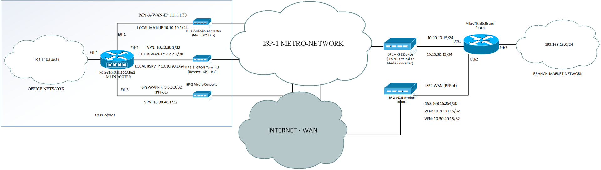
I will give a brief, simplified layout of the servers in Figure 1 below:

And a brief description of what we have:
After the introduction of Mikrotik into the network of routers, in the first of the stores, on the same day, an audit takes place there .
The organization of the work of the audit department is very interesting and distinctive. All stores have Wi-Fi access points with the same SSID and encryption keys. Thus, the revision TSDs have a static IP address from their separate pool (192.168.3.0/24).
Since the network was initially flat, any audit TSD when entering any of the stores turned out to be in a single flat network and connected to the audit server located anywhere without any problems.
The audit server was a RDP server with a special database. Which before the revision was synchronized with the main database server. The revision server also loaded the necessary files from the storage server. Terminals of data collection (TSD - Tablets), interacted mainly only with the server revision. However, sometimes, in extreme cases, when something went wrong on the revision server, they interacted directly with the RDP server located in the office. All other TSD (residing in stores and attached to them) interacted only with the main RDP server.
So, it seems to be clear and simple. There is a mobile group of devices, periodically walking from store to store and performing a terrible thing for the store employees - an audit.
She just needs to get a dynamic IP from the pool in the store and connect to the revision server located in the office or at least to the main RDP server.
However, as I was told by local system administrators, during the long years of the company's existence, during the times of audits, various cases occurred. One of which was a deliberate disruption of communications between the store and the main office in order for the audit to fail.
Therefore, historically, the audit server traveled along with the TSD from the office to the shops . Usually this happened in the evening on the eve of the audit day. The administrator brings the server to the store, connects it to any free port on any of the switches in the store (remember that the network is flat and all ports are connected by a single L2 domain). He puts the TSD on charge and leaves.
Further, at night, according to the schedule, the audit server connects to other servers located in the main office and performs various data synchronization and replication. It is important to note that the initiator of the connection is always the server of the revision.
We return to the implementation of a distributed segmented network in the first store. There will be installed a router that will separate the L2-segment from the general office, and also in case of which it will provide redundant communication channels of the provider.
Let me bring the image from the previous article so that it is clear what has changed in the store.
From the figure it is clear that the router installed in the store deprives the mobility of the audit group of devices.
Let me remind you what addressing looks like in stores after the introduction of routers:
Now, upon arrival at a specific store, the revision server, as before, connects to any free port in the switch, the TSD connects to a Wi-Fi access point. After that, the TSD can freely communicate with the revision server located with them geographically in the same store , but they cannot connect to the main RDP server in the office. And the revision server itself being out of the office, cannot synchronize data.
Since this was the first store to be translated, the entire network was not fully transferred to the new mode of operation. The schedule of the audit team has already been painted: today they are here, and tomorrow at another store, and then again here, etc.
An urgent solution is needed to ensure the connectivity of the audit team (the range of IP addresses is static: 192.168.3.0/24)
As already mentioned above, in this scheme , the synchronization initiator is the revision server itself: it connects to other servers and performs the tasks it needs. Revision TSD, if necessary , are also initializers of the RDP session with the main RDP server in the office.
My task is to provide IP connectivity of mobile devices located in any of the stores with an office. At the same time, device addressing remains unchanged. There is no option to get their DHCP addresses in a specific store.
Therefore, the first solution that occurred to me as a temporary (and it seems to remain permanent there) is the implementation of NAT.
I checked with the system administrators, is it true that none of the devices, except for the TSD by the employee of the audit department, need to connect to the audit server? The answer was no. However, sometimes it is necessary to connect remotely to programmers via RDP . However, they can do this by connecting to whatever may be from a PC in the store, and from it already connect to the server. Unless, of course, the PC in the store will be able to see the server.
So, we proceed to the implementation of the task.
First of all, I ask the administrators to set us all the audit TSD and on the server the address of the main gateway: 192.168.3.2
On the router located in the store, add this IP address on the interface looking towards the store:
Thus, this audit network (192.168.3.0/24) will be added to absolutely all stores , this will allow the mobile device group when moving between stores, without reconfiguring the parameters, to see the store's router , which means knowing where the devices are located in the office.
But, if we have 12 stores with the same addresses, how do servers in the office know where to send the packages?
Here, NAT comes to the rescue, the goal of which is to change the IP addresses from which the mobile group is accessing.
To do this, I find out which servers specifically require access by the mobile group devices and create a separate address-list for them:
Now, we make a rule for NAT translation to hide the addresses of the sources of the mobile group:
This NAT rule changes the source addresses (192.168.3.0) to the router addresses in transit networks (10.0.0.0/8) when accessing the necessary servers in the office.
So, the problem has already been partially solved, because Mobile group can freely come to any store, connect to the network, where it is already waiting for a pre-prepared gateway and initiate connections with the central office.
Let me remind you of this task I encountered on the first day of implementing the solution, and the network as a whole was not ready for changes , a situation arose: when the servers did not know anything about addressing between stores . And the gateway for them was the Kerio server, on which the route to the network of the store being translated was statically assigned to a separate, modestly standing Mikrotik router in the office.
Which later had to become the main router.
This means that in the office we needed to make another NAT broadcast in order to hide transit networks from the servers (which the mobile team is accessing) (10.0.0.0/8):
Similarly, in the store we add the address list
And also the translation rule:
As you can see, I had to honestly sign this rule - a crutch, because I had no other way to name this decision.
At this stage, the task of ensuring connectivity of the mobile device group with servers in the office from any store is completed.
Remote access to the server revision for programmers, if necessary, can be obtained by connecting to any PC in the store, which will go to the network 192.168.3.0/24 through the store's router, knowing about this network as its direct-connected network.
Since the introduction of the network into the first store and the transfer to this scheme of the last store, about 3 weeks have passed. At this time, minor bugs surfaced, which hastily corrected. In general, everything lived well, as planned. It's funny that after switching the first store to a new mode of operation, the ISP had an accident that left this store without connection and the system worked perfectly for switching to the reserve.
When the implementation took place in the last store, system administrators told me with uncertainty about another nuance that the management had set as a task to solve.
It turns out that among the mobile group there is an individual employee who also has a TSD from the range (192.168.3.0/24 ), with whom he goes to different shops, but his task is to re-evaluate goods whose shelf life is coming to an end.
From his TSD, he connects to the main RDP server located in the office and works with the database. Scans goods and prints new price tags.
Everything is good, the employee quietly comes to this or that store, clings to the Wi-Fi network as before, connects to the RDP server in the office without any problems, does what is necessary, starts printing to the printer, but ... The printer that prints the price tags mobile! Previously, the IP address in the 192.168.1.0/24 range and with a flat network with a single L2, remained available in any of the stores.
It also caused some inconvenience when connecting from the office to the audit server, one of the computers in the store where the audit took place was occupied by programmers due to the fact that the audit server was behind NAT, and access to it required to occupy one of the computers located in the store.
In general, I have a new task:
Well, now we are not going to get away from the implementation of the dynamic routing protocol, which I decided to leave in the first part.
Welcome to OSPF!
Here, though, I had to make another crutch again, since I wrote in the first article that OSPF packets did not pass through the ISP-1 network . Neither through multicast, nor through unicast, because CPE (xPON-terminals of Huawei) just dropped the protocol 89 .
Therefore, I decided to implement OSPF on tunnel interfaces that were intended primarily for redundancy.
OSPF in this situation is necessary for two things:
It turns out that we don’t have any need to transfer the entire network of the mobile group via OSPF (192.168.3.0/24), moreover, we cannot do this, because the re-evaluator and revision team are often located in different places, and connectivity must be with the north and with the Wi-Fi printer at the same time.
Therefore, I decided that the most optimal solution to this problem would be the transfer of more specific address / 32 specifically to these two devices - a printer and a server.
To do this, we need the following tools from the rich functionality of OSPF:
In the beginning, we will define the algorithm for how we will transfer information about the Wi-Fi printer and the server from the stores to the office.
For this, it is necessary for the OSPF protocol to know that these networks are connected to this router and to advertise these routes to the central router.
The OSPF protocol announces networks in two ways:
So, I decided to do the following:
It seems to be all clear, we proceed to implement.
We start OSPF processes on routers in shops and at office.
All stores will be in the same default area 0 .
Neighborhood states between OSPF routers will occur in tunnel interfaces , we have them between each store and office - 2.
On Mikrotik routers, the point-to-point cost of the interface defaults to - 10 . Since between each store and office we have 2 VPN channels, we set a cost of 20 on channel 2 .
We do similar actions on routers in stores plus, we point out the need to redistribute static routes, I decided to announce them as Type-1 :
In the given config, the commands responsible for the redistribution of static routes, such as type-1 , are given, this type is of higher priority than type-2 , and its metric is changed when it is announced between routers . Also, I specified two filters in the OSPF settings: ospf-in and ospf-out , these filters in Mikrotik play a role similar to those in Route-map in Cisco routers .
I propose to consider these filters:
The ospf-in filter filters any routes that can fly over OSPF to the router.
The ospf-out filter filters all possible routes that can be advertised through redistribution, with the exception of more-specific / 32 server routes and a Wi-Fi printer.
Now, it remains to add static / 32 routes for mobile devices, the location of which we need to know.
Please note that I add these static routes with the parameter = disabled = , that is, these routes will be disabled, inaccessible, and therefore will not fall into the announcement through OSPF .
Why? Because, if I add active routes at once in all stores, then on the main router they will be visible through all the stores, and we will return to the original one. When we do not know where exactly to catch a Wi-Fi printer , because These routes exist in all stores.
Therefore, static routes are turned off by default , and no one talks about them until the device actually appears in a particular store.
We can understand this by accessing the device via ping, and therefore we create two NetWatch rules with simple scripts:
These rules play a very simple role, which incidentally resembles the ip sla + track from the world of Cisco .
We ping the server and Wi-Fi printer every 10 seconds with a timeout of 2 seconds. If the ping is successful, we enable the static route , which instantly due to the redistribution goes to OSPF and the main router in the office finds out where the devices are located.
Thus, the Wi-Fi printer now prints again, as before, and programmers can work via RDP directly with the revision server. As if we still have a flat network.
The article was written six months later, after the final launch of the project to work in full. Over these six months, everything works perfectly and without failures. Wi-Fi printer is successfully caught, accidents at ISP unfortunately happen, but the shops no longer notice this.
The article again turned out great, thank you for your attention and patience. I will be glad to criticism and comments. If you have any questions, please answer.
In this article I want to share with you the solution of some additional tasks that appeared before me during the implementation of the project. Among such tasks was the organization of access to the servers in the office for devices of the employees of the audit department who move from store to store (Part 1). And also about how I caught a Wi-Fi shopping printer walking with OSPF dynamic routing protocol (Part 2).
As before, I hope that this solution will help someone from the beginners to solve similar problems. I will be glad to criticism from the professionals.
')
Who are interested in the title - I ask under the cat!
Part 0. What is given
Let me briefly recall what was done in the previous article. I was approached by the organization - a network of shopping stores with a request to organize a segmented network with the possibility of reservations and a limited budget.
I was assigned the task of making a network of a flat geographically distributed network in a city: a segmented network, with hierarchical addressing and, most importantly, with the possibility of reservation.
The connection between all the stores in the city is organized by the local ISP, by providing the enterprise with a separate VLAN within its network. Thus, the entire network in all stores and in the office was located in one large Layer2 Broadcast domain .
This model has several disadvantages:
- All devices on the network can see each other on Layer-2.
- The absence of any traffic filtering policies.
- A single Broadcast domain, the result of which is that any broadcast packet from each of the 400 devices, will be transmitted to all these 400 devices located in different parts of the city.
I will give a brief, simplified layout of the servers in Figure 1 below:
And a brief description of what we have:
- At the enterprise there are different servers performing different roles.
- There are special data collection terminals ( TSD ), in the figure I called them TABLETS.
- There are stationary TSD tied to a specific store and not leaving its limits. They have IP addresses from the device pool in the store.
- There are revision TSD and a separate server of revision with which they interact. These TSD constantly migrate from the store to the store where they perform the audit.
Part 1. "Oops, and we have a revision here"
After the introduction of Mikrotik into the network of routers, in the first of the stores, on the same day, an audit takes place there .
The organization of the work of the audit department is very interesting and distinctive. All stores have Wi-Fi access points with the same SSID and encryption keys. Thus, the revision TSDs have a static IP address from their separate pool (192.168.3.0/24).
Since the network was initially flat, any audit TSD when entering any of the stores turned out to be in a single flat network and connected to the audit server located anywhere without any problems.
The audit server was a RDP server with a special database. Which before the revision was synchronized with the main database server. The revision server also loaded the necessary files from the storage server. Terminals of data collection (TSD - Tablets), interacted mainly only with the server revision. However, sometimes, in extreme cases, when something went wrong on the revision server, they interacted directly with the RDP server located in the office. All other TSD (residing in stores and attached to them) interacted only with the main RDP server.
So, it seems to be clear and simple. There is a mobile group of devices, periodically walking from store to store and performing a terrible thing for the store employees - an audit.
She just needs to get a dynamic IP from the pool in the store and connect to the revision server located in the office or at least to the main RDP server.
However, as I was told by local system administrators, during the long years of the company's existence, during the times of audits, various cases occurred. One of which was a deliberate disruption of communications between the store and the main office in order for the audit to fail.
Therefore, historically, the audit server traveled along with the TSD from the office to the shops . Usually this happened in the evening on the eve of the audit day. The administrator brings the server to the store, connects it to any free port on any of the switches in the store (remember that the network is flat and all ports are connected by a single L2 domain). He puts the TSD on charge and leaves.
Further, at night, according to the schedule, the audit server connects to other servers located in the main office and performs various data synchronization and replication. It is important to note that the initiator of the connection is always the server of the revision.
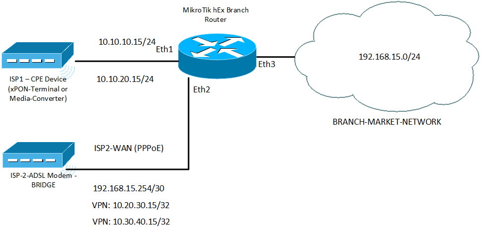
We return to the implementation of a distributed segmented network in the first store. There will be installed a router that will separate the L2-segment from the general office, and also in case of which it will provide redundant communication channels of the provider.
Let me bring the image from the previous article so that it is clear what has changed in the store.
From the figure it is clear that the router installed in the store deprives the mobility of the audit group of devices.
Let me remind you what addressing looks like in stores after the introduction of routers:
- 192.168.1.0/24 - central office network
- 192.168.2.0/24 - 192.168.13.0/24 local networks of each of the 12 stores
- 10.10.10.0/24 - the network coming to the main office through the main Ethernet channel
- 10.10.20.0/24 - the network coming to the main office through the backup channel (PON)
- 10.20.30.0/24 - a network inside a VPN, for stores clinging through an external network to IP from ISP-1
- 10.30.40.0/24 - a network inside a VPN, for shops clinging through an external network to IP from ISP-2
Now, upon arrival at a specific store, the revision server, as before, connects to any free port in the switch, the TSD connects to a Wi-Fi access point. After that, the TSD can freely communicate with the revision server located with them geographically in the same store , but they cannot connect to the main RDP server in the office. And the revision server itself being out of the office, cannot synchronize data.
Since this was the first store to be translated, the entire network was not fully transferred to the new mode of operation. The schedule of the audit team has already been painted: today they are here, and tomorrow at another store, and then again here, etc.
An urgent solution is needed to ensure the connectivity of the audit team (the range of IP addresses is static: 192.168.3.0/24)
As already mentioned above, in this scheme , the synchronization initiator is the revision server itself: it connects to other servers and performs the tasks it needs. Revision TSD, if necessary , are also initializers of the RDP session with the main RDP server in the office.
My task is to provide IP connectivity of mobile devices located in any of the stores with an office. At the same time, device addressing remains unchanged. There is no option to get their DHCP addresses in a specific store.
Therefore, the first solution that occurred to me as a temporary (and it seems to remain permanent there) is the implementation of NAT.
I checked with the system administrators, is it true that none of the devices, except for the TSD by the employee of the audit department, need to connect to the audit server? The answer was no. However, sometimes it is necessary to connect remotely to programmers via RDP . However, they can do this by connecting to whatever may be from a PC in the store, and from it already connect to the server. Unless, of course, the PC in the store will be able to see the server.
So, we proceed to the implementation of the task.
First of all, I ask the administrators to set us all the audit TSD and on the server the address of the main gateway: 192.168.3.2
On the router located in the store, add this IP address on the interface looking towards the store:
[s@VERTOLET-GW] > ip address export # jun/03/2016 21:22:19 by RouterOS 6.32.3 # /ip address add address=192.168.3.2/24 interface=bridge-VERTOLET network=192.168.3.0 Thus, this audit network (192.168.3.0/24) will be added to absolutely all stores , this will allow the mobile device group when moving between stores, without reconfiguring the parameters, to see the store's router , which means knowing where the devices are located in the office.
But, if we have 12 stores with the same addresses, how do servers in the office know where to send the packages?
Here, NAT comes to the rescue, the goal of which is to change the IP addresses from which the mobile group is accessing.
To do this, I find out which servers specifically require access by the mobile group devices and create a separate address-list for them:
[s@VERTOLET-GW] > ip firewall address-list export # jun/03/2016 21:32:00 by RouterOS 6.32.3 # /ip firewall address-list add address=192.168.1.2XX list=REVISION-Servers add address=192.168.1.2XX list=REVISION-Servers add address=192.168.1.2XX list=REVISION-Servers Now, we make a rule for NAT translation to hide the addresses of the sources of the mobile group:
[s@VERTOLET-GW] > ip firewall nat export # jun/03/2016 21:42:00 by RouterOS 6.32.3 /ip firewall nat add action=masquerade chain=srcnat comment=FROM-REVISION dst-address-list=REVISION-Servers src-address=192.168.3.0/24 This NAT rule changes the source addresses (192.168.3.0) to the router addresses in transit networks (10.0.0.0/8) when accessing the necessary servers in the office.
So, the problem has already been partially solved, because Mobile group can freely come to any store, connect to the network, where it is already waiting for a pre-prepared gateway and initiate connections with the central office.
Let me remind you of this task I encountered on the first day of implementing the solution, and the network as a whole was not ready for changes , a situation arose: when the servers did not know anything about addressing between stores . And the gateway for them was the Kerio server, on which the route to the network of the store being translated was statically assigned to a separate, modestly standing Mikrotik router in the office.
Which later had to become the main router.
This means that in the office we needed to make another NAT broadcast in order to hide transit networks from the servers (which the mobile team is accessing) (10.0.0.0/8):
Similarly, in the store we add the address list
[s@MAIN-BORDER-ROUTER] > ip firewall address-list export # jun/03/2016 21:52:12 by RouterOS 6.32.2 # /ip firewall address-list add address=192.168.1.2XX list=REVISION add address=192.168.1.2XX list=REVISION add address=192.168.1.2XX list=REVISION And also the translation rule:
[s@MAIN-BORDER-ROUTER] > ip firewall nat export # jun/03/2016 21:52:12 by RouterOS 6.32.2 # /ip firewall nat add action=masquerade chain=srcnat comment=NAT-KOSTUL-REVISION dst-address-list=REVISION src-address=10.0.0.0/8 As you can see, I had to honestly sign this rule - a crutch, because I had no other way to name this decision.
At this stage, the task of ensuring connectivity of the mobile device group with servers in the office from any store is completed.
Remote access to the server revision for programmers, if necessary, can be obtained by connecting to any PC in the store, which will go to the network 192.168.3.0/24 through the store's router, knowing about this network as its direct-connected network.
Part 2. My Wi-Fi printer refuses to print price tags!
Since the introduction of the network into the first store and the transfer to this scheme of the last store, about 3 weeks have passed. At this time, minor bugs surfaced, which hastily corrected. In general, everything lived well, as planned. It's funny that after switching the first store to a new mode of operation, the ISP had an accident that left this store without connection and the system worked perfectly for switching to the reserve.
When the implementation took place in the last store, system administrators told me with uncertainty about another nuance that the management had set as a task to solve.
It turns out that among the mobile group there is an individual employee who also has a TSD from the range (192.168.3.0/24 ), with whom he goes to different shops, but his task is to re-evaluate goods whose shelf life is coming to an end.
From his TSD, he connects to the main RDP server located in the office and works with the database. Scans goods and prints new price tags.
Everything is good, the employee quietly comes to this or that store, clings to the Wi-Fi network as before, connects to the RDP server in the office without any problems, does what is necessary, starts printing to the printer, but ... The printer that prints the price tags mobile! Previously, the IP address in the 192.168.1.0/24 range and with a flat network with a single L2, remained available in any of the stores.
It also caused some inconvenience when connecting from the office to the audit server, one of the computers in the store where the audit took place was occupied by programmers due to the fact that the audit server was behind NAT, and access to it required to occupy one of the computers located in the store.
In general, I have a new task:
- Provide the ability to print from the office to a mobile printer
- Provide the ability to connect to the server audit by RDP from the office directly
Well, now we are not going to get away from the implementation of the dynamic routing protocol, which I decided to leave in the first part.
Welcome to OSPF!
Here, though, I had to make another crutch again, since I wrote in the first article that OSPF packets did not pass through the ISP-1 network . Neither through multicast, nor through unicast, because CPE (xPON-terminals of Huawei) just dropped the protocol 89 .
Therefore, I decided to implement OSPF on tunnel interfaces that were intended primarily for redundancy.
OSPF in this situation is necessary for two things:
- Dynamically point the router at the office where to look for a Wi-Fi printer in order to transfer a small file to it for printing.
- Dynamically specify the router in the office where to look for the audit server, in order to transfer the RDP control commands there (the return traffic from the audit server to the office will go as intended in the first article)
It turns out that we don’t have any need to transfer the entire network of the mobile group via OSPF (192.168.3.0/24), moreover, we cannot do this, because the re-evaluator and revision team are often located in different places, and connectivity must be with the north and with the Wi-Fi printer at the same time.
Therefore, I decided that the most optimal solution to this problem would be the transfer of more specific address / 32 specifically to these two devices - a printer and a server.
To do this, we need the following tools from the rich functionality of OSPF:
- Point-to-point network-type
- Redistribution static routes
- Filtering
In the beginning, we will define the algorithm for how we will transfer information about the Wi-Fi printer and the server from the stores to the office.
For this, it is necessary for the OSPF protocol to know that these networks are connected to this router and to advertise these routes to the central router.
The OSPF protocol announces networks in two ways:
- Announcement of all networks belonging to the interface on which OSPF is enabled, if this interface is not Passive
- Announcement of networks, through redistribution of other dynamic routing protocols, directly connected routes, static routes
So, I decided to do the following:
- Starting the OSPF process in all stores and central router
- Creating static routes / 32 , for server and printer in all stores
- Filtering unnecessary static routes (and there are many of them) during redistribution and in OSPF
- Using NetWatch to track the actual availability of devices in a particular store and manage a static route
It seems to be all clear, we proceed to implement.
We start OSPF processes on routers in shops and at office.
All stores will be in the same default area 0 .
Neighborhood states between OSPF routers will occur in tunnel interfaces , we have them between each store and office - 2.
On Mikrotik routers, the point-to-point cost of the interface defaults to - 10 . Since between each store and office we have 2 VPN channels, we set a cost of 20 on channel 2 .
[s@KREDO-MAIN-BORDER-ROUTER] > routing ospf export # jun/03/2016 22:42:36 by RouterOS 6.32.2 # /routing ospf instance set [ find default=yes ] router-id=255.255.255.255 /routing ospf interface add cost=20 interface=2.VERTOLET-VPN-RESERVE network-type=point-to-point /routing ospf network add area=backbone network=10.20.30.0/24 add area=backbone network=10.30.40.0/24 We do similar actions on routers in stores plus, we point out the need to redistribute static routes, I decided to announce them as Type-1 :
[s@KREDO-VERTOLET-GW] > routing ospf export # jun/03/2016 22:50:17 by RouterOS 6.32.3 # /routing ospf instance set [ find default=yes ] redistribute-static=as-type-1 router-id=192.168.15.2 in-filter=ospf-in out-filter=ospf-out /routing ospf interface add cost=20 interface=VPN-OFFICE-RESERVE network-type=point-to-point add interface=VPN-OFFICE network-type=point-to-point /routing ospf network add area=backbone network=10.20.30.0/24 add area=backbone network=10.30.40.0/24 In the given config, the commands responsible for the redistribution of static routes, such as type-1 , are given, this type is of higher priority than type-2 , and its metric is changed when it is announced between routers . Also, I specified two filters in the OSPF settings: ospf-in and ospf-out , these filters in Mikrotik play a role similar to those in Route-map in Cisco routers .
I propose to consider these filters:
[s@VERTOLET-GW] routing filter export # jun/03/2016 23:01:57 by RouterOS 6.32.3 # /routing filter add action=discard chain=ospf-in ospf-type=external-type-1 add action=discard chain=ospf-in ospf-type=intra-area add action=accept chain=ospf-out prefix=192.168.3.3 protocol=static add action=accept chain=ospf-out prefix=192.168.3.252 protocol=static add action=discard chain=ospf-out protocol=static The ospf-in filter filters any routes that can fly over OSPF to the router.
The ospf-out filter filters all possible routes that can be advertised through redistribution, with the exception of more-specific / 32 server routes and a Wi-Fi printer.
Now, it remains to add static / 32 routes for mobile devices, the location of which we need to know.
[s@VERTOLET-GW] > ip route export # jun/03/2016 23:08:46 by RouterOS 6.32.3 # /ip route add comment=MOBILE-WiFi-PRINTER disabled=yes distance=1 dst-address=192.168.3.3/32 gateway=bridge-VERTOLET add comment=Revision-SERVER disabled=yes distance=1 dst-address=192.168.3.252/32 gateway=bridge-VERTOLET Please note that I add these static routes with the parameter = disabled = , that is, these routes will be disabled, inaccessible, and therefore will not fall into the announcement through OSPF .
Why? Because, if I add active routes at once in all stores, then on the main router they will be visible through all the stores, and we will return to the original one. When we do not know where exactly to catch a Wi-Fi printer , because These routes exist in all stores.
Therefore, static routes are turned off by default , and no one talks about them until the device actually appears in a particular store.
We can understand this by accessing the device via ping, and therefore we create two NetWatch rules with simple scripts:
[s@KREDO-VERTOLET-GW] >tool netwatch expoart # jun/03/2016 23:15:59 by RouterOS 6.32.3 # /tool netwatch add down-script="/ip route set [find comment=\"MOBILE-WiFi-PRINTER\"] disable=yes" host=192.168.3.3 interval=10s timeout=2s up-script="/ip route set [find comment=\"MOBILE-WiFi-PRINTER\"] disable=no" add down-script="/ip route set [find comment=\"Revision-SERVER\"] disable=yes" host=192.168.3.252 interval=10s timeout=2s up-script="/ip route set [find comment=\"Revision-SERVER\"] disable=no" These rules play a very simple role, which incidentally resembles the ip sla + track from the world of Cisco .
We ping the server and Wi-Fi printer every 10 seconds with a timeout of 2 seconds. If the ping is successful, we enable the static route , which instantly due to the redistribution goes to OSPF and the main router in the office finds out where the devices are located.
Thus, the Wi-Fi printer now prints again, as before, and programmers can work via RDP directly with the revision server. As if we still have a flat network.
The article was written six months later, after the final launch of the project to work in full. Over these six months, everything works perfectly and without failures. Wi-Fi printer is successfully caught, accidents at ISP unfortunately happen, but the shops no longer notice this.
The article again turned out great, thank you for your attention and patience. I will be glad to criticism and comments. If you have any questions, please answer.
Source: https://habr.com/ru/post/302580/
All Articles