Reflection of the dynamics in the access control model
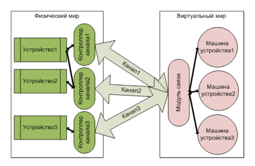
In the previous article , the structural model of access control systems was considered as a combination of the roles of objects and double bonds between them. This model allows you to reflect the results of all processes of interest to us that occur in the system. Processes in the system are expressed through the interaction of objects, and the results of interactions are stored in the links. It can be said that connections are the memory of interactions, but the interaction processes themselves are not reflected in any way in the structural model. The observer sees the interaction through changes in behavior or changes in the state of objects, which we will call devices. For example, when you bring a card with an RFID tag to the reader, the latter informs you to read the LED with a sound signal and blink. This can be interpreted as a change in the state of the physical reader, while the interaction between the card and the reader itself, the reading itself, is not considered. It is assumed that the reader passes through a series of discrete states. Such discrete states are conveniently simulated using state machines, but for this you need to establish a channel between the physical world and the virtual world (computer model). Such a channel, controlled by the channel controller, transmits physical signals from the device, which are converted by a special communication module into signals that control the machine of the device states. The channel can be two-way:

One device can be connected to several channels and one channel can be connected to several devices, while one communication module can serve all channels:
')
We call devices objects whose behavior can be described by a set of discrete states of states modeled by machines. The determination of the state set for each device is carried out by the designer of the simulated system.
In the implemented access control system, two readers were used. One reader was installed on the turnstile, and the second on the card reader. With this arrangement of readers, a single-pass visitor can leave the access zone only when returning the card through the card reader: the card reader will generate the status of the label Exit allowed, and the reader on the turnstile - Exit prohibited. Both readers are served by two channels, one channel receives information about the name of the reader, and the second about the name of the card.
Therefore, the reader has the following discrete states:

Using a separate state The names of the reader and the card are obtained instead of combining it with the initial state due to the fact that the reader is part of the system. In this case, the return to the initial state will be carried out by a signal from the turnstile.
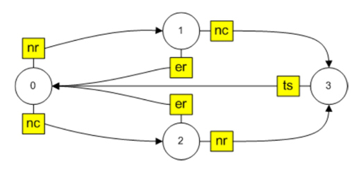
Transition to these states is carried out when one of the signals is received: the reader's name is determined, the card's name is determined, a transition is made or a timer has been triggered (a signal from the turnstile machine), an error has been received. For example, we denote these signals as follows: the reader's name is defined - nr, the card's name is defined - nc, the signal from the turnstile is received - ts, the error is received - er. Since in the general case it is not known what will be determined earlier - the name of the reader or card, the state machine with signals and the corresponding transitions will look like:
The machine is implemented very simply: since the new state is uniquely determined by the current state and the signal, then the text state-signal is taken as the key determining the transition. Knowing the initial state and the new state, it is easy to determine the transition, which will be set by the text value current_state #new_state . Then for the reader’s machine we get the following correspondences between the key and the new state, as well as the transition:
In other words, signals and transitions in the reader's state machine are fully described by the vector gen
The algorithm of the state machine is completely obvious (the initial state is set when the program is started):

All actions that occur when a state changes, are performed only on transitions by the corresponding scripts. For the reader's machine, these actions are shown in the table:
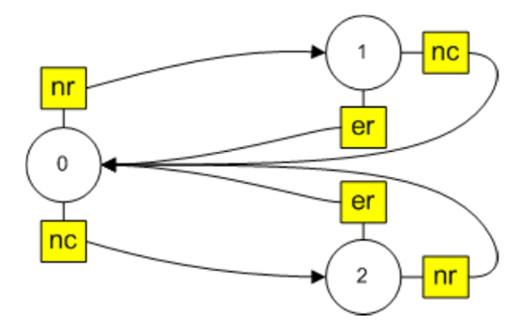
The above machine is used in the case when the reader is working in the visitor card identification mode to go through the turnstile. In the implemented access control system, the card reader can work in the mode of registering a new visitor (new card). In this case, there is no interaction between it and the turnstile, and the reduced machine will not work, as it will not be able to exit from state 3. In order for the machine in registration mode to determine the reader’s number and card number to return to its initial state, it must be replaced with the following:
But what about the fact that from states 1 and 2 you can go through two different transitions (on these transitions different actions are carried out)? We give the transitions the names (in the picture they are indicated in a diamond)
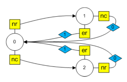
For example, between states 1 and 0 there are two transitions on the signal nc and on the signal er. For a single transition, it had the name 1 # 0, for several transitions we will use the names current_ state # transition_name # new_ state .
In order to be able to use the algorithm given above, we change the rule for the formation of a state name in gen [1]: transition_name # new_state_name . Then the vector gen, defining the behavior of the machine will have the form:
The minimal changes in the algorithm are associated with the definition of a new state, since nState = gen [1] [keyInd] does not contain the name of the new state, but its combination with the name of the transition, but it is clear how to find it.
The machine in the registration mode at the crossings performs other actions, it does not communicate with the turnstile
The turnstile is a "complex" device, in which there are two locks and the device fixing the transition, usually a reed switch. There are warning lights showing the status of the locks and possibly the source of the sound. We call one lock as an entrance, and another as an exit. Since each lock can be in one of two states (open / closed), the turnstile can have the following states:

The turnstile is controlled by the reader's commands, the commands of the control device (in our case, the touchscreen of the tablet), as well as the signal of the reed switch. In addition, in order to prevent the system from “freezing” in case of a failure of the transition (the reader worked, the lock opened, and the visitor did not pass), a timer was added to the system, which also affects the transitions in the turnstile's car.
Transition to these states is carried out when one of the signals is received: open the input, open the output (from the reader), close the input / output (from the reed switch - turnstile), open / close the input / output (from the touchscreen), close the input / output (from the timer) ):
The state machine of the turnstile with the signals and transitions shown in the table will look like:
The turnstile machine performs the following actions at the transitions:
The built turnstile machine allows one-way passage in any direction when registering a card with a permanent or temporary status on the reader of the turnstile and exit of a visitor with a card with a one-time status only through its registration on the reader of the card reader. It is also possible to control the turnstile from the tablet (clicking on the arrow 1 opens the entrance, and 2 - the exit. Closing occurs by the signals of the reed switch and timer):
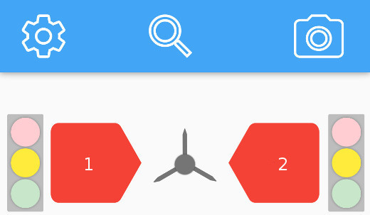
At the same time, occasionally there are cases when it is necessary to open or close an entry / exit via a button regardless of the presence of a card. To do this, use the "traffic lights" on the left (entrance) and on the right (exit). Cards at the entrance or exit work only when the corresponding traffic light "lit" yellow light. The red signal closes the corresponding lock and cannot be opened with any card, and the green one, on the contrary, opens and neither the reed switch nor the timer can close it.
And now the question arises: if, when you press the green button of the traffic light, we open the entrance, i.e. we make the transition to state 1 in the turnstile machine, then how to prevent the transition to state 0 by the signal of the reed switch gt or timer tt? It is clear that with the “machine” approach, I do not want to consider working with flags, etc., but I want to work with the machine given by the gen vector.
Expand the concept of a key in the vector gen. Add a value to the key line to form, which we will call the condition, that is, the key is the state_signal + condition. We define the following values of the condition depending on which light “lights up” at traffic lights and which key will be for the signals from the reed switch gt and the timer tt in state 1:
Now we know the answer to the question. After opening the entrance with the green button of the left traffic light, the signal from the reed switch will create the key 1_gtIs, and the signal from the timer - 1_ttIs, which are not in the gen vector and therefore no transition will occur. Turnstile will remain in state 1.
Consider additional transitions in the car turnstile associated with clicking on the buttons of traffic lights. The signals from the traffic light of the entrance are denoted by lr - red, ly-yellow, lg - green, and from the traffic light exit - rr - red, ry-yellow, rg - green.
The corresponding transitions in the state machine:
Full vector gen for the turnstile machine:
Actions on additional transitions are clear from the signal transcripts.
The turnstiles can be controlled from the tablet and vice versa, the state of the interface depends on the signals from the reader and the turnstile.
As can be seen from the initial state of the interface (figure above), two buttons in the form of arrows and three buttons at each traffic light are used for control. The arrows work only when the yellow light at the corresponding traffic light. If the traffic light is red or green, then the arrow does not work. In other words, the traffic light has a status of on and off. Also, the arrows have two of the same states.
As a result, we get the following possible interface states:

Let us collect, as before, all signals and transitions in the table (we indicate the signals belonging only to the left half of the diagram, and we give the gen vector completely).
The corresponding transitions in the car:

The full vector gen for the interface state machine:
Actions on transitions are illustrated by interface states.

In addition, the condition for the turnstile's car changes on the transitions and it is called up (signals ep, xp, lr, lg, ly, rr, rg, ry):
Thus, we built with the help of three state machines that are synchronized using signal exchanges, a simple dynamic model of the ACS, which allows for the implementation of a rather complex control system.
In the future, a living example of the implementation of an ACS based on the principles set forth in this and previous articles will be given.
One device can be connected to several channels and one channel can be connected to several devices, while one communication module can serve all channels:
')
Devices in the model ACS
We call devices objects whose behavior can be described by a set of discrete states of states modeled by machines. The determination of the state set for each device is carried out by the designer of the simulated system.
Reader State Machine
In the implemented access control system, two readers were used. One reader was installed on the turnstile, and the second on the card reader. With this arrangement of readers, a single-pass visitor can leave the access zone only when returning the card through the card reader: the card reader will generate the status of the label Exit allowed, and the reader on the turnstile - Exit prohibited. Both readers are served by two channels, one channel receives information about the name of the reader, and the second about the name of the card.
Therefore, the reader has the following discrete states:
- the reader is ready to receive signals;
- Reader name received;
- card name received;
- obtained reader and card names.
Using a separate state The names of the reader and the card are obtained instead of combining it with the initial state due to the fact that the reader is part of the system. In this case, the return to the initial state will be carried out by a signal from the turnstile.
Transition to these states is carried out when one of the signals is received: the reader's name is determined, the card's name is determined, a transition is made or a timer has been triggered (a signal from the turnstile machine), an error has been received. For example, we denote these signals as follows: the reader's name is defined - nr, the card's name is defined - nc, the signal from the turnstile is received - ts, the error is received - er. Since in the general case it is not known what will be determined earlier - the name of the reader or card, the state machine with signals and the corresponding transitions will look like:
The machine is implemented very simply: since the new state is uniquely determined by the current state and the signal, then the text state-signal is taken as the key determining the transition. Knowing the initial state and the new state, it is easy to determine the transition, which will be set by the text value current_state #new_state . Then for the reader’s machine we get the following correspondences between the key and the new state, as well as the transition:
| condition | Signal | Signal decoding | Key | condition | Transition |
| 0 | nr | Reader name | 0_nr | one | 0 # 1 |
| 0 | nc | Card name | 0_nc | 2 | 0 # 2 |
| one | nc | Card name | 1_nc | 3 | 1 # 3 |
| one | er | Mistake | 1_er | 0 | 1 # 0 |
| 2 | nr | Reader name | 2_nr | 3 | 2 # 3 |
| 2 | er | Mistake | 2_er | 0 | 2 # 0 |
| 3 | ts | Turnstile signal | 3_ts | 0 | 3 # 0 |
In other words, signals and transitions in the reader's state machine are fully described by the vector gen
gen=[[0_nr, 0_nc, 1_nc, 1_er, 2_nr, 2_er, 3_ts], [1, 2, 3, 0, 3, 0, 0]] The algorithm of the state machine is completely obvious (the initial state is set when the program is started):
All actions that occur when a state changes, are performed only on transitions by the corresponding scripts. For the reader's machine, these actions are shown in the table:
| Transition | Actions |
| 0 # 1 | Determining the name of the reader in the system |
| 0 # 2 | Determining the name of the card in the system |
| 1 # 3, 2 # 3 | Turnstile machine call (eo, xo signals) |
| 1 # 0, 2 # 0, 3 # 0 | No action |
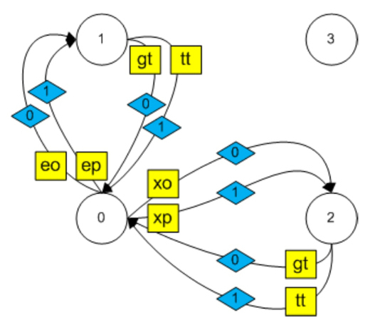
The above machine is used in the case when the reader is working in the visitor card identification mode to go through the turnstile. In the implemented access control system, the card reader can work in the mode of registering a new visitor (new card). In this case, there is no interaction between it and the turnstile, and the reduced machine will not work, as it will not be able to exit from state 3. In order for the machine in registration mode to determine the reader’s number and card number to return to its initial state, it must be replaced with the following:
But what about the fact that from states 1 and 2 you can go through two different transitions (on these transitions different actions are carried out)? We give the transitions the names (in the picture they are indicated in a diamond)
For example, between states 1 and 0 there are two transitions on the signal nc and on the signal er. For a single transition, it had the name 1 # 0, for several transitions we will use the names current_ state # transition_name # new_ state .
| condition | Signal | Signal decoding | Key | condition | Transition |
| 0 | nr | Reader name | 0_nr | one | 0 # 1 |
| 0 | nr | Card name | 0_nc | 2 | 0 # 2 |
| one | nc | Card name | 1_nc | 0 | 1 # 0 # 0 |
| one | er | Mistake | 1_er | 0 | 1 # 1 # 0 |
| 2 | nr | Reader name | 2_nr | 0 | 2 # 0 # 0 |
| 2 | er | Mistake | 2_er | 0 | 2 # 1 # 0 |
In order to be able to use the algorithm given above, we change the rule for the formation of a state name in gen [1]: transition_name # new_state_name . Then the vector gen, defining the behavior of the machine will have the form:
gen=[[0_nr, 0_nc, 1_nc, 1_er, 2_nr, 2_er], [1, 2, 0#0, 1#0, 0#0, 1#0]] The minimal changes in the algorithm are associated with the definition of a new state, since nState = gen [1] [keyInd] does not contain the name of the new state, but its combination with the name of the transition, but it is clear how to find it.
The machine in the registration mode at the crossings performs other actions, it does not communicate with the turnstile
| Transition | Actions |
| 0 # 1 | Determining the name of the reader in the system |
| 0 # 2 | Determining the name of the card in the system |
| 1 # 0 # 0, 2 # 0 # 0 | Record new data |
| 1 # 1 # 0, 2 # 1 # 0 | Error message |
Turnstile status machine
The turnstile is a "complex" device, in which there are two locks and the device fixing the transition, usually a reed switch. There are warning lights showing the status of the locks and possibly the source of the sound. We call one lock as an entrance, and another as an exit. Since each lock can be in one of two states (open / closed), the turnstile can have the following states:
The turnstile is controlled by the reader's commands, the commands of the control device (in our case, the touchscreen of the tablet), as well as the signal of the reed switch. In addition, in order to prevent the system from “freezing” in case of a failure of the transition (the reader worked, the lock opened, and the visitor did not pass), a timer was added to the system, which also affects the transitions in the turnstile's car.
Transition to these states is carried out when one of the signals is received: open the input, open the output (from the reader), close the input / output (from the reed switch - turnstile), open / close the input / output (from the touchscreen), close the input / output (from the timer) ):
| condition | Signal | Signal decoding | Key | condition | Transition |
| 0 | eo | Open input (reader) | 0_eo | one | 0 # 0 # 1 |
| 0 | xo | Open output (reader) | 0_xo | 2 | 0 # 0 # 2 |
| 0 | ep | Open Entry (touchscreen) | 0_ep | one | 0 # 1 # 1 |
| 0 | xp | Open exit (touchscreen) | 0_xp | 2 | 0 # 1 # 2 |
| one | gt | Close entrance (reed switch) | 1_gt | 0 | 1 # 0 # 0 |
| one | tt | Close Entry (Timer) | 1_tt | 0 | 1 # 1 # 0 |
| 2 | gt | Close exit (reed switch) | 2_gt | 0 | 2 # 0 # 0 |
| 2 | tt | Close exit (timer) | 2_tt | 0 | 2 # 1 # 0 |
The state machine of the turnstile with the signals and transitions shown in the table will look like:
The turnstile machine performs the following actions at the transitions:
| Transition | Actions |
| 0 # 0 # 1, 0 # 1 # 1 | Opening the input, turning on the timer, calling the interface machine (eo signal) |
| 0 # 0 # 2, 0 # 1 # 2 | Opening the output, turning on the timer, calling the interface machine (signal eo) |
| 1 # 0 # 0 | Closing the input, recording data in communications, calling the reader’s machine (ts signal), calling the interface machine (ts signal) |
| 1 # 1 # 0 | Closing the input, calling the reader’s machine (ts signal), calling the interface machine (ts signal) |
| 2 # 0 # 0 | Closing the output, recording data in communications, calling the reader’s machine (ts signal), calling the interface machine (ts signal) |
| 2 # 1 # 0 | Closing the output, calling the reader’s machine (ts signal), calling the interface machine (ts signal) |
The built turnstile machine allows one-way passage in any direction when registering a card with a permanent or temporary status on the reader of the turnstile and exit of a visitor with a card with a one-time status only through its registration on the reader of the card reader. It is also possible to control the turnstile from the tablet (clicking on the arrow 1 opens the entrance, and 2 - the exit. Closing occurs by the signals of the reed switch and timer):
At the same time, occasionally there are cases when it is necessary to open or close an entry / exit via a button regardless of the presence of a card. To do this, use the "traffic lights" on the left (entrance) and on the right (exit). Cards at the entrance or exit work only when the corresponding traffic light "lit" yellow light. The red signal closes the corresponding lock and cannot be opened with any card, and the green one, on the contrary, opens and neither the reed switch nor the timer can close it.
And now the question arises: if, when you press the green button of the traffic light, we open the entrance, i.e. we make the transition to state 1 in the turnstile machine, then how to prevent the transition to state 0 by the signal of the reed switch gt or timer tt? It is clear that with the “machine” approach, I do not want to consider working with flags, etc., but I want to work with the machine given by the gen vector.
Expand the concept of a key in the vector gen. Add a value to the key line to form, which we will call the condition, that is, the key is the state_signal + condition. We define the following values of the condition depending on which light “lights up” at traffic lights and which key will be for the signals from the reed switch gt and the timer tt in state 1:
| Traffic light | Traffic light color | Condition | Key |
| Both traffic lights | Yellow | 1_gt, 1_tt | |
| Entry only | Not yellow (red or green) | ls | 1_gtIs, 1_ttIs |
| Exit only | Not yellow (red or green) | rs | 1_gtrs, 1_ttrs |
| Both traffic lights | Not yellow (red or green) | bs | 1_gtbs, 1_ttbs |
Now we know the answer to the question. After opening the entrance with the green button of the left traffic light, the signal from the reed switch will create the key 1_gtIs, and the signal from the timer - 1_ttIs, which are not in the gen vector and therefore no transition will occur. Turnstile will remain in state 1.
Consider additional transitions in the car turnstile associated with clicking on the buttons of traffic lights. The signals from the traffic light of the entrance are denoted by lr - red, ly-yellow, lg - green, and from the traffic light exit - rr - red, ry-yellow, rg - green.
| condition | Signal | Signal decoding | Key | condition | Transition |
| 0 | lg | Open the entrance with the green button of the traffic light | 0_lg, 0_lgls, 0_lgrs, 0_lgbs | one | 0 # 2 # 1 |
| one | lr, ly | Close entrance with red or yellow traffic light button | 1_lrls, 1_lrbs, 1_lyls, 1_lybs | 0 | 1 # 2 # 0 |
| 0 | rg | Open the exit with the green button | 0_rg, 0_rgls, 0_rgrs, 0_rgbs | 2 | 0 # 2 # 2 |
| 2 | ry, rr | Close exit red or yellow button traffic lights | 2_ryrs, 2_rrrs, 2_ryrs, 2_rrbs | 0 | 2 # 2 # 0 |
| one | rg | Open the exit with the green button of the traffic light (with open entrance) | 1_rgls, 1_rgbs | 3 | 1 # 2 # 3 |
| 2 | lg | Open the entrance with the green button of the traffic light (with the exit open) | 2_lgrs, 2_lgbs | 3 | 2 # 2 # 3 |
| 3 | lr, ly | Close entrance with red or yellow traffic light button | 3_lybs, 3_lrbs | one | 3 # 2 # 1 |
| 3 | ry, rr | Close exit red or yellow button traffic lights | 3_rybs, 3_rrbs | 2 | 3 # 2 # 2 |
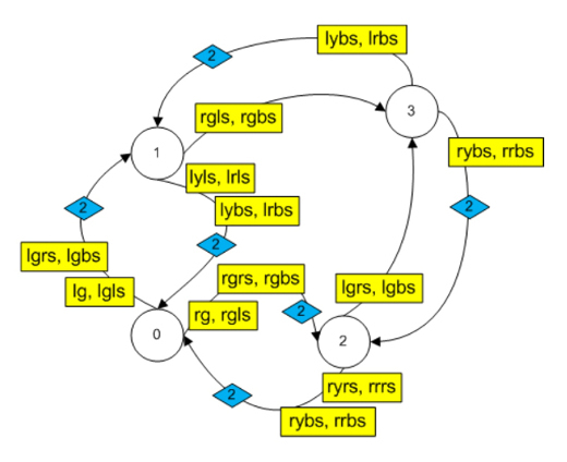
The corresponding transitions in the state machine:
Full vector gen for the turnstile machine:
gen=[[0_eo, 0_xo, 0_ep, 0_xp, 1_gt, 1_tt, 2_gt, 2_tt, 0_lg, 0_lgls, 0_lgrs, 0_lgbs, 1_lrls, 1_lrbs, 1_lyls, 1_lybs, 0_rg, 0_rgls, 0_rgrs, 0_rgbs, 2_ryrs, 2_rrrs, 2_ryrs, 2_rrbs, 1_rgls, 1_rgbs, 2_lgrs, 2_lgbs, 3_lybs, 3_lrbs, 3_rybs, 3_rrbs, 1_xols, 1_xpls, 3_gtls, 3_ttls, 2_eors, 2_eprs, 3_gtrs, 3_ttrs], [0#1, 0#2, 1#1, 1#2, 0#0,1#0, 0#0, 1#0, 2#1, 2#1, 2#1, 2#1, 2#0, 2#0, 2#0, 2#0, 2#2, 2#2, 2#2, 2#2, 2#0, 2#0, 2#0, 2#0, 2#3, 2#3, 2#3, 2#3, 2#1, 2#1, 2#2, 2#2, 0#3, 1#3, 0#1, 1#1, 0#3, 1#3, 0#2, 1#2]]. Actions on additional transitions are clear from the signal transcripts.
Interface State Machine
The turnstiles can be controlled from the tablet and vice versa, the state of the interface depends on the signals from the reader and the turnstile.
As can be seen from the initial state of the interface (figure above), two buttons in the form of arrows and three buttons at each traffic light are used for control. The arrows work only when the yellow light at the corresponding traffic light. If the traffic light is red or green, then the arrow does not work. In other words, the traffic light has a status of on and off. Also, the arrows have two of the same states.
As a result, we get the following possible interface states:
- everything is off. We are waiting for the button;
- arrow entry is enabled;
- arrow-out enabled;
- traffic lights are on;
- traffic lights are turned on;
- both traffic lights are on;
- the arrow-exit is on when the traffic light is on;
- The arrow-in is turned on when the traffic light is on.
Let us collect, as before, all signals and transitions in the table (we indicate the signals belonging only to the left half of the diagram, and we give the gen vector completely).
| condition | Signal | Signal decoding | Key | condition | Transition |
| 0 | ae | Click on the arrow entrance | 0_ae | one | 0 # 0 # 1 |
| 0 | eo | Open input (reader) | 0_eo | one | 0 # 1 # 1 |
| one | ts | Close entrance (turnstile) | 1_ts | 0 | 1 # 0 |
| 0 | lr | Press the red signal of the traffic light entrance | 0_lr | 3 | 0 # 0 # 3 |
| 0 | lg | Press the green signal of the traffic light entrance | 0_lg | 3 | 0 # 1 # 3 |
| 3 | lr | Press the red signal of the traffic light entrance | 3_lr | 3 | 3 # 0 # 3 |
| 3 | lg | Press the green signal of the traffic light entrance | 3_lg | 3 | 3 # 1 # 3 |
| 3 | ly | Press the yellow signal of the traffic light-input | 3_ly | 0 | 3 # 0 |
| 3 | rr | Press the red signal to exit | 3_rr | five | 3 # 0 # 5 |
| 3 | rg | Press the green signal to exit | 3_rg | five | 3 # 1 # 5 |
| 3 | ax | Click on the exit arrow | 3_ax | 6 | 3 # 0 # 6 |
| 3 | xo | Open output (reader) | 3_xo | 6 | 3 # 1 # 6 |
| five | ry | Press the yellow signal to exit | 5_ry | 3 | 5 # 3 |
| 6 | ts | Close entrance (turnstile) | 6_ts | 3 | 6 # 3 |
The corresponding transitions in the car:
The full vector gen for the interface state machine:
gen=[[0_ae, 0_eo, 0_ax, 0_ex, 1_ts, 2_ts, 0_lr, 0_lg, 0_rr, 0_rg, 3_ly, 4_ry, 3_ax, 3_xo, 6_ts, 4_ae, 4_eo, 7_ts, 3_lr, 3_lg, 3_rr, 3_rg, 4_rr, 4_rg, 4_lr, 4_lg, 5_ry, 5_ly, 5_lr, 5_lg, 5_rr, 5_rg], [0#1, 1#1, 0#2, 1#2, 0, 0, 0#3, 1#3, 0#4, 1#4, 0, 0, 0#6, 1#6, 3, 0#7, 1#7, 4, 0#3, 1#3, 0#5, 1#5, 0#4, 1#4, 0#5, 1#5, 3, 4, 0#5, 1#5, 2#5, 3#5]] Actions on transitions are illustrated by interface states.
In addition, the condition for the turnstile's car changes on the transitions and it is called up (signals ep, xp, lr, lg, ly, rr, rg, ry):
| Transition | Condition |
| 0 # 0 # 3.0 # 1 # 3 | ls |
| 3 # 0 | |
| 3 # 0 # 5.3 # 1 # 5 | bs |
| 5 # 3 | ls |
| 0 # 0 # 4.0 # 1 # 4 | rs |
| 4 # 0 | |
| 4 # 0 # 5.4 # 1 # 5 | bs |
| 5 # 4 | rs |
Thus, we built with the help of three state machines that are synchronized using signal exchanges, a simple dynamic model of the ACS, which allows for the implementation of a rather complex control system.
In the future, a living example of the implementation of an ACS based on the principles set forth in this and previous articles will be given.
Source: https://habr.com/ru/post/302226/
All Articles