New release candidate for CAD system Qucs-0.0.19S-RC6
Qucs is a cross-platform (Linux, Windows, MacOS-X) open source electronic circuit simulator. My previous articles on Habré tell about it:
- Qucs - open-source CAD for modeling electronic circuits habrahabr.ru/post/248005
- Qucs project news: preparation for release 0.0.19 habrahabr.ru/post/259193
- Qucs project news: release candidate available with support for circuit modeling in SPICE habrahabr.ru/post/263555
')
Currently, two versions of Qucs are being prepared for release in parallel:
- Qucs - assemblies with the usual set of functions. Only the Qucsator simulation engine is used.
- QucsS is an assembly with the option of using SPICE (supported by the Ngspice , XYCE , SpiceOpus engines ) as the default simulation engine. These assemblies contain the letter “S” after the version number. Of greatest interest to engineers is Ngspice.
While the next release of Qucs is again postponed indefinitely, a release candidate for Qucs-0.0.19S-RC6 with SPICE support has been released. This release candidate is significantly different from all previous ones. Download packages for the two platforms (Windows and Linux) here: github.com/ra3xdh/qucs/releases/tag/0.0.19S-rc6
Under the cat will be discussed about the innovations in this release candidate.
Installation
Linux
The installation procedure for Linux has not changed. You need to build a package from source. Requires compilers and Qt4 for developers. Qucs and the Qucsator simulation engine need to be built separately:
tar xvfz qucs-0.0.19S-rc6.tar.gz cd qucs-0.0.19S-rc6 cd qucs ./configure make make install cd ../qucs-core ./configure make make install In this case, everything will be put into / usr / local, and if a previous version of Qucs is already installed there, then it will be overwritten. To install QucsS in another directory, you need to change the configure command:
./configure --prefix=/some_qucs_location/ If only SPICE is required, then only the Qucs interface can be built:
tar xvfz qucs-0.0.19S-rc6.tar.gz cd qucs-0.0.19S-rc6/qucs ./configure --prefix=/some-qucs-location/ make make install Ngspice should be installed using the package manager. It is in all modern distributions.
When you first start QucsS will ask for the default simulator.
Windows
For Windows, you should download the binary installer. In conjunction with QucsS, it is recommended to use a special Ngspice assembly, which can also be downloaded from the release page. Building Ngspice, the project downloaded from the official site will work, but it does not allow to write logs, since has a non-switchable GUI.
Overview of the new features Qucs-0.0.19S-RC6
In addition to fixing bugs and synchronizing with the code base of the main project, QucsS contains a number of very important new features.
Set the default simulator
The simulation startup procedure using the SPICE simulator has changed. Now you can assign a default simulator that will run every time the user calls a simulation (for example, by pressing F2). Use the special menu item Simulate with SPICE is no longer necessary. If one of the SPICE engines is selected, then the program no longer requires the Qucsator engine and full installation.
The default simulator can be assigned either when the program is first launched, or after selecting Simulation-> Select default simulator in the main menu. If one of the SPICE engines is selected, components and libraries incompatible with it are not shown. The default setup dialog for the simulator looks like this:

The default simulator should be selected in the drop-down list at the top of the window. Windows users also need to specify the correct path to the executable files of simulators.
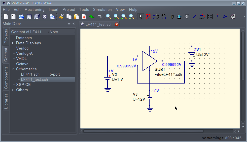
Calculating the operating point with Ngspice
The calculation of the operating point for direct current (by pressing F8) for SPICE engines has been implemented. Now, if Ngspice is assigned as the default simulator, then it will calculate the operating point. The calculation results look like this:
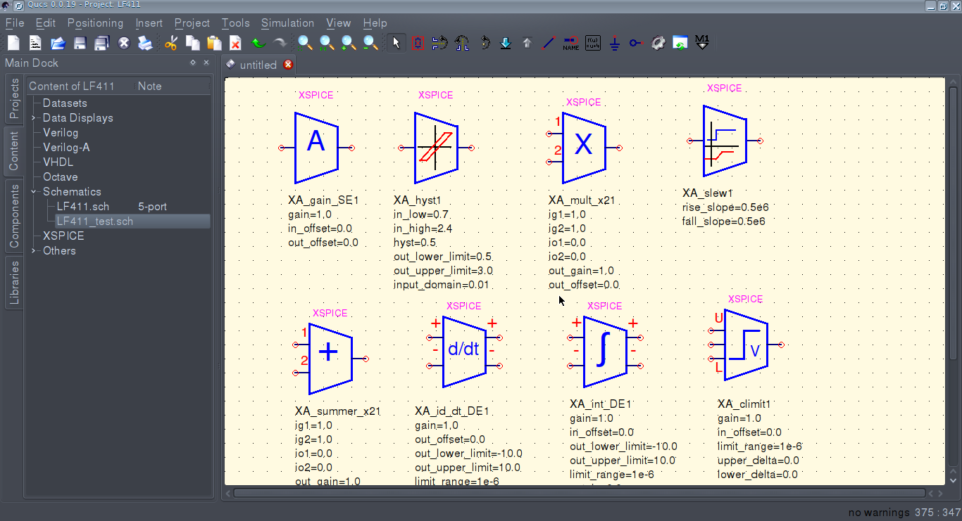
New set of analog blocks XPSPICE
Components XSPICE rendered in a special library Xanalogue. XSPICE allows you to use components that simulate the scheme at the block level. The new library contains models of amplifiers, adders, multipliers, dividers, integrators, limiters, etc. Here's what they look like:
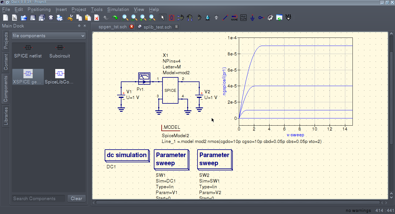
SPICE directives .MODEL and .INCLUDE
In addition to the existing SPICE-compatible semiconductor components, the ability to place the .MODEL and .INCLUDE directives on the circuit is added, which allows the use of unmodified libraries of semiconductor components in the circuit. The .INCLUDE directive allows you to refer to the library, and the .MODEL directive allows you to copy the SPICE model line by line and inject it into the schema. A field effect transistor mixer circuit illustrates the use of this directive.

Transformer and Core Models
Added components that allow you to simulate transformers and coils with a ferromagnetic core. There is a Transformers library containing transformers and a Cores library with core models (mostly steel cores). This functionality is available only through Ngspice. The figure shows a diagram of lamp ULF (on a 66 lamp), which illustrates the use of new library models of transformers and SPICE models.
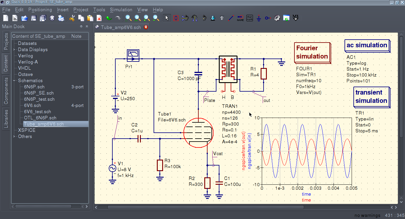
You can create your own transformers using a combination of Icouple components (winding) and Core (core). Ideal transformers can be created using the “K coupling” component.

Creating non-standard SPICE components
Two components “SPICE generic device” and “XSPICE generic device” are added. They allow you to create a new non-standard component, knowing only the number of pins and the letter assigned to it in SPICE. This is useful if the component has already been added to the engine, and the GUI is late. This is especially true of the XYCE simulator, where new components are added in each release. On the enclosed scheme, a conventional field effect transistor is declared as a non-standard component. The field-effect transistor model is connected using the .MODEL directive.
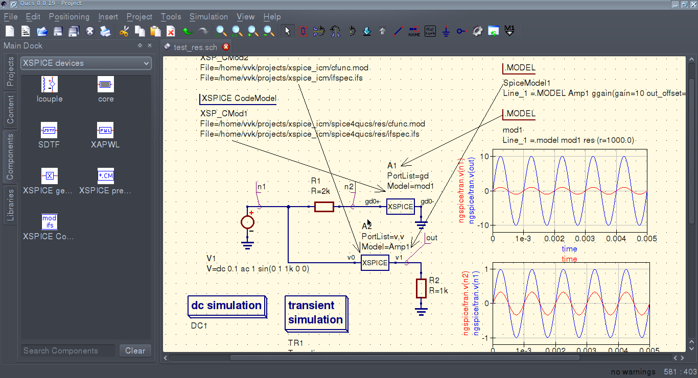
XSPICE CodeModel Support
Added support for the model description language of analog components XSPICE CodeModel (known since 1991). It allows you to create new models and connect them to the Ngspice simulation engine without recompiling. More information about the syntax of the CodeModel models can be found in the Ngspice and XSPICE manual. The CodeModel model can be connected using the combination of the components XSPICE generic device and the XSPICE CodeModel (source code of the model). On the diagram you can see an example of using such models:
The CodeModel model consists of a pair of cfunc.mod files (model implementation) and ifspec.ifs (interface description). This is how the source text (cfunc.mod file) of the CodeModel model of the amplifier model looks like:
void cm_gain(ARGS) Mif_Complex_t ac_gain; if(ANALYSIS != MIF_AC) { OUTPUT(out) = PARAM(out_offset) + PARAM(gain) * ( INPUT(in) + PARAM(in_offset)); PARTIAL(out,in) = PARAM(gain); } else { ac_gain.real = PARAM(gain); ac_gain.imag= 0.0; AC_GAIN(out,in) = ac_gain; } } Connecting unmodified libraries with SPICE models
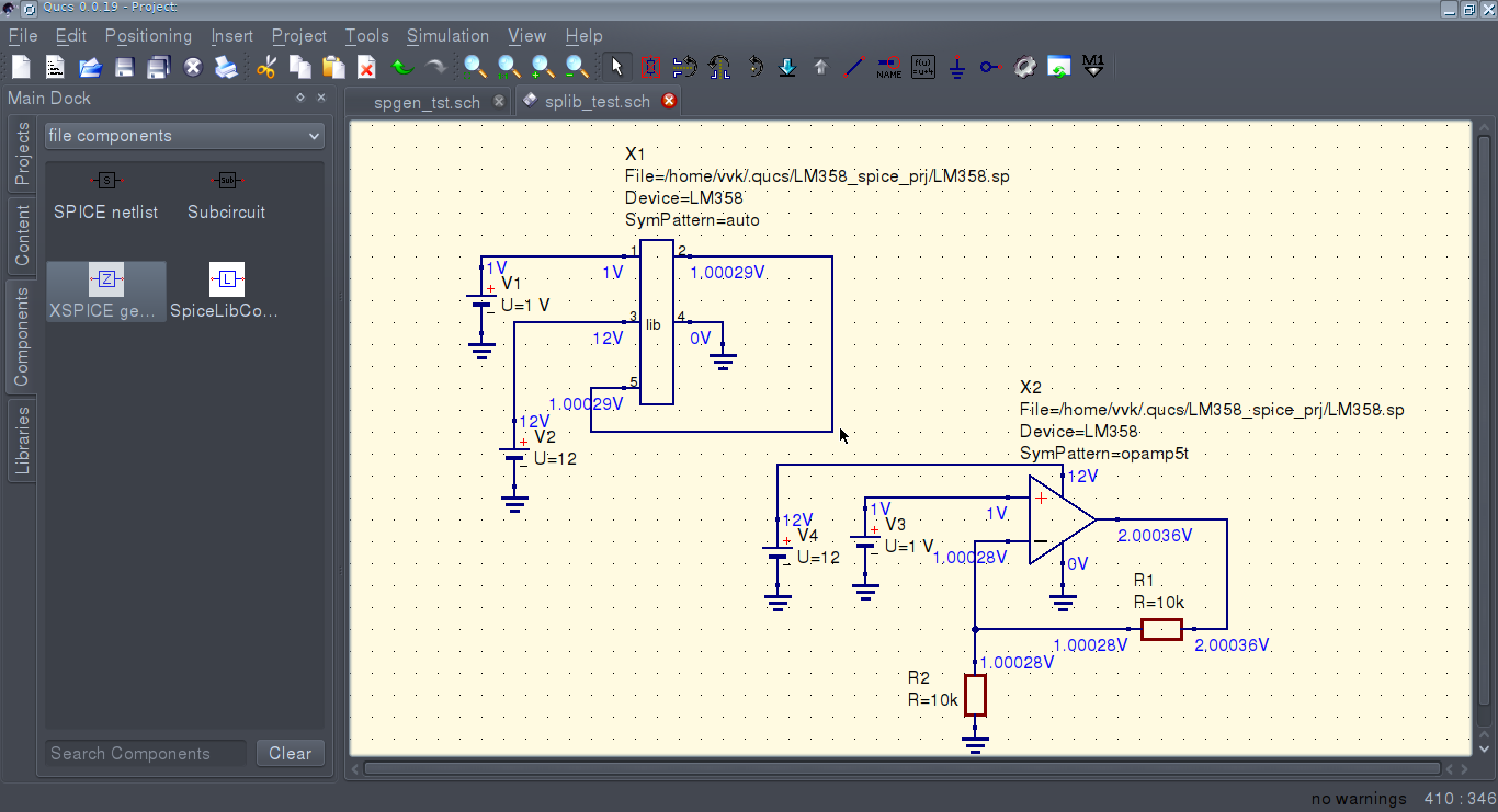
A special component “SPICE Library device” has been added, which allows using SPICE libraries without their modification and compatibility layers. You can use one of the available symbol patterns for the component. So far, only templates for OU with 3 or 5 outputs are available. It is enough to specify the path to the library, the name of the component, the symbol pattern and, if necessary, the parameters of the component. The diagrams illustrate how it is possible to connect an op amp in this way. It is planned to automate this process. In the future, the SPICE libraries will be displayed in the library manager along with the native Qucs libraries, and components from them will be available for insertion into the schema. It is also planned to add the editor of libraries and symbols by analogy with the PCAD Library Executive.
Conclusion
How exactly the QucsS project will continue to develop is unknown. Currently, Qucs and QucsS are quite different. I am considering various options. Perhaps Qucs and QucsS will merge this year. But it is possible and the selection of QucsS in an independent project with a different name already this year.
Source: https://habr.com/ru/post/302006/
All Articles