TV countdown timer on AVR microcontroller
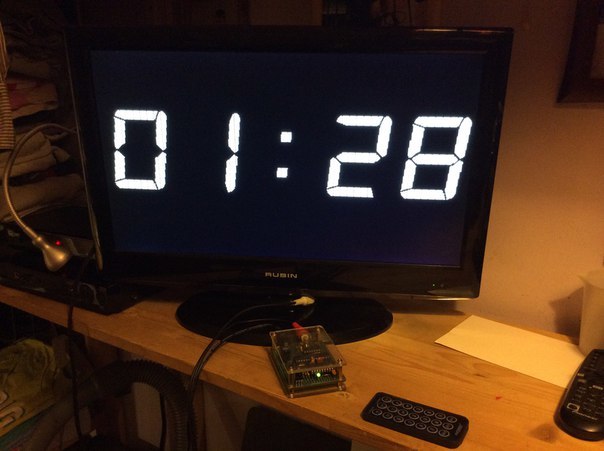
One day, a friend of mine asked me what I would do with a countdown timer so that I could show big numbers on the TV. It is clear that you can connect a laptop / iPad / Android and write an application, only a laptop is cumbersome, and writing a mobile application neither a friend nor I have ever done.
And then I remembered that I saw on the network projects of TV terminals on the AVR microcontroller. Immediately, an idea appeared in my head to combine small characters into large ones and we decided to try. It somehow happened that I had to do the main work.
Of course, I have little experience in developing devices on the MK, but it is always easier to get ready, so I started with an active search for a ready solution for outputting to a TV. The main criterion for the search was, first of all, simplicity, if possible, the use of C language without assembly inserts, high image quality.
')
Many projects were found, but it turned out that most of them do not meet the criteria. Subsequently, it became clear that the main thing is to understand the principle of the formation of a video signal, and then it will go further. But at this stage, the unconditional favorite was the project “Simple VGA / Video Adapter” by Maxim Ibragimov , he formed the basis of my crafts. However, in the process of work, only the structure remained of it, the implementation had to be redone almost completely.
An additional task, which I practically invented myself, was the task of starting time from the IR remote control.
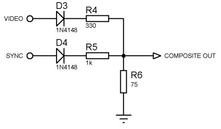
As the main controller, I decided to use ATMega168, running at 20 MHz. The hardware part of the video signal conditioner looks like this:
I started by throwing out everything that concerns VGA from the project, since I did not plan to do it. Along the way, I studied the video coding standards, the most accessible picture seemed to me from the Martin Hinner site :
 .
.For this picture did the synchronization signal generator.
At the heart of the generator - Timer1 in fastPWM mode. Additionally, a global variable has a clock counter. For each timer overflow interrupt, the sync pulse number is checked for a key value, a change in the duration of the next sync pulse and a period of the next sync pulse (full line / half line). If no changes are required, standard actions are made — the clock counter increases, other variables change.
#define
// 2. System definitions #define Timer_WholeLine F_CPU/15625 //One PAL line 64us #define Timer_HalfLine Timer_WholeLine/2 //Half PAL line = 32us #define Timer_ShortSync Timer_WholeLine/32 //2us #define Timer_LongSync Timer_ShortSync*15 //30us #define Timer_NormalSync Timer_WholeLine/16 //4us #define Timer_blank Timer_WholeLine/8 //8us //Global definitions for render PAL #define PAL_FPS 50 #define pal_first_visible_line1 40 #define pal_last_visible_line1 290 //pal_first_visible_line1+pal_row_count*pal_symbol_height #define horiz_shift_delay 15 Timer initialization (function fragment)
// Initialize Sync for PAL synccount = 1; VIDEO_DDR |= (1<<SYNC_PIN); OCR1B = Timer_LongSync; TCCR1A = (1<<COM1B1)|(1<<COM1B0)|(0<<WGM10)|(1<<WGM11); //Fast PWM,Set OC1B on Compare Match, // clear OC1B at BOTTOM (inverting mode) TCCR1B = (1<<WGM12)|(1<<WGM13)|(1<<CS10); //full speed;TOP = ICR1 ICR1 = Timer_HalfLine; // . TIMSK1 = (1<<OCIE1B); //enable interrupt from row_render=0; y_line_render=0; Clock signal generator
// volatile unsigned int synccount; // EMPTY_INTERRUPT (TIMER1_COMPB_vect); void MakeSync(void) { switch (synccount) { case 5://++++++++++++++++++++++++++++++++++++++++++++++++++++++++= Sync=Timer_ShortSync; synccount++; break; case 10://++++++++++++++++++++++++++++++++++++++++++++++++++++++++ ICR1 = Timer_WholeLine; Sync= Timer_NormalSync; synccount++; break; case 315://++++++++++++++++++++++++++++++++++++++++++++++++++++++++ ICR1 = Timer_HalfLine; Sync= Timer_ShortSync; synccount++; break; case 321://++++++++++++++++++++++++++++++++++++++++++++++++++++++++ Sync=Timer_LongSync; synccount=1; framecount++; linecount = 0; break; default://++++++++++++++++++++++++++++++++++++++++++++++++++++++++ synccount++; video_enable_flg = ((synccount>pal_first_visible_line1)&&(synccount<pal_last_visible_line1)); break; } } 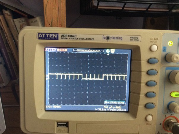
At the end of each line, the controller goes into sleep, interrupts the timer overflow, wakes up immediately after the MakeSync () function sets the timer settings for the next synchronization period, after which, if the number of the synchrometer enters the visible area, video output begins.
Video output is organized via SPI, operating at a maximum frequency equal to half the clock frequency.
#define
#define SPI_PORT PORTB #define SPI_DDR DDRB #define MOSI PORTB3 #define MISO PORTB4 #define SCK PORTB5 // #define VIDEO_PORT SPI_PORT #define VIDEO_DDR SPI_DDR #define VIDEO_PIN MOSI #define VIDEO_OFF DDRB=0b00100100; #define VIDEO_ON DDRB=0b00101100; SPI Initialization (snippet)
//Set SPI PORT DDR bits VIDEO_DDR |= (1<<MOSI)|(1<<SCK)|(0<<MISO); SPSR = 1 << SPI2X; SPCR = (1 << SPE) | (1 << MSTR); //SPI enable as master ,FREQ = fclk/2 The output process itself is carried out in each line by the function DrawString, which is passed as a pointer to an array of digits for output, a pointer to the font used and the number of characters to be output as parameters. Also, the output uses global variable numbers of the displayed line in each font and character numbers. Within each character, in a loop with the number of iterations equal to the width of this character in bytes, these bytes of the font are transferred to the SPDR register.
In addition, the hardware implementation of SPI in the AVR controller cannot transmit several data bytes in a row. After each byte, one bit is skipped, which causes gaps in the image.
Small explanation
Even a little bit wrong. The MOSI output remains at a high level after the transfer of a byte, and on this photo the video output is switched on via the 74S04 inverter, and the font bytes are inverted before being output, therefore the gaps are black. Without an inverter, white vertical stripes are obtained.
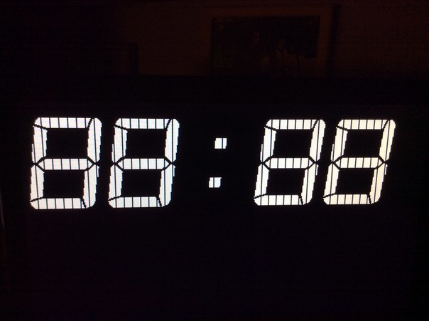
To defeat this drawback, we had to use the trick proposed in the TellyMate project, which consists in switching the video output pin to a high-impedance state when necessary, and thus repeating the last bit in the output byte. This part of the function is very time critical and the failure of the assembler has led to the need to
Line output function
inline void DrawString (unsigned char *str_buffer[], struct FONT_INFO *font, unsigned char str_symbols) { unsigned char symbol_width; unsigned char i; unsigned char * _ptr; unsigned char * _ptr1; y_line_render++; //Set pointer for render line (display buffer) _ptr = &str_buffer[row_render * str_symbols]; unsigned char j; register unsigned char _S; unsigned char _S1; //Cycle for render line i = str_symbols; while(i--) { symbol_width = font->width[(* _ptr)]; //Set pointer for render line (character generator) _ptr1 = &font->bitmap[font->offset[* _ptr]+y_line_render*symbol_width]; _S1 = 0; // _S = pgm_read_byte(_ptr1); // _ptr1++; j=symbol_width; // while (1) { if (_S1 & 0b1) { goto matr; } VIDEO_OFF; matr: NOP; SPDR = _S; VIDEO_ON; _S1 = _S; _S = pgm_read_byte(_ptr1++); NOP; NOP; if (!--j) break; } _ptr++; VIDEO_OFF; } } After the image was received, it became clear that there was no talk of receiving and parsing the IR parcels from the console, just not enough speed, so I left the reception of commands via the UART. IR reception will be done by another microcontroller.
Also added a second buffer that is needed to display the clock. Accordingly, there will be two fonts too. The structure of the font file consists of the actual character bitmaps, the font height constant, and the arrays of the offsets of each character and the width of each character.
There is also a structure describing the font for easier access from the program.
Font
// Character bitmaps for Digital-7 Mono 120pt const unsigned char PROGMEM Digital7_Bitmaps[] = { // @0 '0' (71 pixels wide) 0x00, 0x00, 0xFF, 0xFF, 0xFF, 0xFF, 0xFF, 0xF8, 0x80, // ############################################# # 0x00, 0x03, 0xFF, 0xFF, 0xFF, 0xFF, 0xFF, 0xF8, 0xE0, // ############################################### ### 0x00, 0x07, 0xFF, 0xFF, 0xFF, 0xFF, 0xFF, 0xF1, 0xF0, // ############################################### ##### 0x00, 0x0F, 0xFF, 0xFF, 0xFF, 0xFF, 0xFF, 0xF1, 0xF8, // ################################################ ###### ... ... } const unsigned char Digital7_Height = 105; const unsigned char Digital7_Width[] = { 9, /* 0 */ 9, /* 1 */ 9, /* 2 */ 9, /* 3 */ 9, /* 4 */ 9, /* 5 */ 9, /* 6 */ 9, /* 7 */ 9, /* 8 */ 9, /* 9 */ 3 /* : */ }; const unsigned int Digital7_Offset[] = { 0 , /* 0 */ 945, /* 1 */ 1890, /* 2 */ 2835, /* 3 */ 3780, /* 4 */ 4725, /* 5 */ 5670, /* 6 */ 6615, /* 7 */ 7560, /* 8 */ 8505, /* 9 */ 9450 /* : */ }; Fonts generated by the DotFactory program.
During the invisible part of the frame, the clock and timer move is made, as well as the reaction to the commands received via the UART.
UART reception
unsigned char clock_left; bool clock_set; volatile unsigned char MinTens, MinOnes; volatile unsigned char SecTens, SecOnes; static void pal_terminal_handle(void) { unsigned char received_symbol = 0; // Parser received symbols from UART while(UCSR0A & (1<<RXC0)) { received_symbol = UDR0; if (received_symbol=='#') { clock_left=5; clock_set = true; } if ((received_symbol>0x2F)&&(received_symbol<0x3A)) { if (clock_set) { time_array[5-clock_left] = received_symbol - 0x30; clock_left--; if (clock_left==3) { clock_left--; } if (clock_left==0) { time_array[6] = 0; time_array[7] = 0; clock_set = false; } } else { if ((pause==0)||_Stop) { MinTens = 0; } else { MinTens = MinOnes; } MinOnes = received_symbol - 0x30; SecTens = 0; SecOnes = 0; pause = 4; _Stop = false; str_array[0] = MinTens; str_array[1] = MinOnes; str_array[2] = 0x0A; str_array[3] = SecTens; str_array[4] = SecOnes; } //time_array[] = {1, 2, 10, 5, 5}; } } } Main () function;
volatile bool _Stop; struct FONT_INFO { unsigned char height; unsigned char * bitmap; unsigned int * offset; unsigned char * width; } Digital7, comdot; int main(void) { avr_init(); //fonts Digital7.bitmap = &Digital7_Bitmaps; Digital7.height = Digital7_Height; Digital7.offset = &Digital7_Offset; Digital7.width = &Digital7_Width; comdot.bitmap = &comdotshadow_Bitmaps; comdot.height = comdotshadow_Height; comdot.offset = &comdotshadow_Offset; comdot.width = &comdotshadow_Width; MinTens = 0; MinOnes = 0; SecTens = 0; SecOnes = 0; str_array[0] = MinTens; str_array[1] = MinOnes; str_array[2] = 0x0A; str_array[3] = SecTens; str_array[4] = SecOnes; unsigned char *semicolon = &time_array[2]; sei(); while (1) { sleep_mode(); MakeSync(); if (UCSR0A & (1<<RXC0)) { //Parse received symbol pal_terminal_handle(); //Can easealy add here RX polling buffer //to avoid display flickering continue; } //Check visible field if(video_enable_flg) { linecount++; //OK, visible //Main render routine #define firstline 36 #define secondline 200 //To make horizontal shift rendered image unsigned char k; for (k=horiz_shift_delay; k>0; k--) { NOP; } if ((linecount == firstline)||(linecount == secondline)) { row_render = 0; y_line_render = 0; } if ((linecount> firstline) && (linecount< firstline+(Digital7.height))) { DrawString(&str_array, &Digital7, 5); } if ((linecount> secondline) && (linecount< secondline+(comdot.height))) { DrawString(&time_array, &comdot, 5); } } else { //Not visible //Can do something else.. //You can add here your own handlers.. // VIDEO_OFF; if (framecount==PAL_FPS) { framecount=0; //========================================= if (*semicolon== 11) { *semicolon=10; } else { *semicolon=11; } if (++time_array[7] == 10) { framecount = 1;// time_array[7]=0; if (++time_array[6]==6) { framecount = 3; // time_array[6]=0; if (++time_array[4]==10) { time_array[4]=0; if (++time_array[3]==6) { time_array[3]=0; if ((++time_array[1]==4) && (time_array[0]==2)) { time_array[0]=0; time_array[1]=0; } if (time_array[1]== 9) { time_array[1]=0; time_array[0]++; } } } } } //========================================= if ((pause==0)&&(_Stop==false)) { if ((SecOnes--)==0) { SecOnes=9; if ((SecTens--) == 0) { SecTens = 5; if ((MinOnes--) == 0) { MinOnes = 9; if (MinTens == 0) { _Stop = true; } else { MinTens--; } } } } if (!_Stop) { str_array[0] = MinTens; str_array[1] = MinOnes; str_array[2] = 0x0A; str_array[3] = SecTens; str_array[4] = SecOnes; } } else { pause--; } } } } } As a controller that decodes the IR remote and sends commands via the UART, I took ATTiny45. Since it does not have a hardware UART, on the Internet, a very compact function of a software UART that works only on sending was found, as well as a simple function of reading commands from the console (without decoding).
All this was quickly compiled and compiled. Codes of buttons of the console are rigidly stitched in the code. Additionally made a flashing LED when receiving a command.
IR receiver and UART
/ *
* Tiny85_UART.c
*
* Created: 04/19/2016 21:22:52
* Author: Antonio
* /
#include <avr / io.h>
#include "dbg_putchar.h"
#include <avr / interrupt.h>
// # include <stdlib.h>
#include <stdbool.h>
// threshold value for comparing the length of pulses and pauses
static const char IrPulseThershold = 9; // 1024/8000 * 9 = 1.152 msec
// determines the timeout for receiving the parcel
// and limits the maximum length of the pulse and pause
static const uint8_t TimerReloadValue = 100;
static const uint8_t TimerClock = (1 << CS02) | (1 << CS00); // 8 MHz / 1024
volatile unsigned char blink = 0;
#define blink_delay 3;
volatile struct ir_t
{
// flag start receiving polylka
uint8_t rx_started;
// received code
uint32_t code,
// receive buffer
rx_buffer;
} ir;
static void ir_start_timer ()
{
TCNT0 = 0;
TCCR0B = TimerClock;
}
// when the timer overflows, we believe that the parcel is accepted
// copy the received code from the buffer
// reset the flags and stop the timer
ISR (TIMER0_OVF_vect)
{
ir.code = ir.rx_buffer;
ir.rx_buffer = 0;
ir.rx_started = 0;
if (ir.code == 0)
TCCR0B = 0;
TCNT0 = TimerReloadValue;
}
ISR (TIMER1_OVF_vect)
{
if (blink == 0)
{
OCR1B = 0;
}
else
{
OCR1B = 200;
blink--;
}
}
// external interrupt on the front and the decline
ISR (INT0_vect)
{
uint8_t delta;
if (ir.rx_started)
{
// if the pulse / pause duration is more than the threshold
// move the buffer unit one otherwise zero.
delta = TCNT0 - TimerReloadValue;
ir.rx_buffer << = 1;
if (delta> IrPulseThershold) ir.rx_buffer | = 1;
}
else {
ir.rx_started = 1;
ir_start_timer ();
}
TCNT0 = TimerReloadValue;
}
void dbg_puts (char * s)
{
while (* s) dbg_putchar (* s ++);
}
int main (void)
{
GIMSK | = _BV (INT0);
MCUCR | = (1 << ISC00) | (0 << ISC01);
TIMSK = (1 << TOIE0) | (1 << TOIE1);
ir_start_timer ();
dbg_tx_init ();
DDRB | = _BV (PB4);
TCCR1 | = (1 << CS13) | (1 << CS12) | (0 << CS11) | (0 << CS10);
GTCCR | = (1 << COM1B1) | (0 << COM1B0) | (1 << PWM1B);
OCR1C = 255;
OCR1B = 0;
blink = 0;
sei ();
// dbg_puts (& HelloWorld);
while (1)
{
// if ir.code is not zero, then we have adopted a new command
if (ir.code)
{
// convert the code to a string
//ultoa(ir.code, buf, 16);
// dbg_puts (buf); // and output to port
// =============================================== ==================
switch (ir.code)
{
case 0x2880822a: blink = blink_delay; dbg_putchar ('1'); break;
case 0x8280282a: blink = blink_delay; dbg_putchar ('2'); break;
case 0x8a0020aa: blink = blink_delay; dbg_putchar ('3'); break;
case 0x0a00a0aa: blink = blink_delay; dbg_putchar ('4'); break;
case 0x0280a82a: blink = blink_delay; dbg_putchar ('5'); break;
case 0x2a888022: blink = blink_delay; dbg_putchar ('6'); break;
case 0x0200a8aa: blink = blink_delay; dbg_putchar ('7'); break;
case 0x0a80a02a: blink = blink_delay; dbg_putchar ('8'); break;
case 0x22888822: blink = blink_delay; dbg_putchar ('9'); break;
case 0x20888a22: blink = blink_delay; dbg_putchar ('0'); break;
case 0x0008aaa2: blink = blink_delay; dbg_putchar ('O'); break;
case 0x280882a2: blink = blink_delay; dbg_putchar ('U'); break;
case 0x8880222a: blink = blink_delay; dbg_putchar ('D'); break;
case 0x0808a2a2: blink = blink_delay; dbg_putchar ('L'); break;
case 0xa0080aa2: blink = blink_delay; dbg_putchar ('R'); break;
case 0x20088aa2: blink = blink_delay; dbg_putchar ('*'); break;
case 0x220888a2: blink = blink_delay; dbg_putchar ('#'); break;
default: break;
}
ir.code = 0;
// =============================================== ===================
}
}
}
The final scheme was as follows:

The first version was assembled on a breadboard with the use of pieces of plexiglass as a case.

The power supply unit bought the simplest 12V 500mA at a local store.
Pultik ordered on ebay.
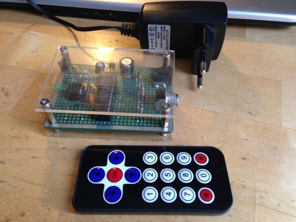
Here is the result:
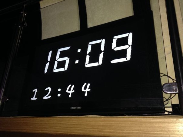
The timer is used to inform the speaker from the department of the allotted time.

The plans - to remake on stm32, fit into one controller, draw in the case more beautiful.
Thanks for attention.
Source: https://habr.com/ru/post/301598/
All Articles