Import a DXF drawing in a Java program, stepping on all the rakes of this “simple” format
AutoCAD and similar CAD systems have long become a standard in the field of design, and it is not surprising that the DWG / DXF file formats used in them became the same standard. So if you are developing some kind of solution for architects and designers, the ability to work with these formats (or at least one of them) is a must have feature of your product.

As part of my web service to simulate the movement of pedestrians, I had to attend to import master plans in these formats. I didn’t deal with CAD in the past, so I naively thought, “What else would you think - another format of drawings, lines and polygons, what could be complicated there?”. But in the process of work, it turned out that there may be enough complicated there, some nuances are quite similar to ancient crutches stretching from the depths of centuries, while many things are not properly documented in the specifications of the format itself (for example, working with blocks or with curves). Apparently they are considered obvious to any draftsman, but what to do if you are from another area, and you do not have such knowledge?
')
In general, under the cut - a list of rakes and decisions that could not google and had to get midnight vigils over the drawings.
Solvable problem
For my Java application, I needed to set up import of master plans of regions and convert it into an internal simplified GeoJSON view. In this case, I did not need complete information and all kinds of entities, only some of them that would be used in the simulation. So this material does not cover all features and Nontrivial DXF Technical Solutions. And why DXF, but not DWG? And about this below.
Format selection
So, what is primarily associated with the words "autocad" and "file format"? This is a DWG. The binary closed format, which was originally created by AutoDesk, and its specifications were not disclosed, but in due time it was successfully reversed by the Open Design Alliance.
And here comes the disappointment # 1: there are no actual free implementations of this format. At all.
There is a library to work with it from AutoDesk. There is a popular Teigha library, created by ODA. And ... everything. Both are paid, and well paid (talking about hundreds and thousands of dollars). Does not fit.
There are a number of attempts to implement the standard as a free open-source solution. For example jdwglib . But they are all dead for a long time, last updated 5-10 years ago. But progress does not stand still, new versions of auto-casts add new features to DWG, as a result, you can say goodbye to the dream of reading files of modern versions, as well as with the support and hope of fixing bugs.
An alternative is DXF. Somewhat less popular, but at the same time supported by all CAD systems, initially open and therefore, in theory, more common.
The search for libraries at first is also discouraging - specifically for Java there is not a single living project, the same picture everywhere: recent releases 5 years ago, abandoned repositories, latest news sadly gazing into eternity, full of unjustified optimism and promises. But by itself, the format, in contrast to DWG, is not so actively developed, so even with a fairly old library it is quite possible to open current drawings.
As a result, the Kabeja library was selected, the last release of which was in 2011. Using the bundled sample (DXF to SVG conversion), it was checked that all actual drawing files open correctly, after which I proceeded to import. One comment on the issue of parsing DXF from a certain CAD-guru on Stackoverflow, which, they say, “DXF looks simple, but in reality you will be tired of working with him.”
Layers
DXF drawing contains a set of layers (layer) and blocks (block). There are other entities there, but in order to rip out the coordinates of the geometry in the simplest case, they are not needed.
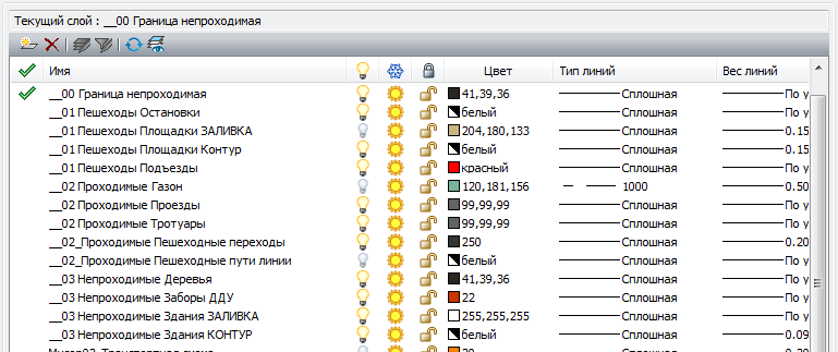
Everything is obvious with layers, they work the same way as in some Photoshop. Layers can be turned on and off and you can set default graphics settings for a layer (that is, for example, all lines by default on this layer will have such and such thickness). Since my task was only to squeeze the coordinates, I did not deal with mapping issues.
Okay, everything seems simple: we run through the list of layers, for each layer - according to the list of objects, we transform the coordinates. But already here I stepped on the first rake: the set of layers that you see in CAD and which is in the file is not the same thing . I broke my head, why I suddenly lost pieces of the road. They are in NanoCAD, not in my export. I got into the debugger - they are not in the returned Kabeja structures either. But if you export the file entirely with their sample - they are. In general, it turned out that one layer from the editor in the file can be represented by several layers, with names like "layerName", "layerName @ 1". Why it is done and where it comes from - the devil knows it, but the fact is that searching for an exact match of the name of the layer (which even the structure of the library code storing the layers in the Map with the name key hints at) does not work.
Blocks
Blocks are templates that once drawn can be repeatedly inserted. In this case, a change in the base unit will change all its inserts. Conveniently. Even cooler is that the block can contain objects from several layers. In this case, the insert also belongs to some layer. In this case, the block may contain inserts of other blocks. That is, you can make blocks "section of the house", then make a block of them "house", which is then inserted several times on the card. In this case, the final object will have several layers (separate fill, separate contours, separate special marks), as well as the original blocks. All this is very cool from the user's point of view, but adds work to the programmer.
Moreover, a block can be inserted not just once, but repeatedly as a rectangular matrix. For this, the insertion object has parameters with the number of rows, columns and the distance between them.
As a result, the insertion processing code looks something like this:
It is also important to know that the blocks and layers in the file are not ordered . That is, alternately processing blocks, you can stumble into it on an insert from another block that has not yet been processed. To be honest, I don’t know if it is possible to manage to make a cycle and what will happen in that case.
Lines
Let me remind you that my task is to convert DXF to GeoJSON, which of all types of geometry recognizes only a broken line and a polygon, no arcs and curves.
DXF supports a bunch of different line options:
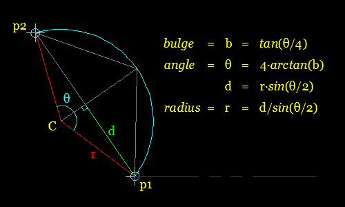
It would seem simple, but no. Even the seemingly simple Polyline type can be used to display second-order curves (and not just broken lines). To do this, the bulge parameter can be set at the top. If it is specified, then two vertices are connected not by a straight line, but by an arc of a circle passing through these vertices and the center of which can be expressed through them and this parameter.
Here is the code to determine the center of the circle:
I fought over these arcs for a long time, but in the end I spat and turned them off, connecting the vertices directly. Since in the general plans such arcs are usually used for rounding off at the corners of intersections, I could score on them completely - the difference in terms of simulation is small.
Fill / hatch
This is what my simulator works directly with. Buildings, roads and generators, for the time being, I demand to specify with fillings (otherwise it is not clear where the interior is in the jumble of individual lines, and where is the exterior).
And here, too, there are nuances:

In general, from DXF for filling, we get a bunch of borders that have the flag “external or internal”, and then we have to somehow figure out how they are made and how to scatter them along GeoJSON polyvons, which can have only one external border and not have nesting.
I went in several ways, but for each algorithm I rather quickly received a drawing on which this algorithm did not work. For example, this one is here: a street and driveway scheme for a residential area of Chita, in which they are all set with literally a couple of HATCH objects with a very complex structure, in which for some reason all borders were marked as external (I sense some kind of bug in Kabeja, as DXF defines at once two similar flags External and Outer, but in the library there is only one):
As a result, the only working algorithm looks like this:
For the third point (and indeed for working with the geometry already inside the simulation algorithm itself), I used the JTS library - Java Topology Suite. It contains quite a lot of all sorts of necessary primitives and operations on working with geometry, starting from operations such as building a buffer and ending with data structures such as a quadtree.
Victory?
After a lot of torment and having propped everything up with crutches, I nevertheless managed to create support for the DXF subset I needed and upload the drawings directly to my simulator, in order to use them to determine the designers' shoals. Since I had to extract most of the above information with combat and sitting up to two nights over NanoCAD (not advertising, but this is the only easily accessible free and high-quality DXF editor I found, the same LibreCAD did not master the right to open the first drawing that I did I gave it to him), I decided to share it with the habrasoobschestvom - suddenly my experience will save someone time.
Well, yes, here is how the prediction of my algorithm looks for the region from the screenshot above:
Obvious conclusions - do not make tracks at right angles, but do not and try to make some strange rounding where there is no need. We'll see in a few years if my prediction when the area is built is justified.
Thanks for the plans of the districts thanks to the Integrated Architectural and Construction Design Workshop
As part of my web service to simulate the movement of pedestrians, I had to attend to import master plans in these formats. I didn’t deal with CAD in the past, so I naively thought, “What else would you think - another format of drawings, lines and polygons, what could be complicated there?”. But in the process of work, it turned out that there may be enough complicated there, some nuances are quite similar to ancient crutches stretching from the depths of centuries, while many things are not properly documented in the specifications of the format itself (for example, working with blocks or with curves). Apparently they are considered obvious to any draftsman, but what to do if you are from another area, and you do not have such knowledge?
')
In general, under the cut - a list of rakes and decisions that could not google and had to get midnight vigils over the drawings.
Solvable problem
For my Java application, I needed to set up import of master plans of regions and convert it into an internal simplified GeoJSON view. In this case, I did not need complete information and all kinds of entities, only some of them that would be used in the simulation. So this material does not cover all features and Nontrivial DXF Technical Solutions. And why DXF, but not DWG? And about this below.
Format selection
So, what is primarily associated with the words "autocad" and "file format"? This is a DWG. The binary closed format, which was originally created by AutoDesk, and its specifications were not disclosed, but in due time it was successfully reversed by the Open Design Alliance.
And here comes the disappointment # 1: there are no actual free implementations of this format. At all.
There is a library to work with it from AutoDesk. There is a popular Teigha library, created by ODA. And ... everything. Both are paid, and well paid (talking about hundreds and thousands of dollars). Does not fit.
There are a number of attempts to implement the standard as a free open-source solution. For example jdwglib . But they are all dead for a long time, last updated 5-10 years ago. But progress does not stand still, new versions of auto-casts add new features to DWG, as a result, you can say goodbye to the dream of reading files of modern versions, as well as with the support and hope of fixing bugs.
An alternative is DXF. Somewhat less popular, but at the same time supported by all CAD systems, initially open and therefore, in theory, more common.
The search for libraries at first is also discouraging - specifically for Java there is not a single living project, the same picture everywhere: recent releases 5 years ago, abandoned repositories, latest news sadly gazing into eternity, full of unjustified optimism and promises. But by itself, the format, in contrast to DWG, is not so actively developed, so even with a fairly old library it is quite possible to open current drawings.
As a result, the Kabeja library was selected, the last release of which was in 2011. Using the bundled sample (DXF to SVG conversion), it was checked that all actual drawing files open correctly, after which I proceeded to import. One comment on the issue of parsing DXF from a certain CAD-guru on Stackoverflow, which, they say, “DXF looks simple, but in reality you will be tired of working with him.”
Layers
DXF drawing contains a set of layers (layer) and blocks (block). There are other entities there, but in order to rip out the coordinates of the geometry in the simplest case, they are not needed.
Everything is obvious with layers, they work the same way as in some Photoshop. Layers can be turned on and off and you can set default graphics settings for a layer (that is, for example, all lines by default on this layer will have such and such thickness). Since my task was only to squeeze the coordinates, I did not deal with mapping issues.
Okay, everything seems simple: we run through the list of layers, for each layer - according to the list of objects, we transform the coordinates. But already here I stepped on the first rake: the set of layers that you see in CAD and which is in the file is not the same thing . I broke my head, why I suddenly lost pieces of the road. They are in NanoCAD, not in my export. I got into the debugger - they are not in the returned Kabeja structures either. But if you export the file entirely with their sample - they are. In general, it turned out that one layer from the editor in the file can be represented by several layers, with names like "layerName", "layerName @ 1". Why it is done and where it comes from - the devil knows it, but the fact is that searching for an exact match of the name of the layer (which even the structure of the library code storing the layers in the Map with the name key hints at) does not work.
Blocks
Blocks are templates that once drawn can be repeatedly inserted. In this case, a change in the base unit will change all its inserts. Conveniently. Even cooler is that the block can contain objects from several layers. In this case, the insert also belongs to some layer. In this case, the block may contain inserts of other blocks. That is, you can make blocks "section of the house", then make a block of them "house", which is then inserted several times on the card. In this case, the final object will have several layers (separate fill, separate contours, separate special marks), as well as the original blocks. All this is very cool from the user's point of view, but adds work to the programmer.
Moreover, a block can be inserted not just once, but repeatedly as a rectangular matrix. For this, the insertion object has parameters with the number of rows, columns and the distance between them.
As a result, the insertion processing code looks something like this:
for (int row = 0; row < insert.getRows(); ++row) { for (int col = 0; col < insert.getColumns(); ++col) { // , . AffineTransform transform = new AffineTransform(); transform.translate( insert.getPoint().getX() - (insert.getColumns() - col) * insert.getColumnSpacing() , insert.getPoint().getY() - (insert.getRows() - row) * insert.getRowSpacing()); transform.rotate(Math.toRadians(insert.getRotate())); transform.scale(insert.getScaleX(), insert.getScaleY()); // Feature , GeoJSON for (Feature f : block.features) { // , . Feature inserted = cloneFeatureWithTransform(f, transform); features.add(inserted); } } } return block.features.size(); It is also important to know that the blocks and layers in the file are not ordered . That is, alternately processing blocks, you can stumble into it on an insert from another block that has not yet been processed. To be honest, I don’t know if it is possible to manage to make a cycle and what will happen in that case.
Lines
Let me remind you that my task is to convert DXF to GeoJSON, which of all types of geometry recognizes only a broken line and a polygon, no arcs and curves.
DXF supports a bunch of different line options:
- Already 2 types of broken lines - Polyline and LWPolyline. In my case, simple 2D drawings, there is no difference between them.
- Arcs, and as many as two types - elliptical and circular. Fortunately, the Kabeja classes already have ready-made methods for obtaining the coordinates of points on them, so it’s easy to transform an arc into a polyline with the necessary precision.
- Splines - again Kabeja is able to convert them into Polyline
- Just linear segments
It would seem simple, but no. Even the seemingly simple Polyline type can be used to display second-order curves (and not just broken lines). To do this, the bulge parameter can be set at the top. If it is specified, then two vertices are connected not by a straight line, but by an arc of a circle passing through these vertices and the center of which can be expressed through them and this parameter.
Here is the code to determine the center of the circle:
private Point getCenterByVerticesAndBulge(DXFVertex a, DXFVertex b, double bulge) { double norm = Math.sqrt(Math.pow(b.getX() - a.getX(), 2) + Math.pow(b.getY() - a.getY(), 2)); double s = norm / 2; double d = s * (1 - bulge * bulge) / (bulge * bulge); // "direction" double u = (b.getX() - a.getX()) / norm; double v = (b.getY() - a.getY()) / norm; //"center" double c1 = Math.signum(bulge) * -v * d + (a.getX() + b.getX()) / 2; double c2 = Math.signum(bulge) * u * d + (a.getY() + b.getY()) / 2; return new Point(c1, c2, 0); } I fought over these arcs for a long time, but in the end I spat and turned them off, connecting the vertices directly. Since in the general plans such arcs are usually used for rounding off at the corners of intersections, I could score on them completely - the difference in terms of simulation is small.
Fill / hatch
This is what my simulator works directly with. Buildings, roads and generators, for the time being, I demand to specify with fillings (otherwise it is not clear where the interior is in the jumble of individual lines, and where is the exterior).
And here, too, there are nuances:
- The border of a fill can be any combination of line objects. Part of the border can be broken, then a few arcs, then just a bunch of segments of different lines
- One fill object can have an arbitrary number of non-intersecting regions (which is uncharacteristic for many other formats where the polygon has only one outer boundary), each of which can have an arbitrary number of holes
- Fills can be repeatedly nested: that is, there is a hole inside the fill, in which there is another fill, in which there is again a hole, and all this in DXF is defined by one HATCH object with several borders.
- There are even more exotic variants of the relationship of pouring and its borders (see picture), but I still don’t thank God for them
In general, from DXF for filling, we get a bunch of borders that have the flag “external or internal”, and then we have to somehow figure out how they are made and how to scatter them along GeoJSON polyvons, which can have only one external border and not have nesting.
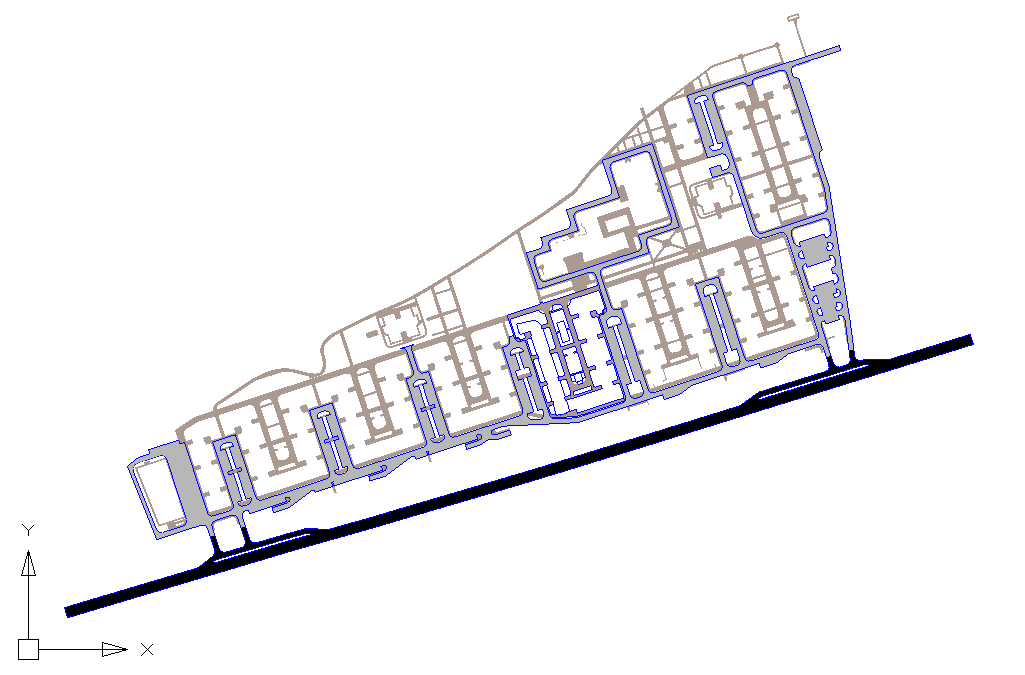
I went in several ways, but for each algorithm I rather quickly received a drawing on which this algorithm did not work. For example, this one is here: a street and driveway scheme for a residential area of Chita, in which they are all set with literally a couple of HATCH objects with a very complex structure, in which for some reason all borders were marked as external (I sense some kind of bug in Kabeja, as DXF defines at once two similar flags External and Outer, but in the library there is only one):
As a result, the only working algorithm looks like this:
- Create a polygon for each outer boundary.
- Subtract all other boundaries from it, whether they are marked by external or internal
- Correct possible problems (the polygon turned out to be empty, the holes go beyond the boundaries of the external contour, the polygon broke into unbound areas, etc.)
For the third point (and indeed for working with the geometry already inside the simulation algorithm itself), I used the JTS library - Java Topology Suite. It contains quite a lot of all sorts of necessary primitives and operations on working with geometry, starting from operations such as building a buffer and ending with data structures such as a quadtree.
Victory?
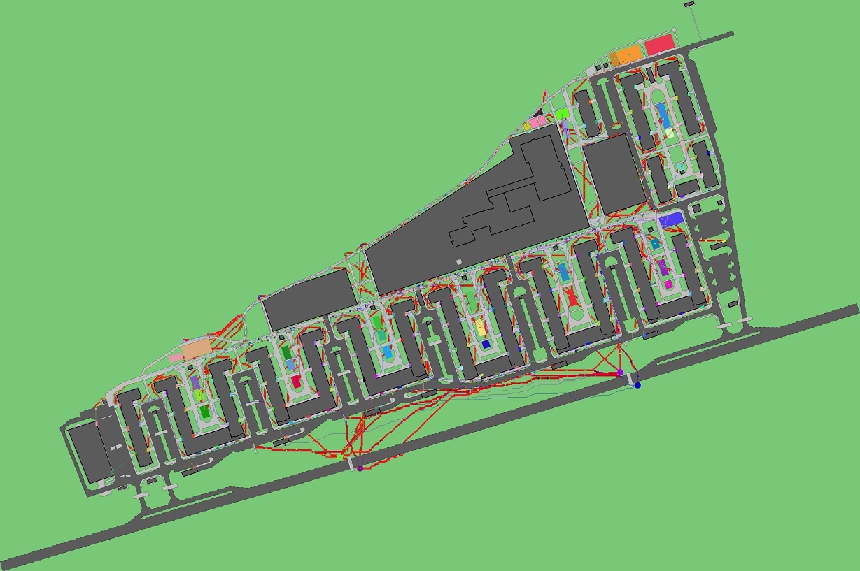
After a lot of torment and having propped everything up with crutches, I nevertheless managed to create support for the DXF subset I needed and upload the drawings directly to my simulator, in order to use them to determine the designers' shoals. Since I had to extract most of the above information with combat and sitting up to two nights over NanoCAD (not advertising, but this is the only easily accessible free and high-quality DXF editor I found, the same LibreCAD did not master the right to open the first drawing that I did I gave it to him), I decided to share it with the habrasoobschestvom - suddenly my experience will save someone time.
Well, yes, here is how the prediction of my algorithm looks for the region from the screenshot above:
Obvious conclusions - do not make tracks at right angles, but do not and try to make some strange rounding where there is no need. We'll see in a few years if my prediction when the area is built is justified.
Thanks for the plans of the districts thanks to the Integrated Architectural and Construction Design Workshop
Source: https://habr.com/ru/post/301484/
All Articles