Preparing mine infrastructure for the implementation of the RealTrac local positioning and voice communication system
Working in the RTL-Service company, recently I had to participate in mine surveys more than once, both coal and metal, in which some of our partners had previously introduced the RealTrac local positioning and voice communication system and it worked wrong or unstable. And each time it turned out that the reason for this work of the system is not the deficiencies of the equipment or software developed by our company, but errors and miscalculations in creating the infrastructure for the RealTrac system. By infrastructure I first of all understand 3 main components:
Issues of ensuring the correct infrastructure are particularly acute if our system is used mainly in the mine as a voice communication system, since the volume of transmitted traffic within the system in this case is much larger than when using only the local positioning functionality.
')
In this article I will try to formulate an algorithm for preparing the mine’s infrastructure for the deployment of our system, which can be used not only for local positioning systems, but also for other wireless solutions.
And you need to start with the correct placement of stationary equipment inside the mine. The system of local positioning in the mines is one-dimensional, since the tunnels, drifts, trunks, tunnels and other parts of the mines are one-dimensional objects from the point of view of the mine’s plan-scheme displayed on the computer screen. Accordingly, all access points providing coverage of the local positioning system and voice communications network are mounted inside the shaft in the form of chains. These chains consist of two types of access points:
When designing the arrangement of access points should be guided by the following principles:
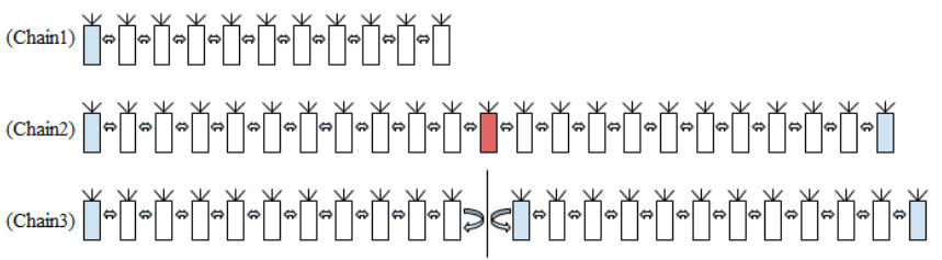
Figure 2 Examples of RTD chains
In view of the above, an indispensable tool when planning the placement of access points inside the mine is the RealTrac Local Positioning and Voice Communication Analyzer. This is a wearable device, developed by our company specifically for measuring over the radio channel various parameters of the system, including such as RSSI, the distance to all those in the area of audibility of the Device Analyzer and many others.
Using the Analyzer, when setting up access points in the mine, it will be necessary to measure RSSI at their installation sites and ensure that the values of this measurement to neighboring devices are at -70, -75 dBm, but the distance to the nearest neighbors should not exceed 200 m ( distance to neighbors can also be measured using the Analyzer). It is also recommended to closely monitor the number of neighboring RTDs recorded by the Analyzer - there should not be more than 4 of them (while being directly at the installation site of the device).
After the arrangement of access points has been planned, care should be taken to ensure their power supply.
The DC-DC boards at the access points use the PSR-7805LF stabilizer manufactured by PEAK ELECTRONICS, which requires a voltage of at least 6.5V, also contains intrinsically safe circuit components (3 diodes in series and a fuse) on which there is a voltage drop of about 1B. Thus, for stable operation of devices, it is required that the device supply voltage does not fall below 8V. The average consumption of a device is about 0.5W, but due to the fact that current consumption is pulsed, short-term voltage drops are possible. Since usually in the mine from one mine power source (SHIP) a whole chain of devices is powered by one cable at once, we recommend that the voltage value at the input of the outermost TD in the chain fed by one cable should not be lower than 10-10.5 V. can be achieved in the following ways:
Another important issue of providing infrastructure for the local positioning system and voice communication RealTrac, especially with the active use of voice communication functionality, is the provision of network infrastructure. The network infrastructure refers to the data transfer channels between the STD and the RealTrac server. All APs for connecting wired communication channels have one (two in some versions) 10 / 100BaseTX ports. For stable and trouble-free operation of the system, the following simple rules must be followed:
I am sure that if we properly prepare the infrastructure for the implementation of the RealTrac local positioning and voice communication system, taking into account the recommendations outlined in this article, then after its implementation, there will be no problems with the stability and correctness of our system. Experience shows that out of 10 incidents sent by our users to the technical support service, 7-8 is connected with infrastructure deficiencies.
Author: Oleg Chumakov
- Placement of stationary equipment (access points) inside the mine.
- Provide power to access points.
- Providing network infrastructure.
Issues of ensuring the correct infrastructure are particularly acute if our system is used mainly in the mine as a voice communication system, since the volume of transmitted traffic within the system in this case is much larger than when using only the local positioning functionality.
')
In this article I will try to formulate an algorithm for preparing the mine’s infrastructure for the deployment of our system, which can be used not only for local positioning systems, but also for other wireless solutions.
And you need to start with the correct placement of stationary equipment inside the mine. The system of local positioning in the mines is one-dimensional, since the tunnels, drifts, trunks, tunnels and other parts of the mines are one-dimensional objects from the point of view of the mine’s plan-scheme displayed on the computer screen. Accordingly, all access points providing coverage of the local positioning system and voice communications network are mounted inside the shaft in the form of chains. These chains consist of two types of access points:
- Access points - gateways (hereinafter referred to as SHDD). They interact with the mobile devices of the system (position labels, digital radios, etc.) and other access points via radio, and with the RealTrac server via the wired Ethernet interface.
- Access points - repeaters (hereinafter referred to as RTD). They interact with mobile devices and other access points via radio, they do not have wired connections. Data to the RealTrac server from such access points is transmitted through the DAC.
When designing the arrangement of access points should be guided by the following principles:
- Design must begin with the nodal points located at intersections and at the beginning of the tunnel (see Figure 1 - the nodal point is marked in red);

Figure 1 Example of the arrangement of access points inside the mine - The maximum number of neighbors of a nodal point at an X-shaped intersection is no more than 4 devices, while the RSSI (received signal level) readings to the nearest neighbors should be about 75 dBm. It should be noted that reducing this parameter by 6 dBm entails a two-fold deterioration of the coverage area.
- It is important that the devices that follow adjacent points be outside the audible point of the anchor point (see Figure 1 - the points are marked in gray).
- The maximum chain of devices should not exceed 10 devices (no more than 9 RTDs per 1 STD). Chain Chain1 in Figure 2 satisfies the requirements of the maximum number of devices.
- Chains of the form (1 x SHDD) + (10 x RTD) + (1 x SHDD) + (10 x RTD) + (1 x SHDD) should be avoided, because on the STD located in the middle of the chain, the entire load of 20 x RTD . Chain2 chain does not meet the requirements of the maximum number of devices, since the central DIA, marked in red, is under load from 20 RTDs (10 on the left and 10 on the right). Chain3 chain differs from Chain2 in that it has a radio-barrier septum. The chain satisfies the requirements of the maximum number of devices, since there are 10 RTDs on the first left-hand side of the STD, and the next RTD does not interact with the devices of the left-hand side. Thus, Chain3 chain is two chains (left and right) that do not have any radio interaction with each other.
Figure 2 Examples of RTD chains
In view of the above, an indispensable tool when planning the placement of access points inside the mine is the RealTrac Local Positioning and Voice Communication Analyzer. This is a wearable device, developed by our company specifically for measuring over the radio channel various parameters of the system, including such as RSSI, the distance to all those in the area of audibility of the Device Analyzer and many others.
Using the Analyzer, when setting up access points in the mine, it will be necessary to measure RSSI at their installation sites and ensure that the values of this measurement to neighboring devices are at -70, -75 dBm, but the distance to the nearest neighbors should not exceed 200 m ( distance to neighbors can also be measured using the Analyzer). It is also recommended to closely monitor the number of neighboring RTDs recorded by the Analyzer - there should not be more than 4 of them (while being directly at the installation site of the device).
After the arrangement of access points has been planned, care should be taken to ensure their power supply.
The DC-DC boards at the access points use the PSR-7805LF stabilizer manufactured by PEAK ELECTRONICS, which requires a voltage of at least 6.5V, also contains intrinsically safe circuit components (3 diodes in series and a fuse) on which there is a voltage drop of about 1B. Thus, for stable operation of devices, it is required that the device supply voltage does not fall below 8V. The average consumption of a device is about 0.5W, but due to the fact that current consumption is pulsed, short-term voltage drops are possible. Since usually in the mine from one mine power source (SHIP) a whole chain of devices is powered by one cable at once, we recommend that the voltage value at the input of the outermost TD in the chain fed by one cable should not be lower than 10-10.5 V. can be achieved in the following ways:
- Increasing the input supply voltage for the chain (the allowable limit in terms of device performance is 24V);
- Increased power cable cross section;
- Reducing the number of access points on a single power cable.
Another important issue of providing infrastructure for the local positioning system and voice communication RealTrac, especially with the active use of voice communication functionality, is the provision of network infrastructure. The network infrastructure refers to the data transfer channels between the STD and the RealTrac server. All APs for connecting wired communication channels have one (two in some versions) 10 / 100BaseTX ports. For stable and trouble-free operation of the system, the following simple rules must be followed:
- To ensure the bandwidth of the communication channel at the “STD - RealTrac Server” sites of at least 1 Mb / s per each STD;
- Eliminate the delay of the communication channel on the sites “SHDD - RealTrac Server” for more than 40 ms;
- Minimize the number of RTDs in chains of the form “(one) STDs - (many) RTDs”, according to the recommendations given above.
- If possible, minimize or eliminate the use of the network infrastructure allocated to the RealTrac system by other automated systems.
I am sure that if we properly prepare the infrastructure for the implementation of the RealTrac local positioning and voice communication system, taking into account the recommendations outlined in this article, then after its implementation, there will be no problems with the stability and correctness of our system. Experience shows that out of 10 incidents sent by our users to the technical support service, 7-8 is connected with infrastructure deficiencies.
Author: Oleg Chumakov
Source: https://habr.com/ru/post/301224/
All Articles