Benefits of Juniper Stacking
Part 1. Virtual chassis technology
One of the main advantages of Juniper solutions over its competitors is their stacking capabilities. There are quite a few options, starting from the base Virtual Chassis and ending with a variety of data center technologies.
Part 1. Virtual Chassis
')
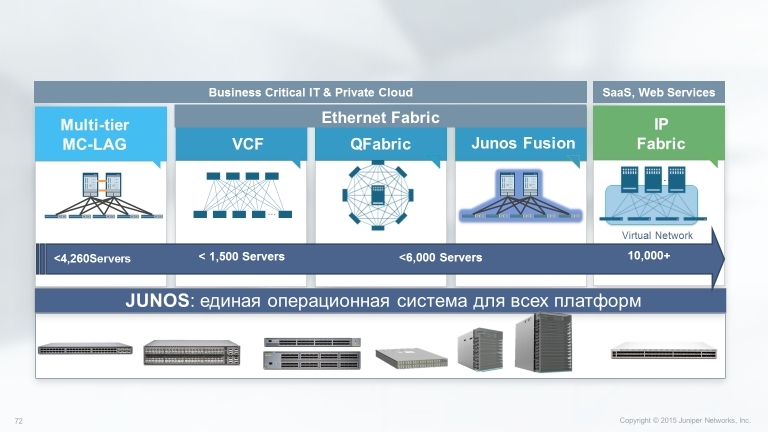
Consider the capabilities and features of the Virtual Chassis base technology, which allows you to combine up to 10 devices (depending on the model) of the EX series and QFX series into one logical device, as well as how to configure and monitor it.
To begin with, which models support the technology of Virtual Chassis:
• EX2200 Ethernet Switch up to 4 devices
• EX3300 Ethernet Switch up to 10 devices
• EX4200 Ethernet Switch up to 10 devices
• EX4300 Ethernet Switch up to 10 devices
• EX4550 Ethernet Switch up to 10 devices
• EX4600 Ethernet Switch up to 10 devices
• QFX5100 Switch up to 10 devices.
These are the models that at the time of this writing are produced and available for order, and, accordingly, can be used in the virtual chassis.
Virtual Chassis technologies combine the scalability and compact form factor of freestanding switches with high availability, bandwidth and port density of traditional chassis. Virtual Chassis allows you to provide cost-effective deployment of switches and network availability in places where the cost of installing chassis devices may be too high, or where it is physically impossible to install chassis switches.
Due to the fact that several devices are managed as a single unit, Virtual Chassis allows you to use the same redundancy capabilities as the use of several Routing Engine (RE) in chassis switches, including graceful Routing Engine switchover (GRES) technology.
To connect to a virtual chassis, specialized interfaces can be used that are on the EX4500, EX4550, and EX4200 devices, as well as copper and optical ports. Ports that are used to connect to a virtual chassis are called Virtual Chassis Ports (VCP). For example, in an EX2200-24T-4G 24 10/100 / 1000Base-T and 4 SFP switch, you can use either SFP or copper ports to connect to a virtual chassis. This allows you to spread the members of a single virtual chassis over a distance of 80 km.
Mixed Virtual Chassis makes it possible to use switches of different series and even different lines within one virtual chassis, as shown in the figure below.
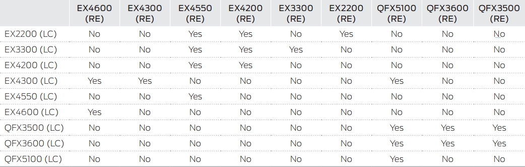
Options for stacking switches in Mixed Virtual Chassis
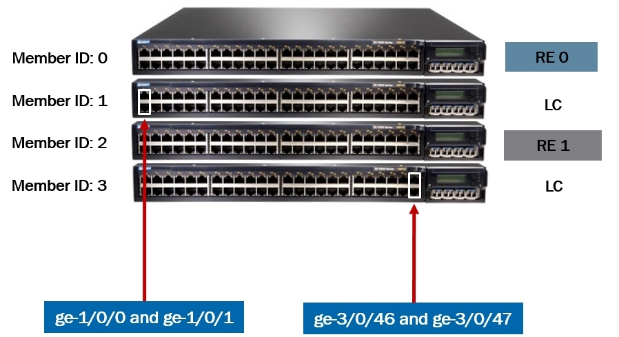
In the virtual chassis there is a separation by roles: two switches get the role RE0 and RE1, and the rest are used as line cards.
RE0 performs the role of a master whose task is to manage the remaining members of the virtual chassis, and it is he who is responsible for creating the routing tables and distributing them across the line cards. It also stores configuration files. RE1 - backup, in case of RE0 failure.
Consider the distribution of switch roles in a virtual chassis using the example below.
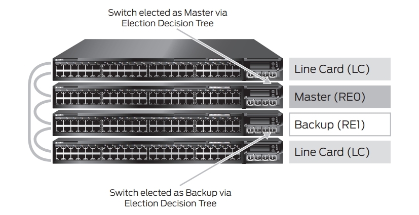
Criteria for choosing a master:
- The switch with the highest priority. The priority can be from 1 to 255, by default it is 128 on all switches;
- A switch that was a master before rebooting;
- Switch with the highest uptime (the difference should be more than 1 min) ;.
- Switch with the lowest MAC address.
Each member of the virtual chassis receives its ID from 0 to 9. You can manually configure this ID from the wizard (whose ID is 0) (after rebooting, the number is saved and can serve as a slot number in the interface definition).
Due to the fact that the ID is assigned to the switch, the following situation may arise: when one switch fails and you change it, the new member receives not the number of the failed switch, but the next free or not connected to the virtual chassis, if all ID is already taken.
Therefore, in order to replace a failed switchboard with a new one, you first need to remove its ID from the wizard as follows:
{master: 0}
user @ Switch-1> request virtual-chassis recycle member-id <member-id>
Or you can do this with the command ID:
user @ host> request virtual-chassis renumber member-id <current-member-id> new-member-id <new-member-id>
Single management interface and single console
Within the virtual chassis, all management interfaces are merged into one, with a single IP address:
{master: 0} [edit]
user @ switch # show interfaces vme
unit 0 {
family inet {
address 10.210.14.148/27;
}
}
{master: 0} [edit]
user @ Switch-1 # run show interfaces terse vme
Interface Admin Link Proto Local Remote
vme up up
vme.0 up up inet 10.210.14.148/27
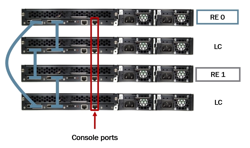
The same thing happens with the console port, no matter what you connect to, you will be taken to RE0.
Software compatibility
All members of the virtual chassis must be with the same version of the software. When we add a new switch to the virtual chassis, the wizard checks its version of the software; if the software is different, the new switch will receive an ID, but will not become an active member of the virtual chassis. To do this, you need to update the software on the new switch with the command:
request system software add member <member-id> reboot
This command downloads the image from the master switch through the VCPs of the new switch, and then reboots it, and the new switch may not be connected directly to the main switch.
Automatic software update
By configuring the automatic software update, when each new switch is connected to a version other than the wizard, its software will be automatically updated. set virtual-chassis auto-sw-update package-name <package-name>
Nonstop Software Upgrade
The Nonstop software upgrade (NSSU) technology allows you to upgrade software on all members of a virtual chassis with minimal loss. For this technology to work correctly, you need to:
- All members of the virtual chassis were connected to the “ring” topology;
- Master and backup were adjacent;
- Line cards have been configured in preconfiguration mode;
- On all members of the virtual chassis should be one version of the software;
- NSR and GRES should be included; Optionally, you can activate the NSB command request system snapshot.
NSSU process:
- Download the image of the software. If you use a mixed virtual chassis, then download both images.
- Copy it to RE0, recommended in the / var / tmp folder,
- From the command line RE0, launch NSSU with the command:
request system software nonstop-upgrade /var/tmp/package-name.tgz
or for mixed virtual chassis
request system software nonstop-upgrade set [/var/tmp/package-name.tgz /var/tmp/package-name.tgz]
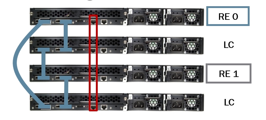
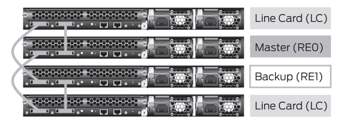
Recommended Master Switch and Backup Switch Location
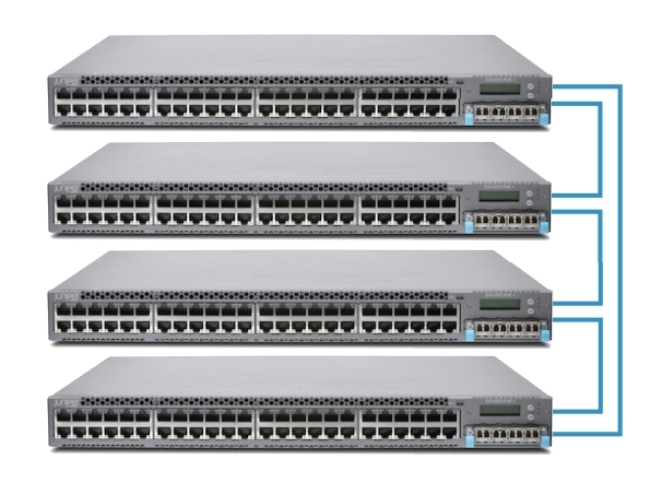
When building a virtual chassis, the following connection schemes are recommended:
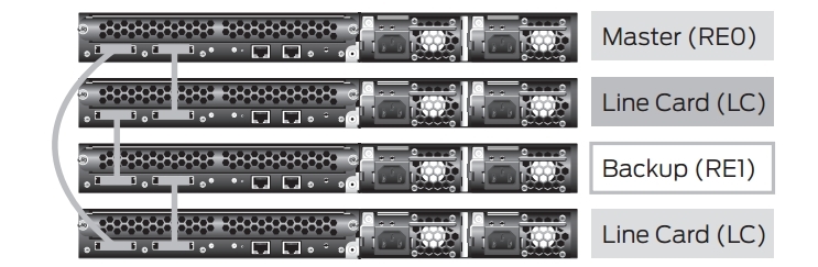
Or
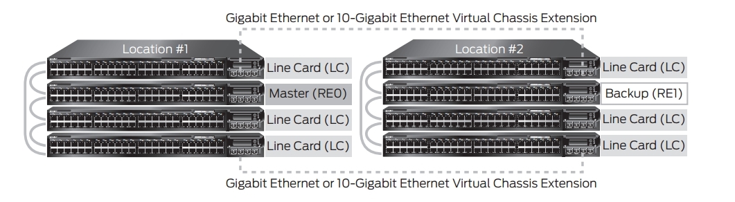
If the elements of the virtual chassis are separated geographically, then you should use the scheme below:
Recommended Virtual Chassis Topologies
The following figures show virtual chassis topologies that can be deployed based on specific user needs. The “ring” topology is the most commonly used, but the virtual chassis can also be deployed in a “Full mesh” topology or a multiple ring topology. The ring topology is recommended when deploying a virtual chassis in mixed mode.
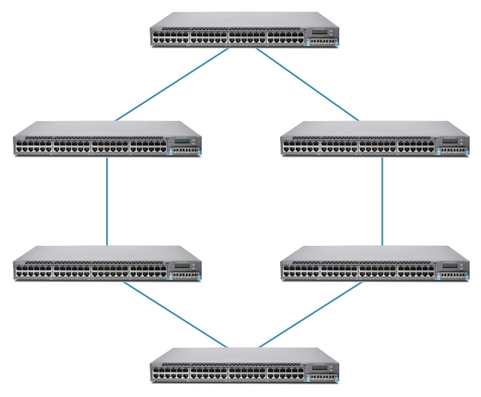
Ring
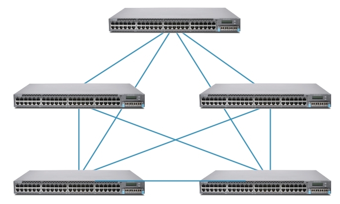
Full mesh
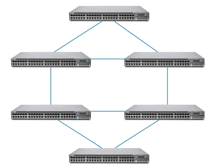
Multiple Ring Topology
Configuring Virtual Chassis
Virtual chassis configuration occurs at the hierarchy level [edit virtual-chassis]
{master: 0} [edit virtual-chassis]
user @ switch # set?
Possible completions:
+ apply-groups Groups from
+ apply-groups-except
> auto-sw-update Auto software update
> fast-failover fast failover mechanism
id Virtual Chassis identifier, of type ISO system id
> MAC-address when member leaves virtual chassis
> member Member of Virtual Chassis configuration
no-split-detection Disable split detection. Only recommended in a 2 member setup
preprovisioned Only accept preprovisioned members
> traceoptions Global tracing options for Virtual Chassis
To minimize traffic interruptions during the RE failover scenario, you need to enable graceful Routing Engine switchover.
{master: 0} [edit chassis]
user @ switch # set redundancy graceful-switchover?
Possible completions:
> graceful-switchover Enable graceful switchover on supported hardware
There are several options: dynamic and preprovisioning.
Dynamic:
1. Turn on the master switch and set the ID 0 and priority 255.
2. Connect the backup switch and set the ID 0 and priority 255.
{master: 0} [edit virtual-chassis]
user @ Switch-1 # set member < member-id > mastership-priority < priority >
3. When using only two switches, it is recommended to disable split detection.
[edit virtual-chassis]
user @ switch # set no-split-detection
4. Turn on the power on the other switches.
5. If we use a mixed virtual chassis, then we add the command:
user @ device> request virtual-chassis mode mixed reboot
6. On each individual switch, we indicate the ports that will be in the role of VCPs.
Preprovisioning
1. Turn on the master switch (pre-collect all the serial numbers of the switches that will be in the cluster).
2. If we will use a mixed virtual chassis:
user @ device> request virtual-chassis mode mixed reboot
3. Optionally configure the IP address on the management interface:
user @ switch # set interfaces vme unit 0 family inet address / ip-address / mask /
4. Install Preprovisioning mode:
[edit virtual-chassis]
user @ switch # set preprovisioned
5. Register the role, ID for each member of the virtual chassis
[edit virtual-chassis]
user @ switch # set member 0 serial number BM0208105168 role routing-engine
user @ switch # set member 1 serial number BM0208124111 role line-card
user @ switch # set member 2 serial number BM0208124231 role routing-engine
user @ switch # set member 3 serial number BM0208124333 role line-card
6. When using only two switches, it is recommended to disable split detection.
[edit virtual-chassis]
user @ switch # set no-split-detection
7. Turn on the remaining members of the virtual chassis.
8. If we use a mixed virtual chassis, then we introduce on each switch
user @ device> request virtual-chassis mode mixed reboot
9. Specify which interfaces we will use as VCPs.
user @ switch> request virtual-chassis vc-port set pic-slot pic-slot-number port port-number local
For example, to use the onboard 40G ports on an EX4600 switch.
user @ switch> request virtual-chassis vc-port set pic-slot 2 port 0 local
Where port 0 is the first 40G integrated port.
user @ switch> request virtual-chassis vc-port set pic-slot pic-slot-number port port-number local
Monitoring Virtual chassis
To monitor the virtual chassis, use the show virtual-chassis command with various keys:
{master: 0}
user @ switch> show virtual-chassis?
Possible completions:
<[Enter]> Execute this command
active topology Virtual chassis active topology
device-topology PFE device topology
fast failover fast failover status
login
protocol Show Virtual Chassis protocol information
status Virtual Chassis information
vc-path Show virtual-chassis packet path
vc-port Virtual Chassis port information
| Pipe through a command
Checking the status of virtual chassis ports:
show virtual-chassis vc-port
{master: 0}
user @ Switch-1> show virtual-chassis vc-port
fpc0:
- Interface Type Trunk Status Speed Neighbor
or ID (mbps) ID Interface
PIC / Port
vcp-0 Dedicated 2 Up 32000 1 vcp-0
vcp-1 Dedicated 1 Up 32000 1 vcp-1
fpc1:
- Interface Type Trunk Status Speed Neighbor
or ID (mbps) ID Interface
PIC / Port
vcp-0 Dedicated 2 Up 32000 0 vcp-0
vcp-1 Dedicated 1 Up 32000 0 vcp-1
Checking status information:
show virtual-chassis status
{master: 0}
user @ Switch-1> show configuration virtual-chassis
preprovisioned;
member 0 {
role routing-engine;
serial number BM0208105168;
}
member 1 {
role line card;
serial number BM0208124231;
}
{master: 0}
user @ Switch-1> show virtual-chassis status
Preprovisioned Virtual Chassis
Virtual Chassis ID: 8d5c.a77f.8de8
Mastership Neighbor List
Member ID Status Serial No Model Priority Role ID Interface
0 (FPC 0) Prsnt BM0208105168 ex4200-24t 129 Master * 1 vcp-0
1 vcp-1
1 (FPC 1) Prsnt BM0208124231 ex4200-24t 0 Linecard 0 vcp-0
0 vcp-1
So we briefly reviewed the Virtual chassis technology, options for setting up and monitoring.
One of the main advantages of Juniper solutions over its competitors is their stacking capabilities. There are quite a few options, starting from the base Virtual Chassis and ending with a variety of data center technologies.
Part 1. Virtual Chassis
')
Consider the capabilities and features of the Virtual Chassis base technology, which allows you to combine up to 10 devices (depending on the model) of the EX series and QFX series into one logical device, as well as how to configure and monitor it.
To begin with, which models support the technology of Virtual Chassis:
• EX2200 Ethernet Switch up to 4 devices
• EX3300 Ethernet Switch up to 10 devices
• EX4200 Ethernet Switch up to 10 devices
• EX4300 Ethernet Switch up to 10 devices
• EX4550 Ethernet Switch up to 10 devices
• EX4600 Ethernet Switch up to 10 devices
• QFX5100 Switch up to 10 devices.
These are the models that at the time of this writing are produced and available for order, and, accordingly, can be used in the virtual chassis.
Virtual Chassis technologies combine the scalability and compact form factor of freestanding switches with high availability, bandwidth and port density of traditional chassis. Virtual Chassis allows you to provide cost-effective deployment of switches and network availability in places where the cost of installing chassis devices may be too high, or where it is physically impossible to install chassis switches.
Due to the fact that several devices are managed as a single unit, Virtual Chassis allows you to use the same redundancy capabilities as the use of several Routing Engine (RE) in chassis switches, including graceful Routing Engine switchover (GRES) technology.
To connect to a virtual chassis, specialized interfaces can be used that are on the EX4500, EX4550, and EX4200 devices, as well as copper and optical ports. Ports that are used to connect to a virtual chassis are called Virtual Chassis Ports (VCP). For example, in an EX2200-24T-4G 24 10/100 / 1000Base-T and 4 SFP switch, you can use either SFP or copper ports to connect to a virtual chassis. This allows you to spread the members of a single virtual chassis over a distance of 80 km.
Mixed Virtual Chassis makes it possible to use switches of different series and even different lines within one virtual chassis, as shown in the figure below.
Options for stacking switches in Mixed Virtual Chassis
In the virtual chassis there is a separation by roles: two switches get the role RE0 and RE1, and the rest are used as line cards.
RE0 performs the role of a master whose task is to manage the remaining members of the virtual chassis, and it is he who is responsible for creating the routing tables and distributing them across the line cards. It also stores configuration files. RE1 - backup, in case of RE0 failure.
Consider the distribution of switch roles in a virtual chassis using the example below.
Criteria for choosing a master:
- The switch with the highest priority. The priority can be from 1 to 255, by default it is 128 on all switches;
- A switch that was a master before rebooting;
- Switch with the highest uptime (the difference should be more than 1 min) ;.
- Switch with the lowest MAC address.
Each member of the virtual chassis receives its ID from 0 to 9. You can manually configure this ID from the wizard (whose ID is 0) (after rebooting, the number is saved and can serve as a slot number in the interface definition).
Due to the fact that the ID is assigned to the switch, the following situation may arise: when one switch fails and you change it, the new member receives not the number of the failed switch, but the next free or not connected to the virtual chassis, if all ID is already taken.
Therefore, in order to replace a failed switchboard with a new one, you first need to remove its ID from the wizard as follows:
{master: 0}
user @ Switch-1> request virtual-chassis recycle member-id <member-id>
Or you can do this with the command ID:
user @ host> request virtual-chassis renumber member-id <current-member-id> new-member-id <new-member-id>
Single management interface and single console
Within the virtual chassis, all management interfaces are merged into one, with a single IP address:
{master: 0} [edit]
user @ switch # show interfaces vme
unit 0 {
family inet {
address 10.210.14.148/27;
}
}
{master: 0} [edit]
user @ Switch-1 # run show interfaces terse vme
Interface Admin Link Proto Local Remote
vme up up
vme.0 up up inet 10.210.14.148/27
The same thing happens with the console port, no matter what you connect to, you will be taken to RE0.
Software compatibility
All members of the virtual chassis must be with the same version of the software. When we add a new switch to the virtual chassis, the wizard checks its version of the software; if the software is different, the new switch will receive an ID, but will not become an active member of the virtual chassis. To do this, you need to update the software on the new switch with the command:
request system software add member <member-id> reboot
This command downloads the image from the master switch through the VCPs of the new switch, and then reboots it, and the new switch may not be connected directly to the main switch.
Automatic software update
By configuring the automatic software update, when each new switch is connected to a version other than the wizard, its software will be automatically updated. set virtual-chassis auto-sw-update package-name <package-name>
Nonstop Software Upgrade
The Nonstop software upgrade (NSSU) technology allows you to upgrade software on all members of a virtual chassis with minimal loss. For this technology to work correctly, you need to:
- All members of the virtual chassis were connected to the “ring” topology;
- Master and backup were adjacent;
- Line cards have been configured in preconfiguration mode;
- On all members of the virtual chassis should be one version of the software;
- NSR and GRES should be included; Optionally, you can activate the NSB command request system snapshot.
NSSU process:
- Download the image of the software. If you use a mixed virtual chassis, then download both images.
- Copy it to RE0, recommended in the / var / tmp folder,
- From the command line RE0, launch NSSU with the command:
request system software nonstop-upgrade /var/tmp/package-name.tgz
or for mixed virtual chassis
request system software nonstop-upgrade set [/var/tmp/package-name.tgz /var/tmp/package-name.tgz]
Recommended Master Switch and Backup Switch Location
When building a virtual chassis, the following connection schemes are recommended:
Or
If the elements of the virtual chassis are separated geographically, then you should use the scheme below:
Recommended Virtual Chassis Topologies
The following figures show virtual chassis topologies that can be deployed based on specific user needs. The “ring” topology is the most commonly used, but the virtual chassis can also be deployed in a “Full mesh” topology or a multiple ring topology. The ring topology is recommended when deploying a virtual chassis in mixed mode.
Ring
Full mesh
Multiple Ring Topology
Configuring Virtual Chassis
Virtual chassis configuration occurs at the hierarchy level [edit virtual-chassis]
{master: 0} [edit virtual-chassis]
user @ switch # set?
Possible completions:
+ apply-groups Groups from
+ apply-groups-except
> auto-sw-update Auto software update
> fast-failover fast failover mechanism
id Virtual Chassis identifier, of type ISO system id
> MAC-address when member leaves virtual chassis
> member Member of Virtual Chassis configuration
no-split-detection Disable split detection. Only recommended in a 2 member setup
preprovisioned Only accept preprovisioned members
> traceoptions Global tracing options for Virtual Chassis
To minimize traffic interruptions during the RE failover scenario, you need to enable graceful Routing Engine switchover.
{master: 0} [edit chassis]
user @ switch # set redundancy graceful-switchover?
Possible completions:
> graceful-switchover Enable graceful switchover on supported hardware
There are several options: dynamic and preprovisioning.
Dynamic:
1. Turn on the master switch and set the ID 0 and priority 255.
2. Connect the backup switch and set the ID 0 and priority 255.
{master: 0} [edit virtual-chassis]
user @ Switch-1 # set member < member-id > mastership-priority < priority >
3. When using only two switches, it is recommended to disable split detection.
[edit virtual-chassis]
user @ switch # set no-split-detection
4. Turn on the power on the other switches.
5. If we use a mixed virtual chassis, then we add the command:
user @ device> request virtual-chassis mode mixed reboot
6. On each individual switch, we indicate the ports that will be in the role of VCPs.
Preprovisioning
1. Turn on the master switch (pre-collect all the serial numbers of the switches that will be in the cluster).
2. If we will use a mixed virtual chassis:
user @ device> request virtual-chassis mode mixed reboot
3. Optionally configure the IP address on the management interface:
user @ switch # set interfaces vme unit 0 family inet address / ip-address / mask /
4. Install Preprovisioning mode:
[edit virtual-chassis]
user @ switch # set preprovisioned
5. Register the role, ID for each member of the virtual chassis
[edit virtual-chassis]
user @ switch # set member 0 serial number BM0208105168 role routing-engine
user @ switch # set member 1 serial number BM0208124111 role line-card
user @ switch # set member 2 serial number BM0208124231 role routing-engine
user @ switch # set member 3 serial number BM0208124333 role line-card
6. When using only two switches, it is recommended to disable split detection.
[edit virtual-chassis]
user @ switch # set no-split-detection
7. Turn on the remaining members of the virtual chassis.
8. If we use a mixed virtual chassis, then we introduce on each switch
user @ device> request virtual-chassis mode mixed reboot
9. Specify which interfaces we will use as VCPs.
user @ switch> request virtual-chassis vc-port set pic-slot pic-slot-number port port-number local
For example, to use the onboard 40G ports on an EX4600 switch.
user @ switch> request virtual-chassis vc-port set pic-slot 2 port 0 local
Where port 0 is the first 40G integrated port.
user @ switch> request virtual-chassis vc-port set pic-slot pic-slot-number port port-number local
Monitoring Virtual chassis
To monitor the virtual chassis, use the show virtual-chassis command with various keys:
{master: 0}
user @ switch> show virtual-chassis?
Possible completions:
<[Enter]> Execute this command
active topology Virtual chassis active topology
device-topology PFE device topology
fast failover fast failover status
login
protocol Show Virtual Chassis protocol information
status Virtual Chassis information
vc-path Show virtual-chassis packet path
vc-port Virtual Chassis port information
| Pipe through a command
Checking the status of virtual chassis ports:
show virtual-chassis vc-port
{master: 0}
user @ Switch-1> show virtual-chassis vc-port
fpc0:
- Interface Type Trunk Status Speed Neighbor
or ID (mbps) ID Interface
PIC / Port
vcp-0 Dedicated 2 Up 32000 1 vcp-0
vcp-1 Dedicated 1 Up 32000 1 vcp-1
fpc1:
- Interface Type Trunk Status Speed Neighbor
or ID (mbps) ID Interface
PIC / Port
vcp-0 Dedicated 2 Up 32000 0 vcp-0
vcp-1 Dedicated 1 Up 32000 0 vcp-1
Checking status information:
show virtual-chassis status
{master: 0}
user @ Switch-1> show configuration virtual-chassis
preprovisioned;
member 0 {
role routing-engine;
serial number BM0208105168;
}
member 1 {
role line card;
serial number BM0208124231;
}
{master: 0}
user @ Switch-1> show virtual-chassis status
Preprovisioned Virtual Chassis
Virtual Chassis ID: 8d5c.a77f.8de8
Mastership Neighbor List
Member ID Status Serial No Model Priority Role ID Interface
0 (FPC 0) Prsnt BM0208105168 ex4200-24t 129 Master * 1 vcp-0
1 vcp-1
1 (FPC 1) Prsnt BM0208124231 ex4200-24t 0 Linecard 0 vcp-0
0 vcp-1
So we briefly reviewed the Virtual chassis technology, options for setting up and monitoring.
Source: https://habr.com/ru/post/283546/
All Articles