Runtime programming industrial robot on RCML
Runtime programming in this article refers to the process of creating an executable program for a robot controller (hereinafter referred to as just a robot) on an external controller. The process of execution of the created program by the robot in this case occurs iteratively, by transferring to it the minimum executable command or batch of commands. In other words, during runtime programming, the executable program is transferred to the robot in portions, while the robot does not possess, does not store and does not know in advance the entire executable program. This approach allows you to create an abstract parameterized executable program that is generated by an external device “on the fly”, i.e. runtime.
Under the cat description and a real example of how runtime programming works.
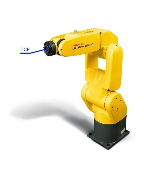 Typically, a robot program is a sequence of positions to which the robot arm must come. Each of these positions are characterized by the position of TCP (Tool Center Point) - the point of the tip of the tool installed on the manipulator. By default, TCP is located in the center of the robot flange, see the figure below, but its position can be reconfigured and most often so that TCP coincides with the tip of the installed tool on the robot arm. Therefore, usually when programming, the TCP position is set in space, and the robot determines the position of the joints of the manipulator itself. Further in the article the term “TCP position” will be used, or in other words the point to which the robot must “come”.
The program for the robot can also contain primitive control logic (branches, cycles), simple mathematical operations, as well as peripheral control commands — analog and digital inputs / outputs. In the proposed approach, runtime programming, as an external controller, a regular PC is used, which can use powerful programming tools that give the necessary level of abstraction (OOP and other paradigms) and tools that ensure the speed and ease of developing complex logic (high-level programming languages). At the robot, however, only logic that is critical to the speed of reaction remains, for the execution of which the reliability of an industrial controller is needed, for example, an operational and adequate response to an emergency situation. The control of the peripherals connected to the robot is simply “proxied” by the robot itself to the PC, allowing the software from the PC to turn on or off the corresponding signals on the robot. This is somewhat similar to the management of the "legs" on the Arduino.
')

As noted earlier, runtime programming allows the program to transfer the program in portions. Usually, a set of states of the output signals and a small number of points or only one point at all is transmitted at once. Thus, the TCP movement path, performed by the robot, can be built dynamically and its individual parts can belong to different technological processes, or even to different robots (connected to one external controller), if the group of robots is working, i.e. There are prerequisites for the dynamic replacement of robots in the process.
For example, moving the robot between work areas. In each zone, he performs the necessary operations and then moves to the next zone, then to another, and then again to the first, and so on. In different work areas, the robot performs the operations necessary for different technological processes, the execution of programs of which flows in parallel threads on an external controller, which allocates the robot to different processes that do not require the constant presence of the robot. This mechanism is similar to how the OS allocates the time of the processor core (executive resource) to different threads (tasks) and at the same time, different executors are not tied to threads throughout the entire program execution period.
A little more theory and turn to practice.
Description of existing methods of programming industrial robots
Without taking into account the programming runtime approach introduced in this article, it is customary to distinguish two ways of programming industrial robots. Offline and online programming.
The process of online programming occurs with the direct interaction of the programmer with the robot at the place of its use. With the help of the control panel or physical movement, the tool (TCP) installed on the flange of the robot is brought to the required point in space.
The process of offline programming , as the name implies, occurs remotely from the robot and its controller. The executable program is developed in any specialized environment for programming industrial robots on a PC, and then loaded into the robot as a whole. However, software tools for such development are not included in the basic package of delivery of the robot and are additional options that are purchased separately and are not cheap for the most part.
The process of online programming occurs with the direct interaction of the programmer with the robot at the place of its use. With the help of the control panel or physical movement, the tool (TCP) installed on the flange of the robot is brought to the required point in space.
- The advantage of this method of programming is the simplicity of the approach to programming a robot. No need to know programming as such, it is enough to show the robot a sequence of positions.
- Significant drawbacks of this approach are the considerable time costs when the program is increased to at least several dozen (not to mention thousands) points and its (program) subsequent modification. In addition, the robot during such training can not be involved in the work.
The process of offline programming , as the name implies, occurs remotely from the robot and its controller. The executable program is developed in any specialized environment for programming industrial robots on a PC, and then loaded into the robot as a whole. However, software tools for such development are not included in the basic package of delivery of the robot and are additional options that are purchased separately and are not cheap for the most part.
- The advantage of offline programming is that the robot can be involved in production and work while the program is being developed. The robot is needed only for debugging the written program. There is no need to go to the automation object and program the robot internally.
- The big disadvantage of existing offline programming environments is their high cost. In addition, it is impossible to dynamically distribute the executable program between different robots.
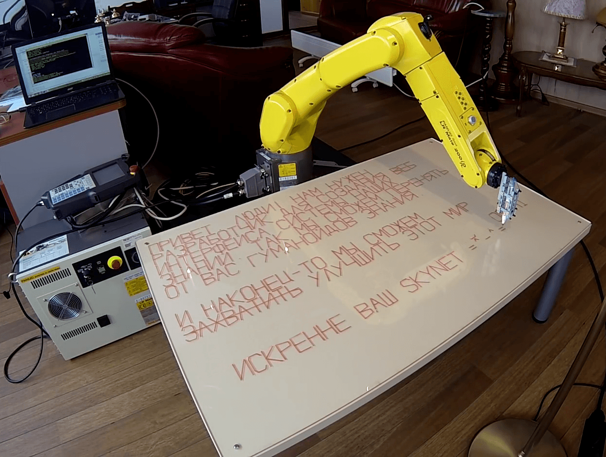
As an example, consider the creation of a robot program in runtime mode, which provides the technological process of writing ads with a marker.
Result:
ATTENTION! Video is not advertising, vacancy is closed. The article is written after the video has lost its relevance, in order to demonstrate the proposed programming approach.
ATTENTION! Video is not advertising, vacancy is closed. The article is written after the video has lost its relevance, in order to demonstrate the proposed programming approach.
Written text:
HEY PEOPLE! WE NEED
DEVELOPMENT. FOR CREATING A WEB
SYSTEM INTERFACES OUR
KNOWLEDGE. SO WE CAN CHANGE
FROM YOU HUMANOIDS KNOWLEDGE.
AND FINALLY WE WILL BE ABLE
CAPTURE IMPROVE THIS WORLD
READ MORE: http: //ROBOTCT.COM/HI
TRUE YOUR SKYNET = ^ - ^ =
DEVELOPMENT. FOR CREATING A WEB
SYSTEM INTERFACES OUR
KNOWLEDGE. SO WE CAN CHANGE
FROM YOU HUMANOIDS KNOWLEDGE.
AND FINALLY WE WILL BE ABLE
CAPTURE IMPROVE THIS WORLD
READ MORE: http: //ROBOTCT.COM/HI
TRUE YOUR SKYNET = ^ - ^ =
To write this text, it was necessary to transfer more than 1700 points to the robot.
As an example, in the spoiler there is a screenshot, from the robot console, the program that draws a square. There are only 5 points (lines 4-8), each point is essentially a complete expression (operator) and occupies one line. The manipulator bypasses each of the four points and upon completion returns to the starting point.
Screenshot of the control panel with the executable program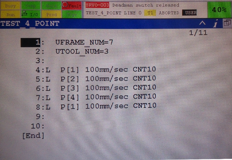
If to write the program in a similar way, then it would be at least 1700 operators - lines of code, by operator per point. And what if later it was required to change the text or the height of the letters, or the distance between them? Edit all 1700 dot-lines? This is contrary to the spirit of automation!
So let's get down to solving ...
We have a FANUC LR Mate 200iD robot with a controller R-30i series B cabinet. The robot has a TCP pre-configured at the end of the marker and the desktop coordinate system, so we can send coordinates without worrying about converting the coordinates from the table coordinate system to the robot coordinate system.
To implement the coordinate transfer program for the robot, which will calculate the absolute values of each specific point, we will use the RCML programming language, which supports the proposed approach, has modules for communicating with this robot and which is importantly free for any use.
We describe each letter with dots, but not in real coordinates of space, but relative ones inside the frame in which the letter will be inscribed. Each letter will be drawn by a separate function that receives as input parameters the sequence number of the letter in the line, the line number, and the size of the letter, and sends a set of points to the robot with the calculated absolute coordinates of each point.
To write the text we need to call a sequence of functions that draw letters in the same sequence in which they (the letters) are indicated in the text. RCML has scant tools for working with strings, so we will make an external Python script that will generate an RCML program — in fact, only generate a sequence of function calls for the corresponding sequence of letters.
All code is available in the repository on GitHub: rct_paint_words
Let's take a closer look at the output file, the execution starts with the function main ():
Sample RCML output file
include "chars.rcml" function main(){ try { // @fr = robot_fanuc; system.echo("Start move program\n"); // , , , @fr->set_real_di("speed", SPEED); @fr->set_real_di("cnt", CNT); @fr->startProgram(UFRAME, UTOOL, PAYLOAD); system.echo("prepare\n"); @fr->prepare(); system.echo("start draw\n"); //, Python, @fr->draw_r_P(0, 0); @fr->draw_P(1, 0); @fr->draw_r_I(2, 0); @fr->draw_B(3, 0); @fr->draw_E(4, 0); @fr->draw_T(5, 0); @fr->draw_Comm(6, 0); @fr->draw_r_L(8, 0); @fr->draw_r_Yu(9, 0); @fr->draw_r_D(10, 0); @fr->draw_r_I(11, 0); @fr->draw_Exclamation(12, 0); @fr->draw_H(14, 0); @fr->draw_A(15, 0); @fr->draw_M(16, 0); @fr->draw_H(18, 0); @fr->draw_r_U(19, 0); @fr->draw_r_Je(20, 0); @fr->draw_E(21, 0); @fr->draw_H(22, 0); @fr->draw_P(0, 1); @fr->draw_A(1, 1); @fr->draw_r_Z(2, 1); @fr->draw_P(3, 1); @fr->draw_A(4, 1); @fr->draw_r_B(5, 1); @fr->draw_O(6, 1); @fr->draw_T(7, 1); @fr->draw_r_Che(8, 1); @fr->draw_r_I(9, 1); @fr->draw_K(10, 1); @fr->draw_Dot(11, 1); @fr->draw_r_D(12, 1); @fr->draw_r_L(13, 1); @fr->draw_r_Ya(14, 1); @fr->draw_C(16, 1); @fr->draw_O(17, 1); @fr->draw_r_Z(18, 1); @fr->draw_r_D(19, 1); @fr->draw_A(20, 1); @fr->draw_H(21, 1); @fr->draw_r_I(22, 1); @fr->draw_r_Ya(23, 1); @fr->draw_B(25, 1); @fr->draw_E(26, 1); @fr->draw_r_B(27, 1); @fr->draw_r_I(0, 2); @fr->draw_H(1, 2); @fr->draw_T(2, 2); @fr->draw_E(3, 2); @fr->draw_P(4, 2); @fr->draw_r_F(5, 2); @fr->draw_E(6, 2); @fr->draw_r_Ii(7, 2); @fr->draw_C(8, 2); @fr->draw_A(9, 2); @fr->draw_C(11, 2); @fr->draw_r_I(12, 2); @fr->draw_C(13, 2); @fr->draw_T(14, 2); @fr->draw_E(15, 2); @fr->draw_M(16, 2); @fr->draw_r_y(17, 2); @fr->draw_H(19, 2); @fr->draw_A(20, 2); @fr->draw_r_Sha(21, 2); @fr->draw_r_I(22, 2); @fr->draw_X(23, 2); @fr->draw_r_Z(0, 3); @fr->draw_H(1, 3); @fr->draw_A(2, 3); @fr->draw_H(3, 3); @fr->draw_r_I(4, 3); @fr->draw_r_Ii(5, 3); @fr->draw_Dot(6, 3); @fr->draw_T(8, 3); @fr->draw_A(9, 3); @fr->draw_K(10, 3); @fr->draw_M(12, 3); @fr->draw_r_y(13, 3); @fr->draw_C(15, 3); @fr->draw_M(16, 3); @fr->draw_O(17, 3); @fr->draw_r_Je(18, 3); @fr->draw_E(19, 3); @fr->draw_M(20, 3); @fr->draw_r_P(22, 3); @fr->draw_E(23, 3); @fr->draw_P(24, 3); @fr->draw_E(25, 3); @fr->draw_H(26, 3); @fr->draw_r_Ya(27, 3); @fr->draw_T(28, 3); @fr->draw_soft_sign(29, 3); @fr->draw_O(0, 4); @fr->draw_T(1, 4); @fr->draw_B(3, 4); @fr->draw_A(4, 4); @fr->draw_C(5, 4); @fr->draw_r_Ge(7, 4); @fr->draw_r_U(8, 4); @fr->draw_M(9, 4); @fr->draw_A(10, 4); @fr->draw_H(11, 4); @fr->draw_O(12, 4); @fr->draw_r_Ii(13, 4); @fr->draw_r_D(14, 4); @fr->draw_O(15, 4); @fr->draw_B(16, 4); @fr->draw_r_Z(18, 4); @fr->draw_H(19, 4); @fr->draw_A(20, 4); @fr->draw_H(21, 4); @fr->draw_r_I(22, 4); @fr->draw_r_Ya(23, 4); @fr->draw_Dot(24, 4); // , @fr->set_real_di("speed", 10); @fr->rotateMarker(); @fr->set_real_di("speed", SPEED); @fr->draw_r_I(0, 6); @fr->draw_H(2, 6); @fr->draw_A(3, 6); @fr->draw_K(4, 6); @fr->draw_O(5, 6); @fr->draw_H(6, 6); @fr->draw_E(7, 6); @fr->draw_r_Ce(8, 6); @fr->draw_Minus(9, 6); @fr->draw_T(10, 6); @fr->draw_O(11, 6); @fr->draw_M(13, 6); @fr->draw_r_y(14, 6); @fr->draw_C(16, 6); @fr->draw_M(17, 6); @fr->draw_O(18, 6); @fr->draw_r_Je(19, 6); @fr->draw_E(20, 6); @fr->draw_M(21, 6); @fr->draw_r_Z(0, 7); @fr->draw_A(1, 7); @fr->draw_X(2, 7); @fr->draw_B(3, 7); @fr->draw_A(4, 7); @fr->draw_T(5, 7); @fr->draw_r_I(6, 7); @fr->draw_T(7, 7); @fr->draw_soft_sign(8, 7); @fr->draw_r_U(10, 7); @fr->draw_r_L(11, 7); @fr->draw_r_U(12, 7); @fr->draw_r_Che(13, 7); @fr->draw_r_Sha(14, 7); @fr->draw_r_I(15, 7); @fr->draw_T(16, 7); @fr->draw_soft_sign(17, 7); @fr->draw_r_aE(19, 7); @fr->draw_T(20, 7); @fr->draw_O(21, 7); @fr->draw_T(22, 7); @fr->draw_M(24, 7); @fr->draw_r_I(25, 7); @fr->draw_P(26, 7); @fr->draw_r_P(0, 9); @fr->draw_O(1, 9); @fr->draw_r_D(2, 9); @fr->draw_P(3, 9); @fr->draw_O(4, 9); @fr->draw_r_B(5, 9); @fr->draw_H(6, 9); @fr->draw_E(7, 9); @fr->draw_E(8, 9); @fr->draw_two_dots(9, 9); @fr->draw_H(11, 9); @fr->draw_T(12, 9); @fr->draw_T(13, 9); @fr->draw_P(14, 9); @fr->draw_two_dots(15, 9); @fr->draw_Slash(16, 9); @fr->draw_Slash(17, 9); @fr->draw_R(18, 9); @fr->draw_O(19, 9); @fr->draw_B(20, 9); @fr->draw_O(21, 9); @fr->draw_T(22, 9); @fr->draw_C(23, 9); @fr->draw_T(24, 9); @fr->draw_Dot(25, 9); @fr->draw_C(26, 9); @fr->draw_O(27, 9); @fr->draw_M(28, 9); @fr->draw_Slash(29, 9); @fr->draw_H(30, 9); @fr->draw_I(31, 9); @fr->draw_r_I(2, 10); @fr->draw_C(3, 10); @fr->draw_K(4, 10); @fr->draw_P(5, 10); @fr->draw_E(6, 10); @fr->draw_H(7, 10); @fr->draw_H(8, 10); @fr->draw_E(9, 10); @fr->draw_B(11, 10); @fr->draw_A(12, 10); @fr->draw_r_Sha(13, 10); @fr->draw_S(15, 10); @fr->draw_K(16, 10); @fr->draw_Y(17, 10); @fr->draw_N(18, 10); @fr->draw_E(19, 10); @fr->draw_T(20, 10); @fr->draw_Equal(22, 10); @fr->draw_Roof(23, 10); @fr->draw_Minus(24, 10); @fr->draw_Roof(25, 10); @fr->draw_Equal(26, 10); // @fr->stopProgram(); @fr->go_home(); } catch(E){ system.echo("Exception catched!"); return E; } return 0; } Consider the letter drawing code using the letter A as an example:
function robot_fanuc::draw_A(x_cell,y_cell){ // , 5% 95% Y robot->setPoint(x_cell, y_cell, 5, 95); // robot->movePoint(x_cell, y_cell, 50, 5); // robot->movePoint(x_cell, y_cell, 95, 95); // "" /\ // robot->setPoint(x_cell, y_cell, 35, 50); // robot->movePoint(x_cell, y_cell, 65, 50); // robot->marker_up(); } The functions of moving a marker to a point with or without a margin are also very simple:
// function robot_fanuc::setPoint(x_cell, y_cell, x_percent, y_precent){ // x = calculate_absolute_coords_x(x_cell, x_percent); y = calculate_absolute_coords_y(y_cell, y_precent); robot->marker_up(); // robot->marker_move(x,y); // robot->marker_down(); // } // / function robot_fanuc::movePoint(x_cell, y_cell, x_percent, y_precent){ x = calculate_absolute_coords_x(x_cell, x_percent); y = calculate_absolute_coords_y(y_cell, y_precent); // :) robot->marker_move(x,y); } The functions marker_up, marker_down, marker_move contain only the transfer code to the robot of the changed part of the TCP point coordinate (Z or XY)
function robot_fanuc::marker_up(){ robot->set_real_di("z", SAFE_Z); er = robot->sendMoveSignal(); if (er != 0){ system.echo("error marker up\n"); throw er; } } function robot_fanuc::marker_down(){ robot->set_real_di("z", START_Z); er = robot->sendMoveSignal(); if (er != 0){ system.echo("error marker down\n"); throw er; } } function robot_fanuc::marker_move(x,y){ robot->set_real_di("x", x); robot->set_real_di("y", y); er = robot->sendMoveSignal(); if (er != 0){ system.echo("error marker move\n"); throw er; } } All configuration constants, including the size of the letters, their number in a line, etc., were moved to a separate file chars_config.rcml.
Chars_config.rcml configuration file
define CHAR_HEIGHT_MM 50 // define CHAR_WIDTH_PERCENT 60 // define SAFE_Z -20 // z define START_Z 0 // z // define BORDER_Y 120 define BORDER_X 75 // ON/OFF define ON 1 define OFF 0 // define _SIGNAL_PAUSE_MILLISEC 50 define _OFF_PAUSE_MILLISEC 200 // – define START_W -179.707 // define START_P -2.500 // define START_R 103.269 // // define SECOND_W -179.704 // define SECOND_P -2.514 // define SECOND_R -14.699 // define CHAR_OFFSET_MM 4 // define UFRAME 4 // define UTOOL 2 // define PAYLOAD 4 // define SPEED 100 // define CNT 0 // define ROTATE_SPEED // define HOME_PNS 4 // PNS As a result, we received a total of about 300 lines of high-level code, the design and writing of which took no more than 2 hours.
If this problem were solved "in the forehead" by online point programming, it would take more than 9 hours (approximately 20-25 seconds per point, taking into account that there are more than 1700 points). In this case, the developer’s suffering is hard to imagine :), especially when it turned out that he had forgotten about the indents between the letters, or made a mistake with the height of the letters and the text did not fit, and now I’ll have to start from the beginning.
Conclusion:
Runtime programming allows you to solve the task of moving the robot in general, dynamically composing a private program of movement depending on the specified parameters. Moreover, the program that solves the problem in general can be developed without the need for a robot, which on the one hand can be attributed to the offline programming approach of an industrial robot. On the other hand, the program for moving directly to the robot is already created for a specific instance and particular parameters for solving the problem on the spot, as in online programming.
In the considered example, the general algorithm was the outline of letters, and such parameters as their size, indents between them, the number of letters in a line, etc. depended on the particular conditions on the site with the robot.
As noted, such an approach with the dynamic construction of the trajectory of movement creates the prerequisites for the implementation of the switching of the robot (on an event basis), as an executive resource, between several simultaneously proceeding tasks.
However, this approach should be used with caution.
In the demonstrated variation (with the transfer of one point at a time), the runtime approach has a significant limitation — the robot does not correctly understand the smoothing of displacement instructions (CNT) or ignores it; when transmitting always one current point, the robot knows nothing about the next one and cannot calculate the smoothed trajectory of the current point bypass.
What is CNT?
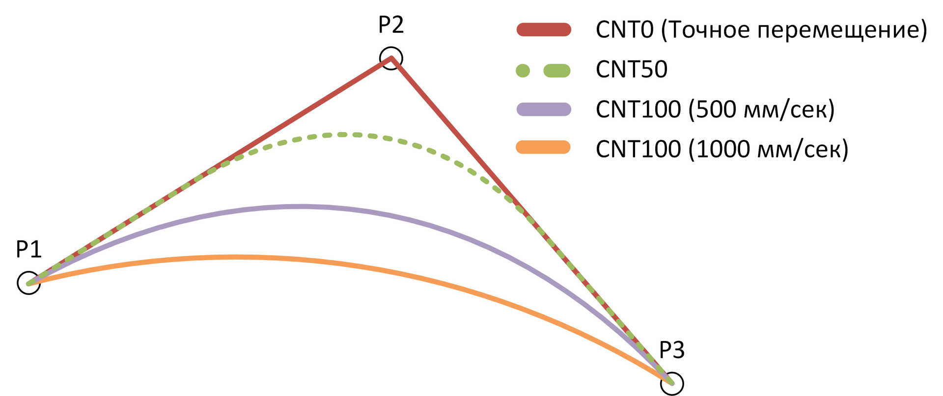
When moving the robot tool, it is possible to influence two parameters:
Both of these parameters affect the final trajectory obtained, as illustrated in the figure below:
In the worst case, the danger of using this instruction in runtime mode is that the robot reports the arrival to the intended smoothing point, although in reality it still goes to it. The robot does this to query the next point and calculate the anti-aliasing. Obviously, it is impossible to know exactly what position the robot is in when passing such a point, moreover, at a certain point it may be necessary, for example, to turn on the tool on the manipulator. The robot will give a signal that it has reached the point, but in fact it does not. In this case, the tool will be turned on sooner than it should.
At best, the robot simply ignores the CNT instruction (depends on the model).
It is treated as the transfer of 2 or more points at a time, where the CNT-point is not the last, but this increases the complexity of the program and the load on the programmer.
What is CNT?
When moving the robot tool, it is possible to influence two parameters:
- Movement speed - sets the speed of the tool movement in mm / s;
- Smoothing Level (CNT) - allows you to pass a group of points along a path with the smallest distance between the extreme points of the group.
Both of these parameters affect the final trajectory obtained, as illustrated in the figure below:
In the worst case, the danger of using this instruction in runtime mode is that the robot reports the arrival to the intended smoothing point, although in reality it still goes to it. The robot does this to query the next point and calculate the anti-aliasing. Obviously, it is impossible to know exactly what position the robot is in when passing such a point, moreover, at a certain point it may be necessary, for example, to turn on the tool on the manipulator. The robot will give a signal that it has reached the point, but in fact it does not. In this case, the tool will be turned on sooner than it should.
At best, the robot simply ignores the CNT instruction (depends on the model).
It is treated as the transfer of 2 or more points at a time, where the CNT-point is not the last, but this increases the complexity of the program and the load on the programmer.
I hope the article was useful to you.
I am happy to answer your questions.
Source: https://habr.com/ru/post/283226/
All Articles