Windows 10 IoT Core: GPIO, Lightning and RemoteClient
There are a huge number of examples and articles about Windows 10 IoT Core, telling about how easy and convenient to do with it a variety of devices. However, in reality, working with any "hardware" is always associated with a multitude of not very obvious nuances, the knowledge of which comes only with practice. I will talk about some of the features of working with GPIO on Raspberry Pi2 and Windows 10 IoT Core and at the same time about the new Remote Client feature available in the Insider Preview version.
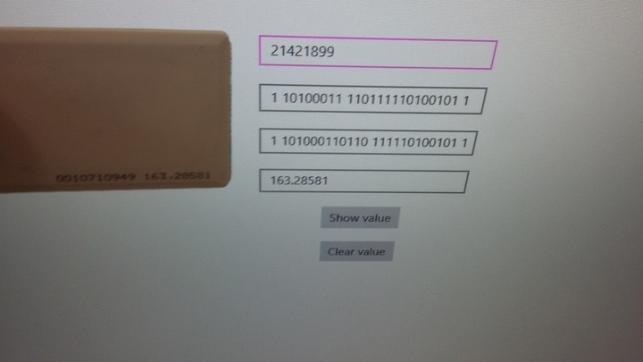
It all started with the fact that I needed to get the card number from the access control system (access control) reader. Almost all readers can transmit this data via the Wiegand interface. It consists of 3 wires: signal for transmission of units, signal for transmission of zeros and ground. In standby mode, on each signal wire is set to 5V. Data is transmitted by "reverse" pulses. Pulse width from 50 to 200 µs, period from 300 to 3000 µs:
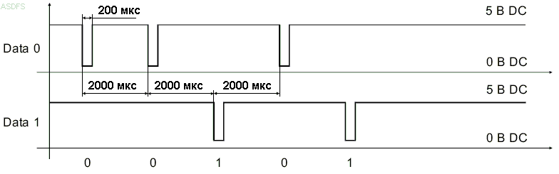
Data always goes in one direction from the reader to the controller. The number of bits can vary and their interpretation can also be different. The end of the package is determined by the timeout from 50 to 250 ms.
Such a spread of parameters occurred because this is a “historically established” interface that does not have a clear standard.
I got the device with the wiegand26 protocol - the package contains 26 bits in it, in which there are 2 bits of parity.
The task was given as part of the creation of a demonstration stand, so that one could experiment with the platform. Therefore, the Raspbery Pi2 with Windows 10 IoT Core on board came in very handy.
GPIO issues
To solve this problem in two ways:
- use interruptions when changing the voltage on pins
- use pins poll
The easiest was the first option. Having correctly initialized the pins, you can not load the processor with a constant poll, and only work out asynchronous calls. The code here is very simple:
var gpio = GpioController.GetDefault(); var data0 = gpio.OpenPin(data0Pin); var data1 = gpio.OpenPin(data1Pin); // Check if input pull-down resistors are supported if (data0.IsDriveModeSupported(GpioPinDriveMode.InputPullUp)) data0.SetDriveMode(GpioPinDriveMode.InputPullUp); else data0.SetDriveMode(GpioPinDriveMode.Input); if (data1.IsDriveModeSupported(GpioPinDriveMode.InputPullUp)) data1.SetDriveMode(GpioPinDriveMode.InputPullUp); else data1.SetDriveMode(GpioPinDriveMode.Input); var ticksPerMillisecond = TimeSpan.TicksPerMillisecond; var tenMs = ticksPerMillisecond / 1000; //1 data0.DebounceTimeout = TimeSpan.FromTicks(tenMs); data0.ValueChanged += data0_ValueChanged; data1.DebounceTimeout = TimeSpan.FromTicks(tenMs); data1.ValueChanged += data1_ValueChanged; Just need to say about DebounceTimeout. In general, it is not needed here, since, as a rule, during normal operation of the interface without significant interference, there is no “chatter” in it. But due to the fact that, in general, we do not know with which reader and under what conditions all this will work, I decided to experiment with this timeout.
But nothing good came of it. In the examples, DebounceTimeout is set in milliseconds everywhere, but for my case microseconds are needed. Whatever value I set, ValueChanged events did not appear. Therefore, the timeout had to be simply disabled, and everything began to work normally:
data0.DebounceTimeout = TimeSpan.FromTicks(0); data0.ValueChanged += data0_ValueChanged; data1.DebounceTimeout = TimeSpan.FromTicks(0); data1.ValueChanged += data1_ValueChanged; Data was read as follows:
private void data0_ValueChanged(GpioPin sender, pioPinValueChangedEventArgs e) { if (e.Edge == GpioPinEdge.FallingEdge) { UpdateValue(0); } } private void data1_ValueChanged(GpioPin sender, pioPinValueChangedEventArgs e) { if (e.Edge == GpioPinEdge.FallingEdge) { UpdateValue(1); } } Then it's time to solve the issue with the moment the parcel ends. As I wrote above, the end of the sending is considered to be the absence of pulses on both signal contacts for at least 50 ms. Here a timer would fit perfectly, which would regularly check if there was an exchange, and if not, would send the result further.
This approach worked poorly. I used ThreadPoolTimer, because the code had to work without UI. A feature of this timer is that every time its handler is called in a new thread. If the handler runs longer than the timer period, then another one will be launched in parallel, and then another one, and so on. In this case, in our handler, the timer must be reset to start a new reception. Therefore, it is a critical section and should not be executed simultaneously in more than one instance. Accordingly, short intervals of the timer could not be used.
Then it turned out that the long intervals also cannot be used, as well as the synchronization of the handler through the lock, since while the timer handler is running, ValueChanged events from the ports stop coming. It seems that these events are lower priority than timer handlers. Moreover, experiments have shown that events do not hang in the queue, but are simply silently discarded.
Therefore, whatever one may say, the use of the timer led to the loss of events from the GPIO and, as a result, to the loss of data. They could be reduced by adjusting the period of the timer and redistributing the calculations to ValueChanged. But absolute reliability cannot be achieved with such an approach even theoretically. In addition, it turned out that ValueChanged is taking too long to skip events and lose data.
I decided to use a thread instead of a timer. For synchronization, the queue was used, into which the bits that arrived in ValueChanged were added. The flow should sleep for a while, then check if there was an exchange during this time, and if it wasn’t, take the bits from the queue, collect the result from them and send further.
But nothing happened here. It was possible to assume that ValueChanged will not be called when the thread is running, but the fact that it is not called when the thread is sleeping is a surprise for me. As an analogue of Thread.Sleep, I used Task.Delay. I don’t know if other Tasks are doing this (judging by the documentation, Delay starts another Task with a timer), but events from GPIO block it all tightly.
In general, the GPIO driver for Windows 10 IoT is written so that it is almost impossible to use asynchronously, since its events have a low priority in the system.
Lightning
In the process of learning how to work with GPIO, I learned that there is another, faster driver that can be used on Windows 10 IoT Core. It is called Lightning and includes not only GPIO, but also work with ADC, I2C, PWM, SPI. Speed is achieved through direct memory access (direct memory access).
The driver is in the preview stage, but it is already included in the Windows 10 version of IoT Core Insider Preview. It should be used by those who lack the speed of the standard driver. I was hoping here to get a higher priority ValueChanged.
The link above has instructions on how to use it, BUT, it just will not work. The problem lies in the NuGet package. Everything is installed, but it's impossible to get through to the Microsoft.IoT.Lightning.Providers namespace. And the only mention that the problem can not be overcome, I found in this article . The author tells how to control the LEDs. In particular, he was faced with the slow work of PWM and corrected the situation through the use of Lightning.
It looks like this:
Third, you'll need to reference the Lightning SDK. According to the documentation, you just reference via NuGet. Unfortunately, this doesn't work as of v1.0.3-alpha. I had to download the Microsoft.IoT.Lightning.Providers C++ source, add the Microsoft.Iot.Lightning.Providers.vcxproj project to my solution, and then make a project reference. Incidentally, I contacted some folks at Microsoft, and they said a new nuget will be published shortly with binaries that will fix this issue. I was helped by the method described in the article. I also downloaded the sources, added the project file to the Solution and made a Reference to it. And what was my surprise when it turned out that the ValueChanged events in Lightning were not implemented ...
After that, I gave up the idea of using the asynchronous approach and decided to do a survey of the pins in the loop.
UPDATE: In the process of solving the problem, I asked the developers a question about ValueChanged. They replied that they would soon do everything. And they fulfilled their promise.
In addition, Microsoft.IoT.Lightning.Providers 1.0.0 appeared in NuGet, which makes Microsoft.IoT.Lightning.Providers visible.
The solution of the problem
As a result, the problem was solved by creating a cycle with a polling period of 10 μs of pins. At first there were concerns that the speed might not be enough, but it turned out that everything works fast enough even on a standard driver.
The code looks like this:
_data0 = gpio.OpenPin(data0Pin, GpioSharingMode.Exclusive); _data1 = gpio.OpenPin(data1Pin, GpioSharingMode.Exclusive); if (_data0.IsDriveModeSupported(GpioPinDriveMode.InputPullUp)) _data0.SetDriveMode(GpioPinDriveMode.InputPullUp); else _data0.SetDriveMode(GpioPinDriveMode.Input); if (_data1.IsDriveModeSupported(GpioPinDriveMode.InputPullUp)) _data1.SetDriveMode(GpioPinDriveMode.InputPullUp); else _data1.SetDriveMode(GpioPinDriveMode.Input); _task = Task.Run(() => TaskHandler()); In order not to block the execution of other threads, the loop is made inside Task:
private void TaskHandler() { var ticksPerMillisecond = TimeSpan.TicksPerMillisecond; var mks = ticksPerMillisecond / 1000; //1 while (!_stopTask) { Task.Delay(TimeSpan.FromTicks(mks*10)).Wait(); var dt0 = _data0.Read(); var dt1 = _data1.Read(); ..... } } It works stably, but on the condition that the cards are brought to the reader no more than once per second.
This project with all the instructions on connecting the reader to the Raspberry Pi2, I plan to post a couple of weeks on GitHub.
Remote client
Many developers using Windows 10 IoT Core note that they really lack remote desktop. A monitor or TV is not always at hand, and it is not always convenient to use them. Finally, this space was closed and, starting with version 10.0.14295.1000, a remote client appeared . Now this and a newer version is available as Insider Preview .
Everything works very simply. On the Windows 10 IoT Core side, you need to allow remote client connection in the web interface: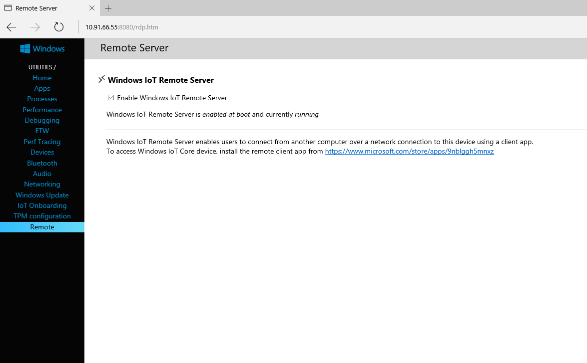
Install the client itself
Launch it and connect with Windows IoT Core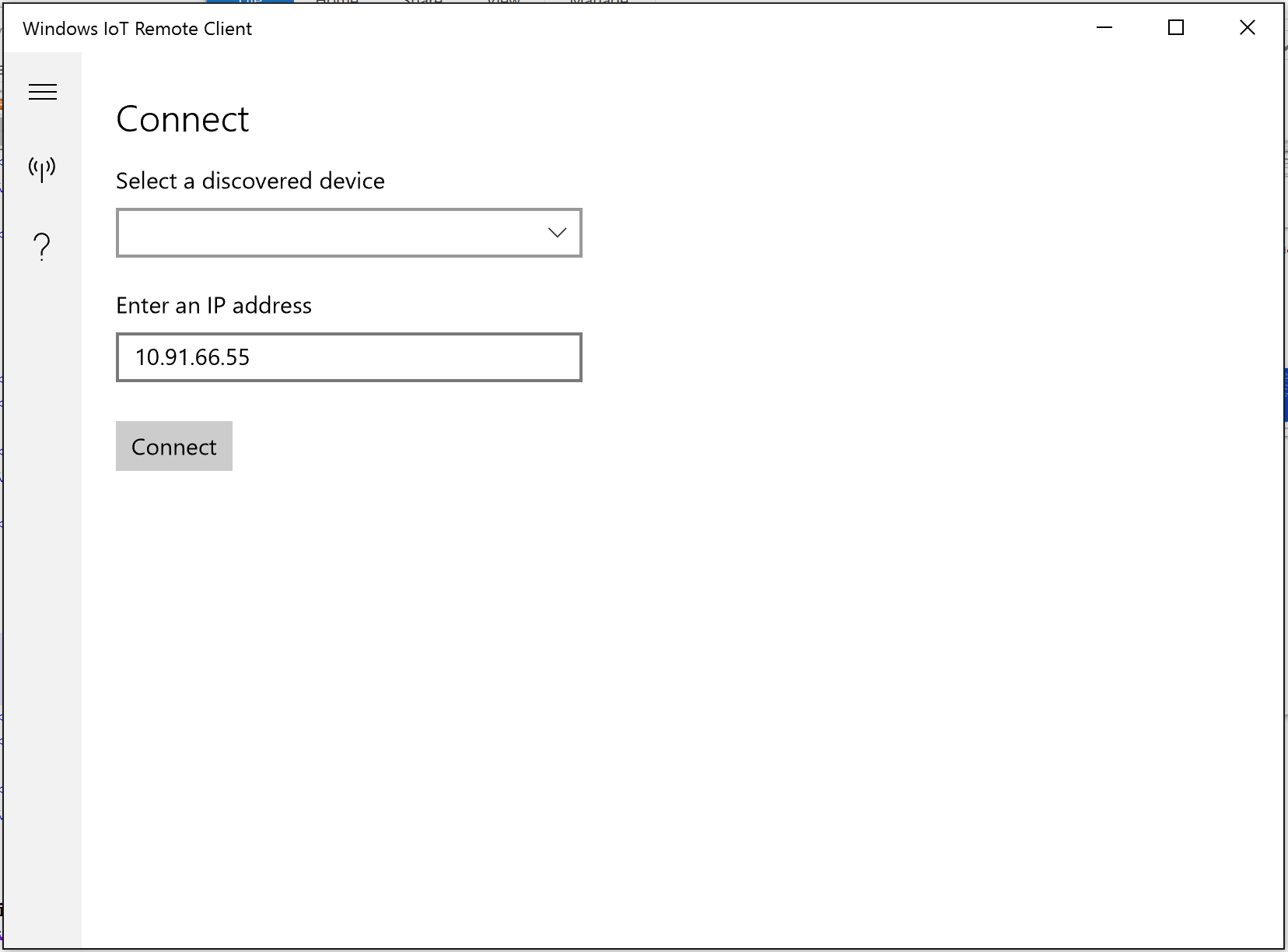
The instructions state that everything works well on the Raspberry Pi 2 and 3, Minnowboard Max and Dragonboard. At the same time, the performance of Pi2 is slightly lower, since there is no support for the GPU.
I just had a Rapberry Pi2.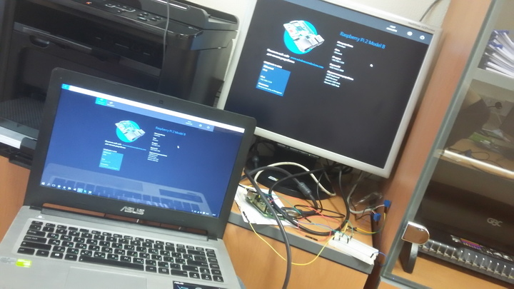
There are small delays, but, in my opinion, they are not critical. At the same time everything works stably and without problems.
findings
Summarizing all the above, I note that Windows 10 IoT Core does not always work the way a person who is used to microcontrollers can expect from it. Still, it is a full-fledged operating system, which is quite strongly abstracted from the "iron":
- The priority of events from GPIO is extremely low. Yes, and the mechanism of events is not entirely clear.
- Difficulties with asynchronous programming, not directly related to the work of interrupts.
- The existing functionality is not always enough, and the one that is presented in the form of a preview does not always work correctly. Although all this is developing very quickly.
- The performance of Windows 10 IoT Core is enough for tasks that are time-sensitive. In this case, there is still a reserve in the form of Lightning.
- A Remote Client appeared, which significantly improved the usability.
')
Source: https://habr.com/ru/post/283184/
All Articles