Using arduino to automate device testing
Our company "RTL Service" is developing a local positioning system, with which you can accurately determine where a certain person is in the room. In addition, our system allows you to contact this person using your own communicators (Figure 1) via a secure communication channel.
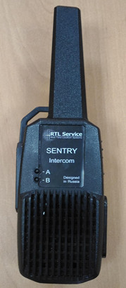
Fig. 1 - communicator
I am a testing department engineer, and it is my responsibility to check that the firmware and stuffing of our communicators faithfully work out various combinations of key presses and key presses. Previously, this was done manually and it took a lot of time and effort (in the end, the fingers did not want to obey). Therefore, it was decided to replace human labor with automatic testing with the help of hardware.
')
The Arduino UNO board was chosen as a tester. It is quite simple and easy to use, it has a built-in ATMega328 microcontroller, 14 digital I / Os (6 of which can be used as PWM outputs), a 16 MHz crystal oscillator and a USB connector.
So let's get started.
The button board connects to the communicator circuit board. In the train there are four lines, three of which are responsible for 3 buttons, and the fourth is responsible for the ground. For testing, we made our own handkerchief for connecting the connector of the communicator buttons (Fig. 2) to the Arduino. There is, respectively, a cable for connecting a communication device to the board, 4 wires to the pins of the controller and an optocoupler to untie the buttons from the ground.
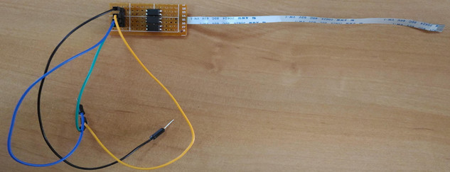
Fig. 2 - connection board
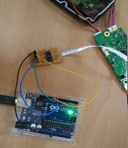
Fig.3 - how it all looks
Next is the program.
The communicator has 3 buttons: the environment / response request button, the channel change button on which the connection will be made, the device on / off button. Also, for example, simultaneously clamping the lower and upper buttons leads to an increase in the volume of the communicator, and clamping the lower and middle buttons to a decrease.
To press any button, you need to send to the corresponding pin 5 V (i.e., transfer the pin to the HIGH state). Thus, in order to release it, you need to stop feeding 5 V (set to LOW). For example, the device enable function:
In this function, a pin responsible for the bottom button is sent for 7 seconds (corresponds to the on / off time of the communication device) 5 V. After that, 0 V is sent, which means the release of the key.
In approximately the same way, it is possible to implement the process of clamping one key and pressing / clamping at this moment another:
In this function, the pin_1 button is clamped. At the same time point, the pin_2 button is pressed 10 and 60 times in a row, after which it is clamped for 10 and 60 seconds. In addition, there is a check for clamping the bottom button. It was stated above that when this button is pressed for more than 7 seconds, the communicator turns off / on, therefore, if this happens, the device must be returned to its original state.
There are also random keystrokes and keystrokes:
In these functions, one of three buttons is randomly selected, which is pressed or clamped for a random time.
The tests also checks the clamping of all keys. All combinations with different delays between clicks are checked, because this happens in life.
An additional advantage of this autotest, unlike manual, is that the device can be left for several days of continuous work, freeing the person for other tasks. Thus, it is possible to check the stability of the communicator under continuous load.
Using the above method, other devices can be tested. For example, you can simulate an unexpected power failure and see how quickly the device turns on.
In the next publication, we plan to talk about the organization of server stress testing, the implementation of external and internal server load, and the metrics we use to test the adequacy of the server’s work under load.
The author: Fedor Talayev
Fig. 1 - communicator
I am a testing department engineer, and it is my responsibility to check that the firmware and stuffing of our communicators faithfully work out various combinations of key presses and key presses. Previously, this was done manually and it took a lot of time and effort (in the end, the fingers did not want to obey). Therefore, it was decided to replace human labor with automatic testing with the help of hardware.
')
The Arduino UNO board was chosen as a tester. It is quite simple and easy to use, it has a built-in ATMega328 microcontroller, 14 digital I / Os (6 of which can be used as PWM outputs), a 16 MHz crystal oscillator and a USB connector.
So let's get started.
The button board connects to the communicator circuit board. In the train there are four lines, three of which are responsible for 3 buttons, and the fourth is responsible for the ground. For testing, we made our own handkerchief for connecting the connector of the communicator buttons (Fig. 2) to the Arduino. There is, respectively, a cable for connecting a communication device to the board, 4 wires to the pins of the controller and an optocoupler to untie the buttons from the ground.
Fig. 2 - connection board
Fig.3 - how it all looks
Next is the program.
The communicator has 3 buttons: the environment / response request button, the channel change button on which the connection will be made, the device on / off button. Also, for example, simultaneously clamping the lower and upper buttons leads to an increase in the volume of the communicator, and clamping the lower and middle buttons to a decrease.
To press any button, you need to send to the corresponding pin 5 V (i.e., transfer the pin to the HIGH state). Thus, in order to release it, you need to stop feeding 5 V (set to LOW). For example, the device enable function:
void switching(){ Serial.println("ON/OFF"); delay(70); digitalWrite(low_button, HIGH); delay(7000); digitalWrite(low_button, LOW); delay(500); }; In this function, a pin responsible for the bottom button is sent for 7 seconds (corresponds to the on / off time of the communication device) 5 V. After that, 0 V is sent, which means the release of the key.
In approximately the same way, it is possible to implement the process of clamping one key and pressing / clamping at this moment another:
void buttDelay_Press(int pin_1, int pin_2){ digitalWrite(pin_1, HIGH); delay(100); buttPress(1, pin_2,0,0,10);//press button buttPress(1, pin_2,0,0,60); digitalWrite(pin_2, HIGH); delay(10000); digitalWrite(pin_2, LOW); if (pin_2 == low_button ) { switching(); } digitalWrite(pin_2, HIGH); tDelay(60000); //change pin status to LOW if (pin_2 == low_button ) { switching(); } }; In this function, the pin_1 button is clamped. At the same time point, the pin_2 button is pressed 10 and 60 times in a row, after which it is clamped for 10 and 60 seconds. In addition, there is a check for clamping the bottom button. It was stated above that when this button is pressed for more than 7 seconds, the communicator turns off / on, therefore, if this happens, the device must be returned to its original state.
There are also random keystrokes and keystrokes:
// Random pressing void buttRandPress(int ncount){ for (int i = 0; i < ncount; i++) { rbutton = buttons[random(3)]; buttPress(1, rbutton,0,0, 1); } }; // Random holding void buttRandDelay(int ncount, int dtime){ for (int i = 0; i < ncount; i++) { rbutton = buttons[random(3)]; buttDelay(1, rbutton,0,0); tDelay(dtime); } }; In these functions, one of three buttons is randomly selected, which is pressed or clamped for a random time.
The tests also checks the clamping of all keys. All combinations with different delays between clicks are checked, because this happens in life.
An additional advantage of this autotest, unlike manual, is that the device can be left for several days of continuous work, freeing the person for other tasks. Thus, it is possible to check the stability of the communicator under continuous load.
Using the above method, other devices can be tested. For example, you can simulate an unexpected power failure and see how quickly the device turns on.
In the next publication, we plan to talk about the organization of server stress testing, the implementation of external and internal server load, and the metrics we use to test the adequacy of the server’s work under load.
The author: Fedor Talayev
Source: https://habr.com/ru/post/282163/
All Articles