Introduction to Shader Programming: Part 3
Having mastered the basics of working with shaders, we will try to practice to curb all the power of the GPU, creating a system of realistic dynamic lighting.

In the first lesson of this series we covered the basics of creating graphic shaders. In the second, we studied the general algorithm of actions when setting up shaders for any platform. Now it's time to understand the basic concepts from the field of graphic shaders without reference to the platform. For convenience, we will still use JavaScript / WebGL in the examples.
Before moving forward, make sure that you choose the most convenient way to work with shaders. The easiest option would be javascript / webgl, but I recommend trying your hand at your favorite platform.
')
Goals
By the end of this lesson you will not only be able to boast a deep understanding of the principle of operation of lighting systems, but also create such a system yourself from beginning to end.
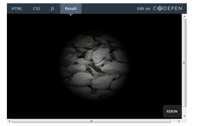
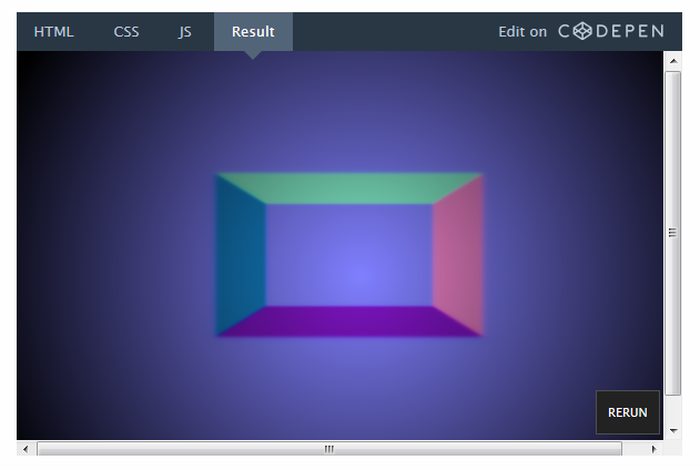
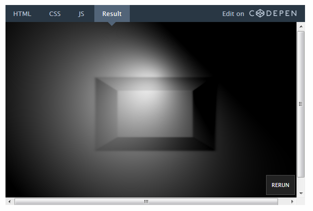
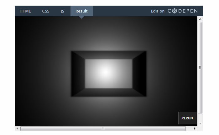
This is what the final result will look like ( go to CodePen to switch the lighting):
Despite the fact that ready-made lighting systems are built into many game engines, understanding their creation will help you apply more flexible settings and make your game more unique. The role of shader effects should not be reduced to a purely decorative: they can be used to create new game mechanics.
An excellent example of dynamic lighting is the Chroma game:
Getting Started: starting scene
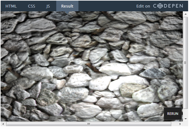
We will skip most of the preparations, since all of this was covered in the previous lesson. Let's start with a simple fragmentary shader with a texture:
So far, nothing special. JavaScript code sets the scene settings and sends the texture to the render, and the screen settings to the shader.
Declare variables in GLSL code:
It is necessary to adjust the coordinates of the pixels before using them to draw textures.
But first, let's do the following task to warm up.
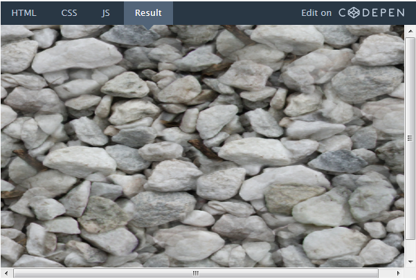
Task: Will you manage to display the texture, keeping its proportions? Try to do it yourself before proceeding to the solution below.
The reason why the texture is stretched is quite obvious. But here's a little hint: take a look at the line in which the coordinates are adjusted:
We divide vec2 by vec2, which is similar to dividing each component separately. In other words, the line above is equivalent to the following:
As we divide x and y into different numbers (width and height of the screen), naturally, the texture stretches.
But what would happen if we simply divided x and y from the variable gl_FragCoord by the value of x res? Or, on the contrary, the value of y res?
For simplicity, the experiment will leave everything as is until the end of the lesson. But, anyway, it is very important to understand what is happening in the code and why.
Step 1. Add a light source
First of all, let's add a light source. The light source is nothing more than a point that we send to the shader. Create a new uniform variable for this point:
We have created a vector with three parameters, since we will use the x and y values to indicate the position of the light source on the screen, and z as its radius.
Set the light source values in the JavaScript code:
Set the radius to 0.2, which corresponds to 20% of the screen size. However, the units do not play a special role, the size can be set in pixels. This does not affect anything until it comes to GLSL code.
Add an event listener to the JavaScript code to locate the mouse cursor:
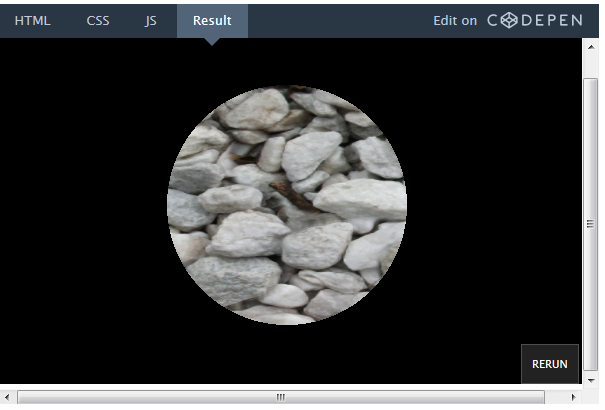
Now we write the shader code to make the light source work. Let's start with a simple one: let's make sure that all the pixels within the radius of light are visible, and all the others are black.
In the GLSL code, it will look something like this:
So, here is what we did:
• Declared a uniform variable for the light source.
• Used the built-in distance function to determine the distance between the light source and this pixel.
• Checked the value of the distance function (in pixels). If it is more than 20% of the screen width, we return the color of this pixel, if not, we return black.
See in action - on CodePen.
Oops! It seems that something is wrong with the logic of the movement of light.
Task: Can you fix it? I repeat: try to do it yourself before watching the answer below.
We fix the movement of light
As you remember from the first lesson, the y axis is inverted here. Perhaps you are going to do the following:
This is true from a mathematical point of view, but the shader will not compile this way. The fact is that uniform variables cannot be changed. Remember: this code is executed in parallel for each pixel. Imagine how all the processor cores simultaneously try to change a single variable. Not good!
You can fix the problem by creating a new variable, rather than trying to change this. Better yet, do it before sending it to the shader:
On CodePen, you can create a source code branch and edit it.
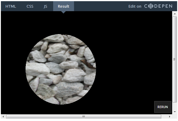
We have successfully set the parameters for the visible part of the scene. Now it would not hurt to slightly smooth the edges of this area.
Add a gradient
Instead of just cropping the visible area with black, try creating a smooth gradient. For this we need a distance that we already calculate.
Instead of returning the entire visible color of the texture, like this:
We can simply multiply the color by the distance factor:
This works because dist is the distance in pixels between the given pixel and the light source. The term of the expression (light.z * res.x) is the length of the radius. Therefore, when we look at a pixel that is just at the source of light, dist is 0. As a result, we multiply color by 1, which corresponds to the full color of the pixel.
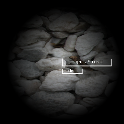
In this figure, dist is calculated for an arbitrary pixel. The value of dist varies depending on which pixel we are on, while the value of light.z * res.x is constant.
For a pixel that is on the edge of a circle, dist is equal to the radius of the circle, so we multiply color by 0, which corresponds to black color.
Step 2. Add depth
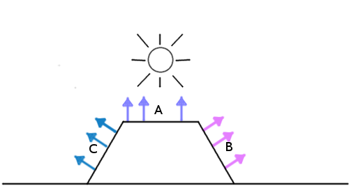
So, we have created a gradient mask for the texture. But everything still looks flat. To understand how to fix it, let's see what the lighting system is doing now and what it should do in principle.
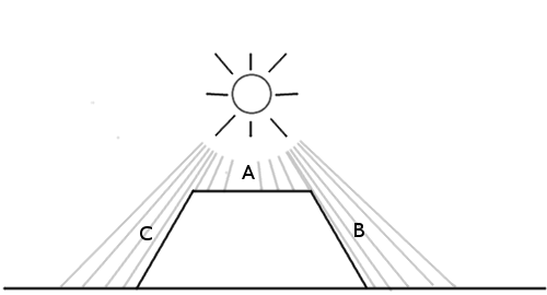
In this case, it is assumed that section A will be the most illuminated, since it is located directly under the light source, and sections B and C will be dark, because there is practically no light on them.
However, this is how the lighting system behaves now:
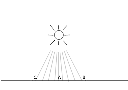
All sides are equally lit, since the only factor we take into account is the distance on the xy plane. It may seem to you that to solve a problem we just need to know the height of each of these points, but this is not quite so. Consider the following situation:
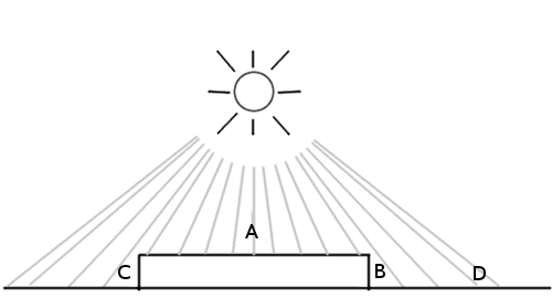
Section A is the top of the block, and B and C are its sides. D - the surface area next to the block. As we can see, sections A and D should be the lightest, but D will be slightly darker as the light falls on it at an angle. B and C, in turn, will be very dark, since the light hardly reaches them.
It turns out that you need to know rather not the height, but the direction of the front side of the surface. This is called a surface normal .
But how to transfer this data to the shader? We can send a giant array with thousands of numbers for each pixel, right? In fact, this is exactly what we are doing! Only as an array is the texture.
This is the normal map - the image, where the values of r, g, b for each pixel indicate the direction instead of color.

Above is a simple normal map. If you take the color palette, you can see that the standard “flat” direction corresponds to the color (0.5, 0.5, 1) - that is, blue, which occupies most of the image. Blue pixels look straight up. All values of r, g, b for each pixel are translated into values of x, y, z.
Take, for example, the beveled pink side. It is directed to the right, respectively, its x value, corresponding to the red color, is higher than that of the others. The same applies to other parties.
Maybe it all looks weird. But the normal map is not intended for rendering, but solely for converting normal values to the surface.
So, let's load a simple normal map:
And add it as one of the uniform variables:
To check that everything has loaded correctly, let's render the normal map instead of the texture, first modifying the GLSL code (note, while we use it as a background texture, and not as a normal map):
Step 3. Apply a lighting model
Now that we have these surface normals, we need to implement a lighting model. In other words, we need to tell the surface how to take into account all the factors available to calculate the final pixel brightness.
The simplest option would be the Phong model lighting model. Suppose there is such a surface with the given normals:
We can simply calculate the angle between the light source and the normal to the surface:
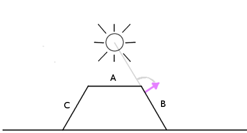
The smaller the angle, the brighter the pixel.
That is, the pixels that are directly under the light source, where the angle is zero, will be the brightest. And the darkest will be those pixels that are located on the back of the object.
Now, since we are using a simple normal map for testing, let's apply a solid color to the texture. Then we’ll see if the lighting system works.
Instead of this:
Make a solid white color (or whatever you like):
This GLSL abbreviation is needed to create vec4 with all components equal to 1.0.
Here is the algorithm of actions:
1. Get the normal vector in this pixel.
2. Get the vector of the direction of light.
3. Normalize the vectors.
4. Consider the angle between the vectors.
5. Multiply the final color by this factor.
1. Get the normal vector in this pixel.
We need to know the direction of the front side of the surface to determine how much light should fall on this pixel. This direction is stored in the normal map, so you can get the normal vector by recognizing the color of a given pixel on the normal texture.
Since the alpha value is not responsible for anything in the normal map, we need only the first 3 components.
2. Get the vector of the direction of light
Now we need to know where the light source is. Imagine it as a flashlight hanging in front of the screen where the mouse cursor is. We can determine the vector of the direction of light using the distance between the light source and the pixel:
We also need the z coordinate to determine the angle to the three-dimensional normal vector. Try changing its value, and you will see: the smaller it is, the sharper is the contrast between dark and bright areas. Think of it as the height at which you hold the flashlight above the stage: the farther it is, the more evenly the light is distributed.
3. Normalize the vectors
We use the built-in function normalize to make sure that the length of both vectors is 1.0. This is necessary because we need to calculate the angle using a dot product . If you do not quite understand how it works, it's time to improve your knowledge of linear algebra. But in this case we only need to know that the scalar product will return the cosine of the angle between two vectors of the same length.
4. Consider the angle between the vectors
For this we need the built-in dot function:
I called the variable diffuse because there is a concept of the diffuse component in the Phong light model, which is responsible for how much light hits the surface of the scene.
5. Multiply the final color by this factor.
That's all! Now just multiply the color by the coefficient. I went ahead and created a distanceFactor variable to improve the readability of the equation:
The result was a working light model! You may want to increase the radius of the light source so that the result is more visible.
Hmm, something worked wrong. It seems to have shifted the center of the light source.
Let's check the calculations again. There is a vector:
Which, as we know, will return (0, 0, 60) if the light falls directly on this pixel. After we normalize it, we get (0, 0, 1).
Remember: to get the maximum brightness, you need a normal, which points directly to the light source. The value of the normal to the surface pointing straight up is (0.5, 0.5, 1) by default.
Task: Do you see a solution to the problem? Can you fix it?
The fact is that in the color values of the texture can not be stored negative numbers. For example, you can not set the vector pointing to the left, the values (-0.5, 0, 0). Therefore, creators of normal maps should add 0.5 to each value — that is, shift the coordinate system. Keep in mind that before using the map, you must subtract this 0.5 from each pixel.
Here is the result obtained by subtracting 0.5 from the x and y values in the normal vector:
It remains to fix only one thing. Since the dot product returns the cosine of the angle, the resulting value can be from -1 to 1. But we do not need negative color values. And although WebGL automatically rejects negative values, there may still be a problem somewhere else. Let's use the built-in max function and change this:
On this:
Now you have a working lighting model!
You can bring back the texture with stones. The normal map for it is available in the repository on GitHub (or by direct link here ).
You just need to fix this link in JavaScript code:
On this:
And this line of GLSL code:
Replacing the solid white color with a texture:
Finally, here is the result:
prntscr.com/auy52h
On CodePen, you can create a source code branch and edit it.
Optimization Tips
The GPU is very effective, but it will be helpful to know what factors may hinder its operation. Here are some simple tips:
Branching
When working with shaders, it is better to avoid branching where possible. When working with code for a CPU, you rarely have to worry about a lot of if statements. But for the GPU, they can be a serious hindrance.
To understand the reason, remember again that the GLSL code is executed in parallel for each individual pixel on the screen. The operation of a video card can be significantly optimized, provided that all pixels require the same operations. If there are many if statements in the code, the optimization may decrease, since different pixels will require the execution of different code. Of course, it depends on the characteristics of those or other components, as well as on the features of using a video card. But this is useful to keep in mind to speed up the shader.
Deferred rendering
This is a very useful technique for working with lighting. Imagine if we wanted to make not 1 light source, but 2, 3 or even 10. We would have to calculate the angle between each normal to the surface and each light source. This would very quickly reduce the speed of the shader. Deferred rendering helps to correct this by dividing the work of the shader into many moves. This article addresses this issue in detail. Here I will give only a fragment on the topic of this lesson:
“Lighting is the main reason why we choose a particular development path. In the standard visualization pipeline, all calculations related to lighting should be performed on each vertex and on each fragment of the visible scene, for each light source. "
For example, instead of sending an array of points of light, you can put them on a texture as circles, where the color of each pixel will indicate the intensity of light. This way you can calculate the total effect of all the light sources in the scene and send only this final texture (or buffer, as it is also called) and calculate the lighting based on it.
Dividing a shader's work into multiple moves is a very useful technique. It is widely used to create effects of blur, water and smoke. Deferred rendering doesn’t fit in a bit with the topic of this lesson, but we’ll look at it in more detail in the next lesson!
Further steps
Now that you have a working lighting shader, you can try the following:
• Change the height (z value) of the light vector to see what effect it will have.
• Change the light intensity. This can be done by multiplying the diffuse component by the coefficient.
• Add the ambient component to the light calculation equation. This implies adding minimal (initial) lighting to the scene to create more realism. In real life, there are no absolutely dark objects, because the minimum amount of light still falls on any surface.
• Try to create one of the shaders discussed in this lesson on WebGL. They are created based on Babylon.js, not Three.js, but you can go directly to the GLSL settings. In particular, you might be interested in cel shading and Phong shading.
• Check out the interesting work on the GLSL Sandbox and ShaderToy sites.
Links
The texture with stones and the normal map used in this tutorial were taken from the OpenGameArt site. Among other things, there are many programs available for creating normal maps. If you want to learn more about how normal maps are created, see also this article.
In the first lesson of this series we covered the basics of creating graphic shaders. In the second, we studied the general algorithm of actions when setting up shaders for any platform. Now it's time to understand the basic concepts from the field of graphic shaders without reference to the platform. For convenience, we will still use JavaScript / WebGL in the examples.
Before moving forward, make sure that you choose the most convenient way to work with shaders. The easiest option would be javascript / webgl, but I recommend trying your hand at your favorite platform.
')
Goals
By the end of this lesson you will not only be able to boast a deep understanding of the principle of operation of lighting systems, but also create such a system yourself from beginning to end.
This is what the final result will look like ( go to CodePen to switch the lighting):
Despite the fact that ready-made lighting systems are built into many game engines, understanding their creation will help you apply more flexible settings and make your game more unique. The role of shader effects should not be reduced to a purely decorative: they can be used to create new game mechanics.
An excellent example of dynamic lighting is the Chroma game:
Getting Started: starting scene
We will skip most of the preparations, since all of this was covered in the previous lesson. Let's start with a simple fragmentary shader with a texture:
So far, nothing special. JavaScript code sets the scene settings and sends the texture to the render, and the screen settings to the shader.
var uniforms = { tex : {type:'t',value:texture},//The texture res : {type: 'v2',value:new THREE.Vector2(window.innerWidth,window.innerHeight)}//Keeps the resolution } Declare variables in GLSL code:
uniform sampler2D tex; uniform vec2 res; void main() { vec2 pixel = gl_FragCoord.xy / res.xy; vec4 color = texture2D(tex,pixel); gl_FragColor = color; } It is necessary to adjust the coordinates of the pixels before using them to draw textures.
But first, let's do the following task to warm up.
Task: Will you manage to display the texture, keeping its proportions? Try to do it yourself before proceeding to the solution below.
The reason why the texture is stretched is quite obvious. But here's a little hint: take a look at the line in which the coordinates are adjusted:
vec2 pixel = gl_FragCoord.xy / res.xy; We divide vec2 by vec2, which is similar to dividing each component separately. In other words, the line above is equivalent to the following:
vec2 pixel = vec2(0.0,0.0); pixel.x = gl_FragCoord.x / res.x; pixel.y = gl_FragCoord.y / res.y; As we divide x and y into different numbers (width and height of the screen), naturally, the texture stretches.
But what would happen if we simply divided x and y from the variable gl_FragCoord by the value of x res? Or, on the contrary, the value of y res?
For simplicity, the experiment will leave everything as is until the end of the lesson. But, anyway, it is very important to understand what is happening in the code and why.
Step 1. Add a light source
First of all, let's add a light source. The light source is nothing more than a point that we send to the shader. Create a new uniform variable for this point:
var uniforms = { //Add our light variable here light: {type:'v3', value:new THREE.Vector3()}, tex : {type:'t',value:texture},//The texture res : {type: 'v2',value:new THREE.Vector2(window.innerWidth,window.innerHeight)}//Keeps the resolution } We have created a vector with three parameters, since we will use the x and y values to indicate the position of the light source on the screen, and z as its radius.
Set the light source values in the JavaScript code:
uniforms.light.value.z = 0.2;//Our radius Set the radius to 0.2, which corresponds to 20% of the screen size. However, the units do not play a special role, the size can be set in pixels. This does not affect anything until it comes to GLSL code.
Add an event listener to the JavaScript code to locate the mouse cursor:
document.onmousemove = function(event){ //Update the light source to follow our mouse uniforms.light.value.x = event.clientX; uniforms.light.value.y = event.clientY; } Now we write the shader code to make the light source work. Let's start with a simple one: let's make sure that all the pixels within the radius of light are visible, and all the others are black.
In the GLSL code, it will look something like this:
uniform sampler2D tex; uniform vec2 res; uniform vec3 light;//Remember to declare the uniform here! void main() { vec2 pixel = gl_FragCoord.xy / res.xy; vec4 color = texture2D(tex,pixel); //Distance of the current pixel from the light position float dist = distance(gl_FragCoord.xy,light.xy); if(light.z * res.x > dist){//Check if this pixel is without the range gl_FragColor = color; } else { gl_FragColor = vec4(0.0); } } So, here is what we did:
• Declared a uniform variable for the light source.
• Used the built-in distance function to determine the distance between the light source and this pixel.
• Checked the value of the distance function (in pixels). If it is more than 20% of the screen width, we return the color of this pixel, if not, we return black.
See in action - on CodePen.
Oops! It seems that something is wrong with the logic of the movement of light.
Task: Can you fix it? I repeat: try to do it yourself before watching the answer below.
We fix the movement of light
As you remember from the first lesson, the y axis is inverted here. Perhaps you are going to do the following:
light.y = res.y - light.y; This is true from a mathematical point of view, but the shader will not compile this way. The fact is that uniform variables cannot be changed. Remember: this code is executed in parallel for each pixel. Imagine how all the processor cores simultaneously try to change a single variable. Not good!
You can fix the problem by creating a new variable, rather than trying to change this. Better yet, do it before sending it to the shader:
On CodePen, you can create a source code branch and edit it.
uniforms.light.value.y = window.innerHeight - event.clientY; We have successfully set the parameters for the visible part of the scene. Now it would not hurt to slightly smooth the edges of this area.
Add a gradient
Instead of just cropping the visible area with black, try creating a smooth gradient. For this we need a distance that we already calculate.
Instead of returning the entire visible color of the texture, like this:
gl_FragColor = color; We can simply multiply the color by the distance factor:
gl_FragColor = color * (1.0 - dist/(light.z * res.x)); This works because dist is the distance in pixels between the given pixel and the light source. The term of the expression (light.z * res.x) is the length of the radius. Therefore, when we look at a pixel that is just at the source of light, dist is 0. As a result, we multiply color by 1, which corresponds to the full color of the pixel.
In this figure, dist is calculated for an arbitrary pixel. The value of dist varies depending on which pixel we are on, while the value of light.z * res.x is constant.
For a pixel that is on the edge of a circle, dist is equal to the radius of the circle, so we multiply color by 0, which corresponds to black color.
Step 2. Add depth
So, we have created a gradient mask for the texture. But everything still looks flat. To understand how to fix it, let's see what the lighting system is doing now and what it should do in principle.
In this case, it is assumed that section A will be the most illuminated, since it is located directly under the light source, and sections B and C will be dark, because there is practically no light on them.
However, this is how the lighting system behaves now:
All sides are equally lit, since the only factor we take into account is the distance on the xy plane. It may seem to you that to solve a problem we just need to know the height of each of these points, but this is not quite so. Consider the following situation:
Section A is the top of the block, and B and C are its sides. D - the surface area next to the block. As we can see, sections A and D should be the lightest, but D will be slightly darker as the light falls on it at an angle. B and C, in turn, will be very dark, since the light hardly reaches them.
It turns out that you need to know rather not the height, but the direction of the front side of the surface. This is called a surface normal .
But how to transfer this data to the shader? We can send a giant array with thousands of numbers for each pixel, right? In fact, this is exactly what we are doing! Only as an array is the texture.
This is the normal map - the image, where the values of r, g, b for each pixel indicate the direction instead of color.
Above is a simple normal map. If you take the color palette, you can see that the standard “flat” direction corresponds to the color (0.5, 0.5, 1) - that is, blue, which occupies most of the image. Blue pixels look straight up. All values of r, g, b for each pixel are translated into values of x, y, z.
Take, for example, the beveled pink side. It is directed to the right, respectively, its x value, corresponding to the red color, is higher than that of the others. The same applies to other parties.
Maybe it all looks weird. But the normal map is not intended for rendering, but solely for converting normal values to the surface.
So, let's load a simple normal map:
var normalURL = "https://raw.githubusercontent.com/tutsplus/Beginners-Guide-to-Shaders/master/Part3/normal_maps/normal_test.jpg" var normal = THREE.ImageUtils.loadTexture(normalURL); And add it as one of the uniform variables:
var uniforms = { norm: {type:'t', value:normal}, //.. the rest of our stuff here } To check that everything has loaded correctly, let's render the normal map instead of the texture, first modifying the GLSL code (note, while we use it as a background texture, and not as a normal map):
Step 3. Apply a lighting model
Now that we have these surface normals, we need to implement a lighting model. In other words, we need to tell the surface how to take into account all the factors available to calculate the final pixel brightness.
The simplest option would be the Phong model lighting model. Suppose there is such a surface with the given normals:
We can simply calculate the angle between the light source and the normal to the surface:
The smaller the angle, the brighter the pixel.
That is, the pixels that are directly under the light source, where the angle is zero, will be the brightest. And the darkest will be those pixels that are located on the back of the object.
Now, since we are using a simple normal map for testing, let's apply a solid color to the texture. Then we’ll see if the lighting system works.
Instead of this:
vec4 color = texture2D(...); Make a solid white color (or whatever you like):
vec4 color = vec4(1.0); //solid white This GLSL abbreviation is needed to create vec4 with all components equal to 1.0.
Here is the algorithm of actions:
1. Get the normal vector in this pixel.
2. Get the vector of the direction of light.
3. Normalize the vectors.
4. Consider the angle between the vectors.
5. Multiply the final color by this factor.
1. Get the normal vector in this pixel.
We need to know the direction of the front side of the surface to determine how much light should fall on this pixel. This direction is stored in the normal map, so you can get the normal vector by recognizing the color of a given pixel on the normal texture.
vec3 NormalVector = texture2D(norm,pixel).xyz; Since the alpha value is not responsible for anything in the normal map, we need only the first 3 components.
2. Get the vector of the direction of light
Now we need to know where the light source is. Imagine it as a flashlight hanging in front of the screen where the mouse cursor is. We can determine the vector of the direction of light using the distance between the light source and the pixel:
vec3 LightVector = vec3(light.x - gl_FragCoord.x,light.y - gl_FragCoord.y,60.0); We also need the z coordinate to determine the angle to the three-dimensional normal vector. Try changing its value, and you will see: the smaller it is, the sharper is the contrast between dark and bright areas. Think of it as the height at which you hold the flashlight above the stage: the farther it is, the more evenly the light is distributed.
3. Normalize the vectors
NormalVector = normalize(NormalVector); LightVector = normalize(LightVector); We use the built-in function normalize to make sure that the length of both vectors is 1.0. This is necessary because we need to calculate the angle using a dot product . If you do not quite understand how it works, it's time to improve your knowledge of linear algebra. But in this case we only need to know that the scalar product will return the cosine of the angle between two vectors of the same length.
4. Consider the angle between the vectors
For this we need the built-in dot function:
float diffuse = dot( NormalVector, LightVector ); I called the variable diffuse because there is a concept of the diffuse component in the Phong light model, which is responsible for how much light hits the surface of the scene.
5. Multiply the final color by this factor.
That's all! Now just multiply the color by the coefficient. I went ahead and created a distanceFactor variable to improve the readability of the equation:
float distanceFactor = (1.0 - dist/(light.z * res.x)); gl_FragColor = color * diffuse * distanceFactor; The result was a working light model! You may want to increase the radius of the light source so that the result is more visible.
Hmm, something worked wrong. It seems to have shifted the center of the light source.
Let's check the calculations again. There is a vector:
vec3 LightVector = vec3(light.x - gl_FragCoord.x,light.y - gl_FragCoord.y,60.0); Which, as we know, will return (0, 0, 60) if the light falls directly on this pixel. After we normalize it, we get (0, 0, 1).
Remember: to get the maximum brightness, you need a normal, which points directly to the light source. The value of the normal to the surface pointing straight up is (0.5, 0.5, 1) by default.
Task: Do you see a solution to the problem? Can you fix it?
The fact is that in the color values of the texture can not be stored negative numbers. For example, you can not set the vector pointing to the left, the values (-0.5, 0, 0). Therefore, creators of normal maps should add 0.5 to each value — that is, shift the coordinate system. Keep in mind that before using the map, you must subtract this 0.5 from each pixel.
Here is the result obtained by subtracting 0.5 from the x and y values in the normal vector:
It remains to fix only one thing. Since the dot product returns the cosine of the angle, the resulting value can be from -1 to 1. But we do not need negative color values. And although WebGL automatically rejects negative values, there may still be a problem somewhere else. Let's use the built-in max function and change this:
float diffuse = dot( NormalVector, LightVector ); On this:
float diffuse = max(dot( NormalVector, LightVector ),0.0); Now you have a working lighting model!
You can bring back the texture with stones. The normal map for it is available in the repository on GitHub (or by direct link here ).
You just need to fix this link in JavaScript code:
var normalURL = "https://raw.githubusercontent.com/tutsplus/Beginners-Guide-to-Shaders/master/Part3/normal_maps/normal_test.jpg" On this:
var normalURL = "https://raw.githubusercontent.com/tutsplus/Beginners-Guide-to-Shaders/master/Part3/normal_maps/blocks_normal.JPG" And this line of GLSL code:
vec4 color = vec4(1.0);//solid white Replacing the solid white color with a texture:
vec4 color = texture2D(tex,pixel); Finally, here is the result:
prntscr.com/auy52h
On CodePen, you can create a source code branch and edit it.
Optimization Tips
The GPU is very effective, but it will be helpful to know what factors may hinder its operation. Here are some simple tips:
Branching
When working with shaders, it is better to avoid branching where possible. When working with code for a CPU, you rarely have to worry about a lot of if statements. But for the GPU, they can be a serious hindrance.
To understand the reason, remember again that the GLSL code is executed in parallel for each individual pixel on the screen. The operation of a video card can be significantly optimized, provided that all pixels require the same operations. If there are many if statements in the code, the optimization may decrease, since different pixels will require the execution of different code. Of course, it depends on the characteristics of those or other components, as well as on the features of using a video card. But this is useful to keep in mind to speed up the shader.
Deferred rendering
This is a very useful technique for working with lighting. Imagine if we wanted to make not 1 light source, but 2, 3 or even 10. We would have to calculate the angle between each normal to the surface and each light source. This would very quickly reduce the speed of the shader. Deferred rendering helps to correct this by dividing the work of the shader into many moves. This article addresses this issue in detail. Here I will give only a fragment on the topic of this lesson:
“Lighting is the main reason why we choose a particular development path. In the standard visualization pipeline, all calculations related to lighting should be performed on each vertex and on each fragment of the visible scene, for each light source. "
For example, instead of sending an array of points of light, you can put them on a texture as circles, where the color of each pixel will indicate the intensity of light. This way you can calculate the total effect of all the light sources in the scene and send only this final texture (or buffer, as it is also called) and calculate the lighting based on it.
Dividing a shader's work into multiple moves is a very useful technique. It is widely used to create effects of blur, water and smoke. Deferred rendering doesn’t fit in a bit with the topic of this lesson, but we’ll look at it in more detail in the next lesson!
Further steps
Now that you have a working lighting shader, you can try the following:
• Change the height (z value) of the light vector to see what effect it will have.
• Change the light intensity. This can be done by multiplying the diffuse component by the coefficient.
• Add the ambient component to the light calculation equation. This implies adding minimal (initial) lighting to the scene to create more realism. In real life, there are no absolutely dark objects, because the minimum amount of light still falls on any surface.
• Try to create one of the shaders discussed in this lesson on WebGL. They are created based on Babylon.js, not Three.js, but you can go directly to the GLSL settings. In particular, you might be interested in cel shading and Phong shading.
• Check out the interesting work on the GLSL Sandbox and ShaderToy sites.
Links
The texture with stones and the normal map used in this tutorial were taken from the OpenGameArt site. Among other things, there are many programs available for creating normal maps. If you want to learn more about how normal maps are created, see also this article.
Source: https://habr.com/ru/post/282131/
All Articles