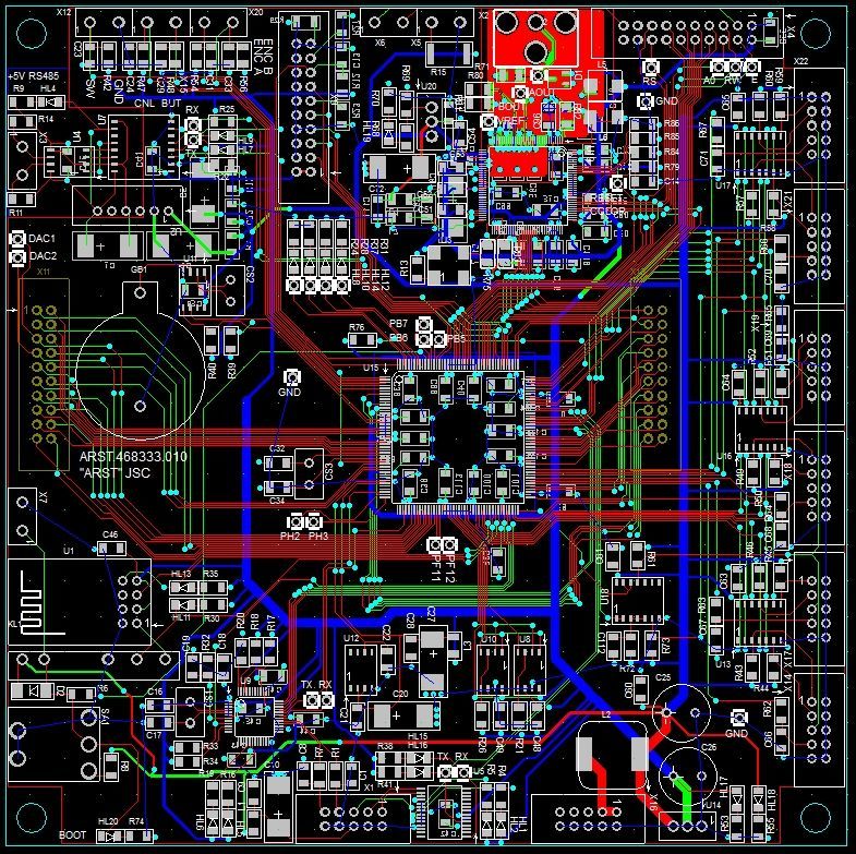
Controller board based on STM32F7 with video output
By the nature of their work, it is often necessary to design various types of control and measurement systems. Of course, based on microcontrollers. First they used AVR, then the next ATxMega family, finally settled on the STM32 family. Despite the different functionalities of the designed devices, the mass of functions remains unchanged: an interface with the user and external devices, data storage, a real-time clock, etc. Therefore, the idea was to make a universal controller board containing the main nodes, and additional plug-in cards will extend the functionality to the required . At first it was a controller on STM32F103, then on 207, then on 429. And now on the 746 chip.
But the main novelty on this board is the video output. Prior to this, as a rule, a graphic display was used (monochrome, 320 x 240). But this approach has its drawbacks:
1. When switching to a decent-sized color display> 5 "with a built-in controller, the price becomes large enough.
2. You have to use only one type of display, since the interfaces are usually incompatible.
')
But then the thought came to use standard car monitors, the price of which is quite democratic, there are a large number of manufacturers and there are different sizes.
For this, I had to implement a video output.
After searching the Internet, the graphics controller S1D13746F01 was found, which has a built-in 321 kB memory and composite video output. Of course, there is S-Video, but it was not planned to be used. It was also detected and datasheet on the Evaluation Board with a detailed wiring diagram, but on the case, which has 100 conclusions.
After reading the datasheet on the microcircuit, we discovered a certain feature of the organization of access to the internal memory, namely the impossibility of recording at certain addresses. That is, the video buffer must be rewritten all. This feature makes it necessary to organize the storage of the video buffer in the memory of the microcontroller and to rewrite it with the necessary frequency.
To organize the video buffer you need 320 * 240 = 76800 bytes. The number of colors in this case will be equal to 256. This color encoding format is indicated in the video controller documentation as RGB 3: 3: 2. That is, 3 bits for red, 3 bits for green and 2 bits for blue. Total 8 red flowers of different levels, 8 green and 4 blue.
Video chip recording is carried out programmatically through the port. Here is the C program.
The recording time of the entire video buffer is approximately 20 ms. If desired, you can output video 50 frames / sec, but the controller will only deal with the output. :) In real-life tasks, it is necessary to rewrite the screen from 3 to 10 times per second.
And here's a picture on a connected car monitor, bought at a nearby store. Monitor size - 7 ".
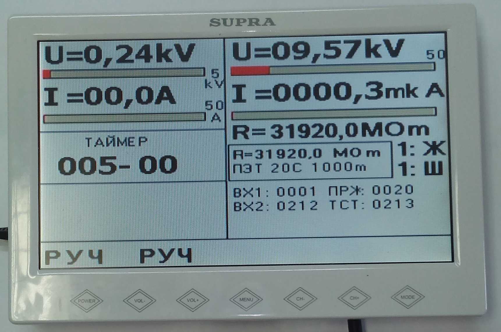
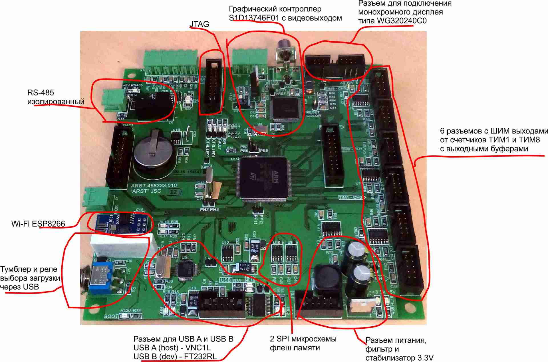
This is a high voltage test device control. In addition to the video output on the controller board, there is also a connector for connecting a Winstar monochrome display WG320240C0.
Brief description of the main components on the controller board:
Here is a controller turned out.
But the main novelty on this board is the video output. Prior to this, as a rule, a graphic display was used (monochrome, 320 x 240). But this approach has its drawbacks:
1. When switching to a decent-sized color display> 5 "with a built-in controller, the price becomes large enough.
2. You have to use only one type of display, since the interfaces are usually incompatible.
')
But then the thought came to use standard car monitors, the price of which is quite democratic, there are a large number of manufacturers and there are different sizes.
For this, I had to implement a video output.
After searching the Internet, the graphics controller S1D13746F01 was found, which has a built-in 321 kB memory and composite video output. Of course, there is S-Video, but it was not planned to be used. It was also detected and datasheet on the Evaluation Board with a detailed wiring diagram, but on the case, which has 100 conclusions.
After reading the datasheet on the microcircuit, we discovered a certain feature of the organization of access to the internal memory, namely the impossibility of recording at certain addresses. That is, the video buffer must be rewritten all. This feature makes it necessary to organize the storage of the video buffer in the memory of the microcontroller and to rewrite it with the necessary frequency.
To organize the video buffer you need 320 * 240 = 76800 bytes. The number of colors in this case will be equal to 256. This color encoding format is indicated in the video controller documentation as RGB 3: 3: 2. That is, 3 bits for red, 3 bits for green and 2 bits for blue. Total 8 red flowers of different levels, 8 green and 4 blue.
Video chip recording is carried out programmatically through the port. Here is the C program.
void refresh_display(void) { unsigned long h, s; unsigned short out_port; for (s = 0; s < Height_window; s++) // { for (h= 0; h < Width_window; h++) // { out_port = gLCD_port->ODR; out_port &= 0xFF00; out_port |= video_buffer[h] [s]; // gLCD_port->ODR = out_port; gLCD_color_WE_low; // gLCD_color_WE_high; } } } The recording time of the entire video buffer is approximately 20 ms. If desired, you can output video 50 frames / sec, but the controller will only deal with the output. :) In real-life tasks, it is necessary to rewrite the screen from 3 to 10 times per second.
And here's a picture on a connected car monitor, bought at a nearby store. Monitor size - 7 ".
This is a high voltage test device control. In addition to the video output on the controller board, there is also a connector for connecting a Winstar monochrome display WG320240C0.
Brief description of the main components on the controller board:
- 6 connectors with complementary PWM outputs for controlling half bridges
- USB Host is implemented on the VNC1L microcircuit, mainly used to record information on flash drives.
- USB Device - FT232RL microcircuit, used to program the microcontroller from a computer via USB
- isolated RS485 for communication with MODBUS devices
- Wi-Fi based on the ESP8266 module
- RTC - DS1307 with a lithium battery, connected via I2C
- 2 flash memory chips, one used to store the device configuration, the other for archive data
- ION based on REF192
- 2 expansion pin 20 pin each, one for analog signals, the other for digital.
Here is a controller turned out.
Source: https://habr.com/ru/post/281451/
All Articles