ZigBee wireless networks. Part 1 [introductory]
Introduction
 Now the concept of IoT ("Internet of Things") is spoken everywhere. A “smart” home appliance appears that can connect to the network (Bluetooth / Wi-Fi) wirelessly and start sending out notifications that the washing / cooking / boiling water task has been completed and it would be nice to do something about it. Most of these “smart” devices are powered directly from the mains. But what if you want to receive information from a wireless thermometer and at the same time do not change the battery every week? Or have a wireless switch with a small battery for which you do not need to make walls? And it would be good to combine such devices into a single distributed network that can be controlled remotely and which itself, based on the readings of the sensors / detectors / counters, could make some decisions.
Especially for solving such problems, ZigBee wireless technology was created, about which we will begin the conversation.
Wireless networking technology
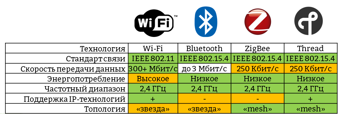
There are a large number of wireless technologies, each of which has its own characteristics. The table below describes the wireless communication protocols for the 2.4 GHz frequency.
Comparative table of popular wireless technologies
- Wi-Fi technology
Wi-Fi technology was created as a replacement for the wired Ethernet interface. Therefore, this technology offers high data transfer speeds, but does not allow to develop nodes operating for a long time from low-capacity power sources due to high power consumption. - Bluetooth technology
Bluetooth technology with the advent of the standard 4.0 (Bluetooth Smart or Bluetooth Low Energy) has become much more attractive for developers of wearable electronics, as power consumption has decreased several times in comparison with previous versions [ 1 ]. But if the task is to build a wireless low-power system that will cover several rooms or even buildings, this technology will not work, as only the star network is supported. The same is true for Wi-Fi. - ZigBee and Thread technology
ZigBee and Thread technologies were originally developed to create reliable distributed networks of sensors and control devices with low data transfer rates. These technologies support network mesh topology, sleeping and mobile nodes, as well as nodes that support the operation of the relay and self-healing algorithms. The table shows the speed of 250 kbps - this is the maximum network bandwidth. Useful speed will be about 30-40 kbps within neighboring nodes and 5-25 kbps when using retransmission. The main difference between Thread technology and ZigBee is that it adds support for the IP protocol, which simplifies the integration of Thread networks with network applications. We will talk about the features of Thread technology another time.
Comparison of network topologies
About the supported network topologies in the previous chapter it was said, but it was not said about features. Consider this example:
"Star" vs. "Mesh"
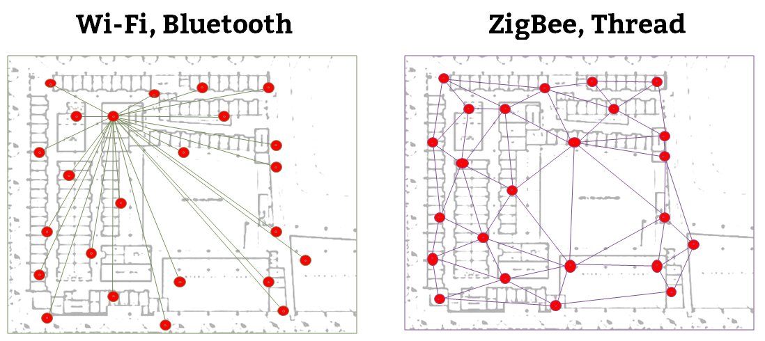
In Bluetooth and Wi-Fi networks, network interaction goes through a central gateway. And if it fails, the exchange of data will become impossible.
In addition, individual nodes may be left without communication if an obstacle on the way of a radio signal unexpectedly arises.
')
In ZigBee and Thread networks, communication reliability is enhanced by the presence of redundant connections between devices. All devices that do not go to sleep mode act as routers that are responsible for routing network traffic, choosing the optimal route and relaying packets. Even if the device that acted as the network organizer fails, the ZigBee network will continue to function further. The occurrence of interference or obstacles, as well as the failure of any of the routers, is not critical due to the presence of redundant links. Therefore, with the introduction of additional nodes that are stationary powered and can perform the tasks of the router, the network becomes more reliable.
Typical ZigBee Network Structure
Now we’ll focus on the structure of the ZigBee network itself and the types of devices it may have.
Typical ZigBee Network Structure
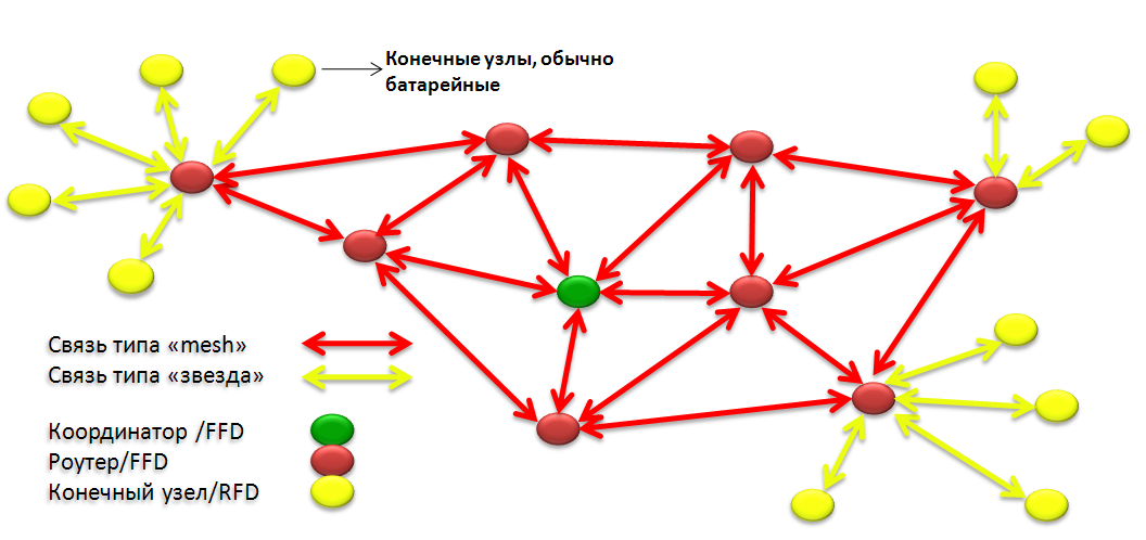
The coordinator is the node that organized the network. It is he who chooses the security policy of the network, allows or denies new devices to connect to the network, and also, in the presence of interference on the radio, initiates the process of transferring all devices on the network to another frequency channel.
A router is a node that has a stationary power and therefore can constantly participate in the network. The coordinator is also a router. On nodes of this type is responsible for routing network traffic. Routers constantly maintain special routing tables, which are used for laying the optimal route and searching for a new one if any device suddenly fails. For example, routers on a ZigBee network can be smart sockets, lighting control units, or any other device that has a power connection.
The end device is a device that connects to the network through a parent node — a router or coordinator — and does not participate in traffic routing. All communication with the network for them is limited to transferring packets to the "parent" node or reading the incoming data from it. The “parent” for such devices can be any router or coordinator. The final devices most of the time are in sleep mode and send a control or informational message usually only on a specific event (pressing the switch button, opening a window or door). It allows them to save energy of the built-in power supply for a long time. An example of end devices in ZigBee networks may be wireless switches that control the operation of luminaires and operate on batteries, water leakage sensors, and door opening / closing sensors. It should be said that the final devices are divided into 3 categories, each of which has its own characteristics, but about them in the next part.
Since the end devices are in sleep mode most of the time and wake up only to poll the parent node for messages for themselves or for data transmission, this allows the battery power supply to be economized. Experienced measurements of energy consumption for a sleeping end device based on the ETRX357 module, which will be discussed later in various operating modes:
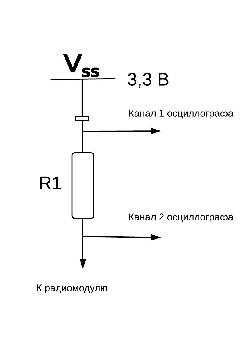
Power was supplied to the module through a resistor R1 with a rating of 10 ohms. Two oscilloscope probes were connected before and after the resistor. After that, using the subtraction function on the oscilloscope, the voltage drop across the resistor was recorded. After that, using Ohm's law  , it is possible to calculate the current consumption. In addition, since the time in the active mode is fixed, you can find the charge, and then the power expended in joules.
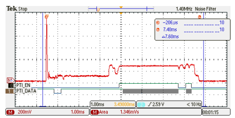
The transmission cycle takes 7.5 ms, the energy consumed at 3.3 V supply voltage is 444.2 mJ.
A typical alkaline battery has a power margin of ~ 10.8 kJ. This energy is enough to send 24 million such requests. If the sleeping node sends this message every 10 seconds, it will be 8640 requests per day. That is, theoretically, if you do not take into account the aging of the battery, its energy will be enough for ~ 2700 days = 7 years.
In this mode, the sleeping device polls its parent node for the presence of an incoming message. If not, then the sleeping node goes into power saving mode.

The transmission cycle takes 3.2 ms, the energy consumed at a 3.3 V supply voltage is 184 μJ.
A typical alkaline battery has a power margin of ~ 10.8 kJ. This energy is enough to send 60 million such requests. If the sleeping node sends such a request once every 10 seconds, it will be 8640 requests per day. That is, theoretically, if you do not take into account the aging of the battery, its energy will be enough for ~ 6940 days = 19 years.
Development of standard ZigBee devices
“Great,” the reader will think. - another proprietary protocol with support for mesh-topology. This is no surprise. ” However, the ZigBee alliance for all those years that ZigBee technology existed, carried out a great deal of work on the standardization of not only the network layer, but also the application layer of the devices being developed [ 2 ]. There is a large library of ZigBee clusters (ZCL), which describes over 200 devices, such as switches, lighting control units, an interface for connecting sensors, counters, and more [ 3 ]. And for some types of systems (home automation systems, meter reading systems, etc.), special profiles have been developed, which include a whole set of standard devices. They allow wireless nodes from different manufacturers to understand each other at the application level. The standard profile describes the standard commands and behaviors of a particular device, for example, the climate control system control unit or the lamp control unit.
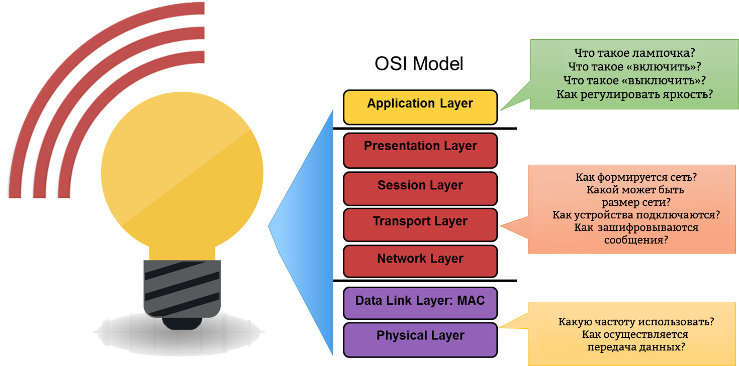
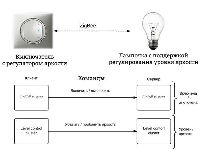
An example of how a lighting control system can be implemented using a standard cluster library. We will analyze the details another time, but for now it’s enough to understand the following:
- the light bulb has a set of stored attributes (state - on / off; brightness level)
- the switch can send commands to change the available light bulb attributes
- when receiving the command, the light takes the specified state
The cluster library indicates which attributes and commands are mandatory for certain devices and which are optional. This allows you to implement a standard interface interaction between ZigBee-devices.
Where to begin?
Radio module
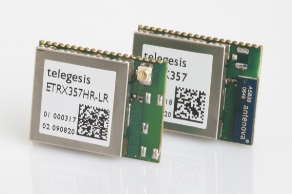 For a quick start, when there is no desire or opportunity to deal with the ZigBee software stack, you should pay attention to the ETRX357 modules. All modules have built-in firmware from the manufacturer, which allows you to work with analog and digital peripherals, as well as with network functions, using a set of AT-commands. To start working with the radio module, it is enough to connect the power lines and the TxD and RxD lines of the UART serial interface.
| Team | Description |
|---|---|
| AT + PANSCAN | Running a scan for ZigBee networks |
| AT + EN | Create network |
| AT + JN | Join network |
| AT + DASSL | Leave network |
| AT + DASSR | Request to remote host to exit the network |
| ATSXX? | Reading the contents of the SXX register |
The standard firmware also includes a number of functions that can be triggered by an interrupt from an I / O port, a timer / counter, or upon certain events, such as connecting to a network or initializing a radio module. Example of available functions:
- I / O port state switching
- Sending information to the data collection unit on the status of 16 digital outputs of the radio module, digitized data from the connected sensors and information about the level of supply voltage
- Switch to active mode or power saving mode
- Opening a “transparent channel” with another device on the network
A few words about the "transparent channel". When switching to this mode, all information arriving via the UART interface to the radio module is transmitted to the UART interface of another radio module. This channel is bidirectional, and also inherits the advantages of the ZigBee technology - if there are routers in the network, there will be no data loss in such a communication channel since all “transparent channel” packets will be automatically retransmitted if necessary. Due to this, it is possible to organize a communication channel with a maximum range of several kilometers.
Software implementation of the ZigBee stack
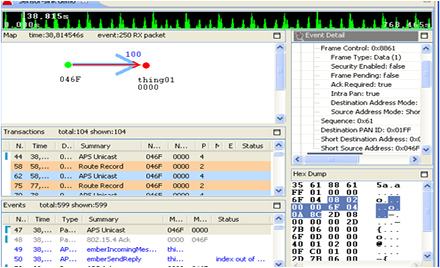
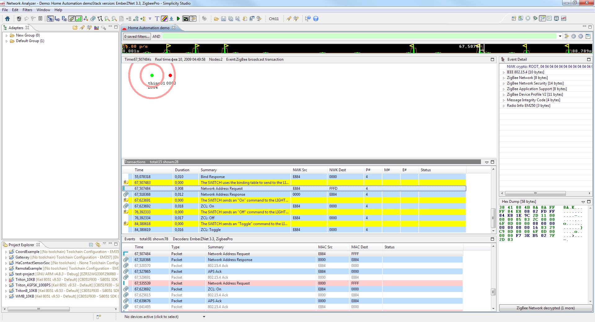
If the standard features of the firmware are not enough, then you can use the implementation of the software stack ZigBee from the company Silicon Labs - Ember ZNet PRO. Since the modules are based on the EM357 chip, the transition from standard firmware to developing your own application will require only acquiring the ISA3 debugger with which you can do both in-circuit debugging of the device and debugging the application at the network level.
The figure on the right shows an example of how data about a package’s route and its decryption are displayed.
To simplify the process of creating an application, an application builder is provided, which, for the selected ZigBee device configuration, generates an application framework and creates functions in which the developer must add the required application logic.
All utilities are included in the software package Simplicity Studio , which also includes a demo version of the Ember ZNet PRO stack. Therefore, you can right now download and see how it works.
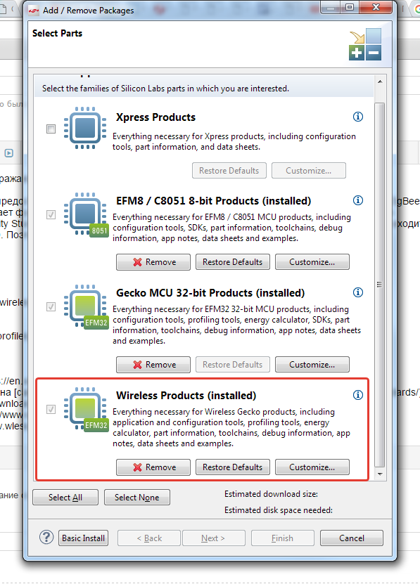
After you download and install Simplicity Studio, check if the Wireless extension is installed.

We are interested in the Wireless Products package.
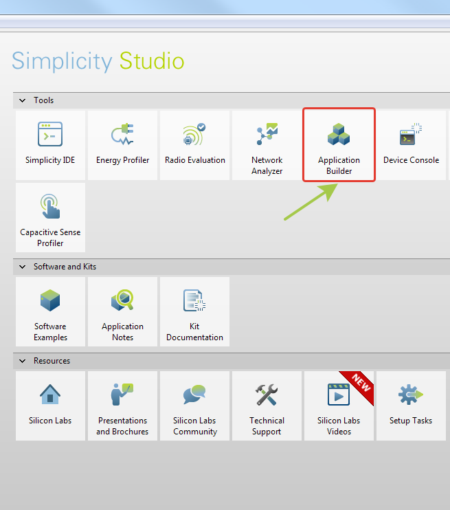
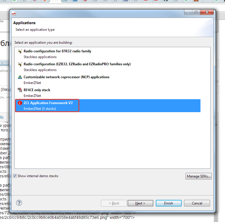
Select Application Builder Utility
Next, select the framework. For ZigBee applications, this will be the ZCL Application Framework v2. Important: you need to check the box to display the demo built-in stacks.
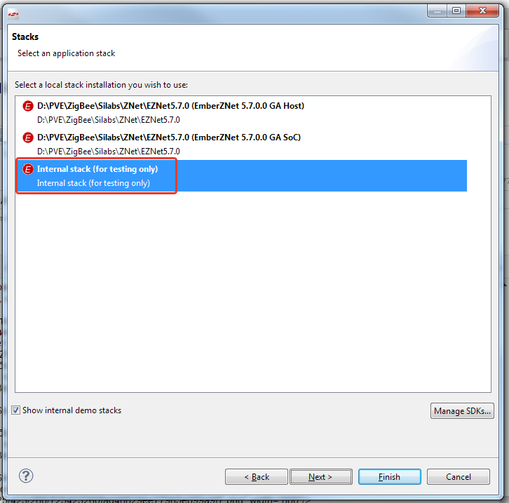
Choose the Internal Stack
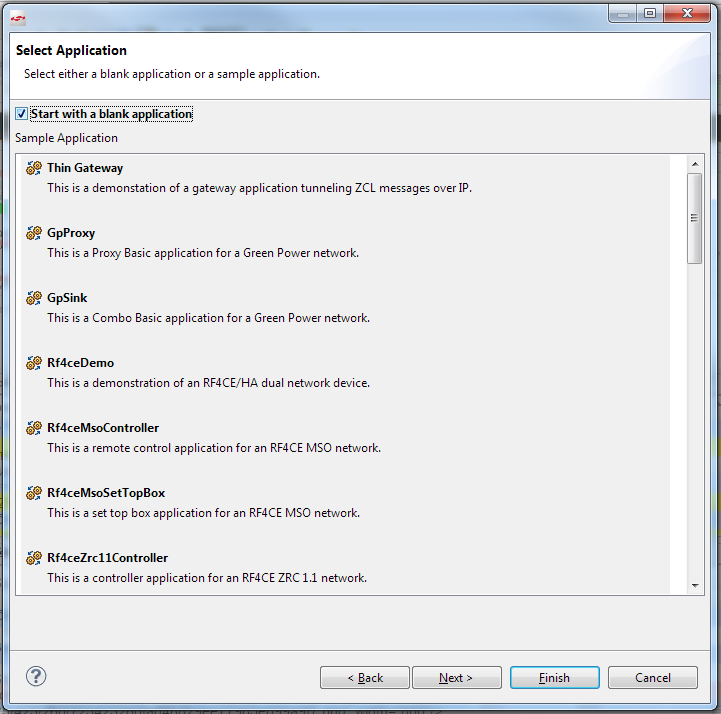
After that, you can start working with either an empty application, or choose from a list of ready applications and study its structure.
After you download and install Simplicity Studio, check if the Wireless extension is installed.
We are interested in the Wireless Products package.
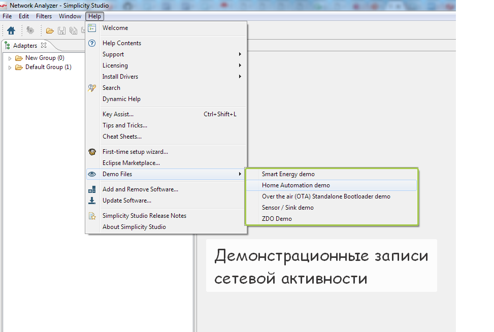
After that, you can go to the Network Analyzer utility and select any available demonstration record of network activity.

Result
Conclusion
I hope that this article has helped to understand the main features of ZigBee wireless technology and you can figure out in which applications you can use it. The technology itself is fully open and all its specifications are available for download from the ZigBee alliance website. And the standard cluster library is a real language of interaction between devices that surround us every day: home automation devices, security systems, sensor equipment and much more.
If you have any questions, send them to me by mail or write in the comments.
PS For those who could not master the text, there is an opportunity to watch introductory videos using ZigBee technology .
- Wikipedia article - Bluetooth Low Energy
- Description of application level standardization on the ZigBee Alliance website
- ZigBee Cluster Library
- Technical description of the module ETRX357
- List of AT commands of the ETRX357 module
List of articles
Source: https://habr.com/ru/post/281048/
All Articles