As I wrote the library under IEC 870-5-104 on Arduino using Wireshark
In this article, I would like to talk about my acquaintance with the IEC 870-5-104 data transfer channel from a controlled (slave) device by writing a simple Arduino library.
IEC 60870-5-104 is a telemechanical protocol designed to transmit TM signals to an automated process management system that regulates the use of network access using the TCP / IP protocol. It is most often used in power engineering for information exchange between power systems, as well as for receiving data from measuring transducers (voltmeters, electricity meters, etc.).
Stack Protocol IEC 670-5-104:
')
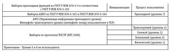

APCI - Application Level Control Information can be used as a separate control frame (U frame or S frame).
ASDU - Application-level data blocks, consists of a data block identifier and one or more information objects, each of which includes one or more homogeneous information elements (or combinations of information elements).
APDU - Application layer protocol data unit.
TC - TV alarm.
TI - telemetry.
TU - remote control.
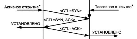
The master station initiates the establishment of a TCP connection by sending a TCP packet with a flag (SYS). A connection is considered established if, during the monitoring time (t0), the monitored station (slave) has issued a “active open” (SYS ACK) to its TCP / IP level. The watchdog time t0 is called “Connection setup timeout”. The timer t0 determines when the opening is canceled and does not determine the beginning of a new connection attempt.
The interaction with the transport layer is performed by the standard library for Arduino Ethernet.h boards. That is, the first step is to establish a TCP / IP connection between the monitored and the monitoring stations. To do this, you need to initialize the device in the Arduino sketch and create a server that will wait for incoming connections through the specified port.
If you download this sketch, the following will happen:

Establishing a connection, then comes the STARTDT act package unknown for Arduino and after a certain time the connection is broken. Next, you need to understand what a STARTDT act.
In IEC 670-5-104, there are 3 types of format for transmission:
After a successful “triple handshake”, the controlling (master) station sends an APDU STARTDT (data transfer start). STARTDT initiates for the controlled (Slave) station the resolution of the transmission of ASDUs (frames I) in the direction of the controlling (master), to continue the work, you must confirm STARTDT, if the controlled (Slave) station is ready to transmit data blocks. If the monitored (slave) station does not confirm the execution of STARTDT, then the controlling (master) station causes the mandatory closure of the IP connection.
Thus, further it is necessary to count the bytes received from the controlling (master) station and disassemble them.
After reading the data you need to parse them and form the answer.
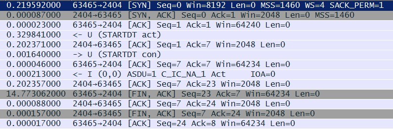
Here's what the package containing the STARTDT block in the Wireshark program looks like, the APDU is a U-format block that consists only of APCI.
APCI - Application Level Control Information can be used as a separate control frame (U frame or S frame).

In short, we can say that the APCI block determines the type of APDU block and its length. APCI consists of the following six bytes:
1. Sign of initialization of the variable-length APDU block, starting with START2 68h;
2. The length of the APDU, in this example is four bytes;
3. The control byte in which the type of APDU is determined, in this example, a value of seven is written, which means a request for data transfer;
4,5,6 Not used.

Based on the above, before answering, it would not hurt to determine what type of APDU the monitoring station sent us. Knowing that the type of APDU is written in the third order of reading the APCI block byte, I will save it in an integer variable.
Note: If an “I” format packet is received, then 3 bytes in APCI will also contain the low word value of the received packets counter,

therefore, we had to slightly complicate the construction of the definition of the type APDU.
It can be seen from the figure above that the type of APDU corresponding to the value 7 is STARTDT act, respectively, it is necessary to respond with the same package structure, only the type value should have the value 11 (0b), which corresponds to STARTDT con.
After updating the sketch, we observe the following order of exchange:
Establishing a connection, a request for data transfer, confirmation of the request and another new yet unknown APDU of format I type 1 C_IC_NA Act.
The APDU <100> C_IC_NA_1, in addition to the APCI block, also has an ASDU (Application Level Data Block), which together form the APDU Protocol Data Block of the Application Layer.

Consider in more detail the received APDU.
APCI:
ASDU:
In response to <100> C_IC_NA_1, it is necessary to respond with a confirmation of the request, transfer the process information objects stored at the monitored station and complete the activation.
To send an acknowledgment, it is necessary in ASDU <100> C_IC_NA_1 to write to byte a value indicating the cause of transmission (CauseTX) equal to 7, to send the activation end to send the reason of transmission (CauseTX) equal to 10 to send the activation completion request.
After updating the sketch, we observe the following order of exchange:
Establish a connection, request for data transmission, confirmation, request for a general interrogation of a station from a monitoring station, completion of initialization, request for a general interrogation of a station to the direction of a controlled station, confirmation of a general interrogation, forwarding the values of all available signals at the monitoring station, completion of a general interrogation and unknown APCI format S.
The station inquiry request is issued in the direction of the monitored station:
- if “END OF INITIALIZATION” is received from the controlled station or
- if the central station detects a loss of the channel (unsuccessful repeated request of the data link layer) and its subsequent recovery.
An APDU S format block consisting only of APCI is intended to confirm the received APDU I format. For S-format 7, the upper bits of the service field of byte 1 and byte 2 are not involved, and byte 3 (7 high bits) and byte 4 determine the current number of the received parcel.
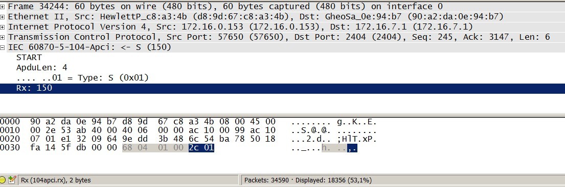
In this case, the S block indicates that the controlling (master) station is ready to receive data within a certain time, not exceeding, the timeout t3 determined on the side of the controlling (master) station. That is, the master station tells us "I am ready to receive data!". Next, you need to take care of what data to transfer and where to get it.
What can be transmitted? There are several types of information defined in IEC 870-5- 104:
In this example, the transfer of control information is considered using examples 1, 11 and 13 of functions (single-element, measurement scalable, measurement short format with a floating point). Data is generated randomly. It is also necessary to take into account that each transmitted signal has a quality byte.

A simple algorithm for determining the quality of the signal:
It is also necessary to take into account that for each signal there is a unique identifier IOA, in the power industry it is customary to allocate these addresses as follows:
To transfer the values of signals to an array for sending, use the EEPROM library:
And so having received the APDU confirmation S or I format from the monitoring station, you can begin to transmit the available data, not forgetting to increase the number of the transmitted frame.
After uploading the sketch to Wireshark, we observe that data transfer has finally begun.

Next, I provide a description of the structure of the ASDU <100> M_SP_NA_1 single-element indication.
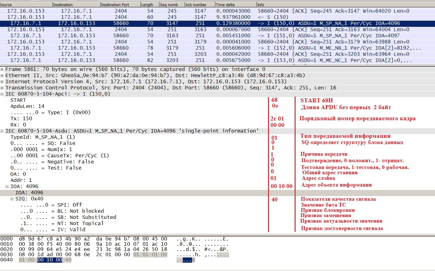
TypeId is a type of information.
SQ - variable structure classifier.
Two structures of data blocks are provided for:
1. A block containing i information objects, each of which contains one information item (or one combination of elements); the high-order bit of the classifier for the variable structure SQ (single / sequence) is 0, the remaining 7 bits specify the number i.
2. A block containing a single information object that contains j elements or the same combinations of information elements; the most significant bit (27 = 80h) of the SQ classifier is 1, the remaining 7 bits specify the number j.
CauseTx - the reason for the transfer.
Addr - slave address (specified when configuring the wizard).
IOA is the address of the information object; at this address, the monitoring station will link its
SIQ tag — the quality indicator of the transmitted signal.
The ASDU structure of the function block <11> M_ME_NB_1 :
In response to the received data, the master will send blocks of format S and the process will loop until the monitored (slave) device stops transmitting frames.
Testing procedures are used to monitor the performance of transport connections. The procedure is performed independently of the “activity” of the IP connection, if during the control time t3 no frames were received (I, U, S). Time t3 is subject to negotiation and is called “Time out for sending test blocks in case of long idle time”. The test procedure is implemented by sending a test APDU (TESTFR = act), which is confirmed by the received station using the APDU (TESTFR = con).
If the control station (master) receives an APDU whose value in the byte responsible for the type of APDU is sixty network (TESTFR), it means that during the time t3, no frame was received from the monitored station (I, U, S) , and if during the time t1 does not respond with a confirmation, the connection will be terminated.
That's all, if anyone is interested, then in the next article I will look at the IEC 670-5-104 protocol from the controlling (master) station using the example of Arduino.
What is IEC 870-5-104 and where does it apply?
IEC 60870-5-104 is a telemechanical protocol designed to transmit TM signals to an automated process management system that regulates the use of network access using the TCP / IP protocol. It is most often used in power engineering for information exchange between power systems, as well as for receiving data from measuring transducers (voltmeters, electricity meters, etc.).
Stack Protocol IEC 670-5-104:
')
Materials used
- Arduino UNO board;
- Ethernet shield (HR911105a);
- ABB MicroScada will play the role of IEC 60870-5-104;
- Wireshark to analyze traffic.
Brief description of the stages of work
- Installing TCP / IP connection on port 2404;
- Confirmation of the request for data transfer (STARTDT act / con);
- Request for a general station survey;
- Preparation and transmission of data to the controlling (master) station;
- Testing procedures.
Training
- Arduino board connected to PC;
- Configured as appropriate network interface;
- A master station was set up (104 lines added and a controlled (slave) device added).
Terms and abbreviations
APCI - Application Level Control Information can be used as a separate control frame (U frame or S frame).
ASDU - Application-level data blocks, consists of a data block identifier and one or more information objects, each of which includes one or more homogeneous information elements (or combinations of information elements).
APDU - Application layer protocol data unit.
TC - TV alarm.
TI - telemetry.
TU - remote control.
1. Install TCP / IP connection port 2404
The master station initiates the establishment of a TCP connection by sending a TCP packet with a flag (SYS). A connection is considered established if, during the monitoring time (t0), the monitored station (slave) has issued a “active open” (SYS ACK) to its TCP / IP level. The watchdog time t0 is called “Connection setup timeout”. The timer t0 determines when the opening is canceled and does not determine the beginning of a new connection attempt.
The interaction with the transport layer is performed by the standard library for Arduino Ethernet.h boards. That is, the first step is to establish a TCP / IP connection between the monitored and the monitoring stations. To do this, you need to initialize the device in the Arduino sketch and create a server that will wait for incoming connections through the specified port.
Sketch
#include <Ethernet.h> byte mac[] = {0x90, 0xA2, 0xDA, 0x0E, 0x94, 0xB7 };// IPAddress ip(172, 16, 7, 1);// ip IPAddress gateway(172, 16,7, 0);// IPAddress subnet(255, 255, 0, 0);// EthernetClient client; EthernetServer iec104Server(2404);// 670-5-104- - 2404 void setup() { Ethernet.begin(mac, ip, gateway, subnet); // Ethernet- } void loop() { client = iec104Server.available();// } If you download this sketch, the following will happen:
Establishing a connection, then comes the STARTDT act package unknown for Arduino and after a certain time the connection is broken. Next, you need to understand what a STARTDT act.
2. Confirmation of the request for data transfer (STARTDT act / con)
In IEC 670-5-104, there are 3 types of format for transmission:
- I-format for telemetry data transmission;
- S-format for the transfer of receipts;
- U-format for the transmission of the messages of communication and testing of the communication channel.
After a successful “triple handshake”, the controlling (master) station sends an APDU STARTDT (data transfer start). STARTDT initiates for the controlled (Slave) station the resolution of the transmission of ASDUs (frames I) in the direction of the controlling (master), to continue the work, you must confirm STARTDT, if the controlled (Slave) station is ready to transmit data blocks. If the monitored (slave) station does not confirm the execution of STARTDT, then the controlling (master) station causes the mandatory closure of the IP connection.
Picture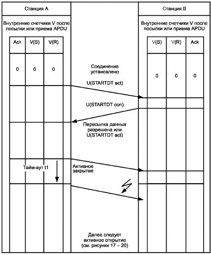
Thus, further it is necessary to count the bytes received from the controlling (master) station and disassemble them.
Sketch
uint8_t iec104ReciveArray[128];// EthernetClient client = iec104Server.available(); if(client.available()) { delay(100); int i = 0; while(client.available()) { iec104ReciveArray[i] = client.read();// i++; } After reading the data you need to parse them and form the answer.
Wireshark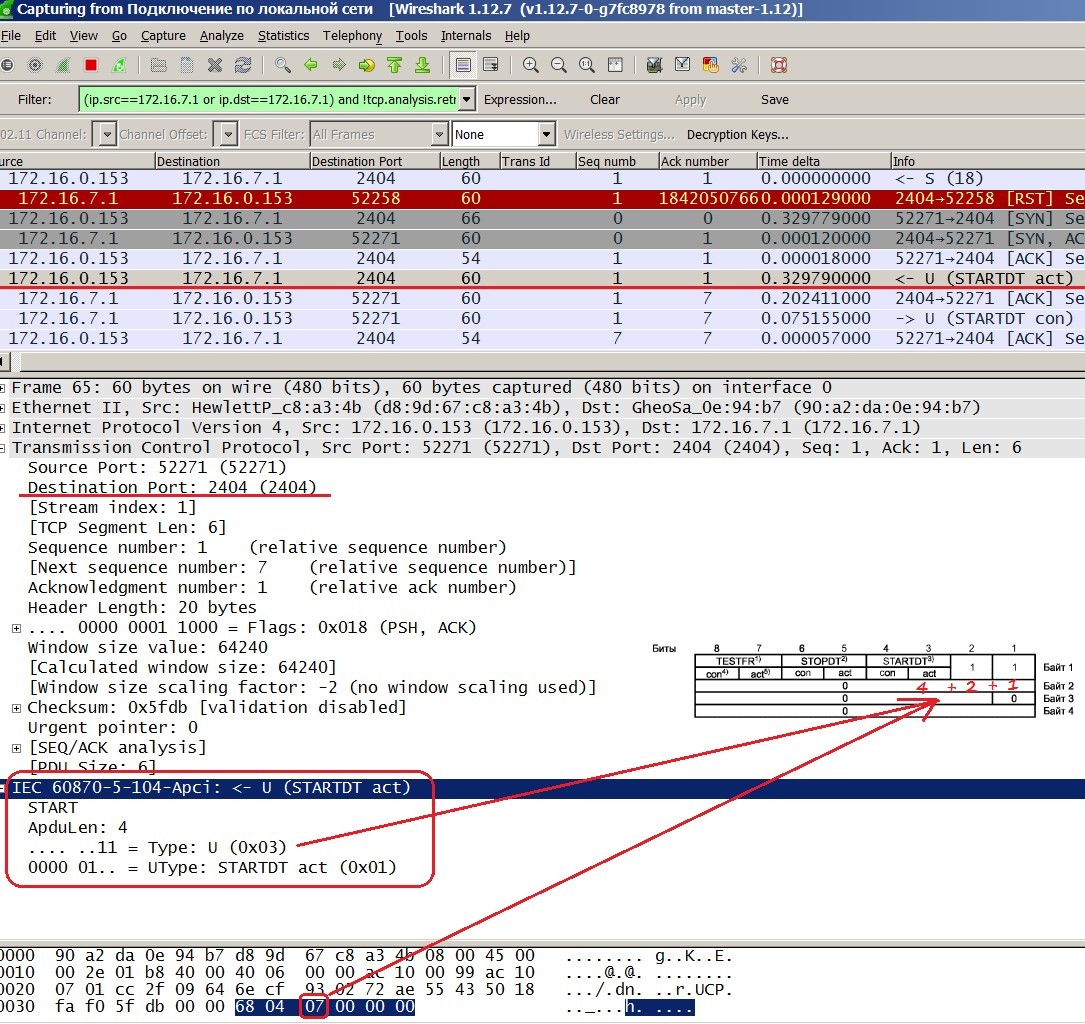
Here's what the package containing the STARTDT block in the Wireshark program looks like, the APDU is a U-format block that consists only of APCI.
APCI - Application Level Control Information can be used as a separate control frame (U frame or S frame).
In short, we can say that the APCI block determines the type of APDU block and its length. APCI consists of the following six bytes:
1. Sign of initialization of the variable-length APDU block, starting with START2 68h;
2. The length of the APDU, in this example is four bytes;
3. The control byte in which the type of APDU is determined, in this example, a value of seven is written, which means a request for data transfer;
4,5,6 Not used.
Based on the above, before answering, it would not hurt to determine what type of APDU the monitoring station sent us. Knowing that the type of APDU is written in the third order of reading the APCI block byte, I will save it in an integer variable.
Note: If an “I” format packet is received, then 3 bytes in APCI will also contain the low word value of the received packets counter,
therefore, we had to slightly complicate the construction of the definition of the type APDU.
Sketch
ASDU=iec104ReciveArray[6];// ASDU? switch (ASDU) { case 100:// TypeQuerry=iec104ReciveArray[2]-word(iec104ReciveArray[3],iec104ReciveArray[2]);// rxcnt+=2;// break; case 0: TypeQuerry=iec104ReciveArray[2]; // break; default : TypeQuerry=iec104ReciveArray[2];// break; } It can be seen from the figure above that the type of APDU corresponding to the value 7 is STARTDT act, respectively, it is necessary to respond with the same package structure, only the type value should have the value 11 (0b), which corresponds to STARTDT con.
Sketch
#include <Ethernet.h> byte mac[] = {0x90, 0xA2, 0xDA, 0x0E, 0x94, 0xB7 }; IPAddress ip(172, 16, 7, 1); IPAddress gateway(172, 16,7, 0); IPAddress subnet(255, 255, 0, 0); EthernetClient client; EthernetServer iec104Server(2404); int TypeQuerry, MessageLength;// APDU uint8_t iec104ReciveArray[128];// APDU void setup() { Ethernet.begin(mac, ip, gateway, subnet); } void loop() { client = iec104Server.available(); if(client.available())// { delay(100); int i = 0; while(client.available())// { iec104ReciveArray[i] = client.read();// i++; } TypeQuerry= iec104ReciveArray[2];// APDU switch(TypeQuerry) { case 07:// STARTDT iec104ReciveArray[0]=iec104ReciveArray[0];// START2 = 68h; iec104ReciveArray[1]=iec104ReciveArray[1];// APDU iec104ReciveArray[2] = iec104ReciveArray[2]+4; // APDU iec104ReciveArray[3]=0; iec104ReciveArray[4]=0; iec104ReciveArray[5]=0; MessageLength = iec104ReciveArray[1]+2;// + 2 Start and Lenght APCI delay(100); client.write(iec104ReciveArray, MessageLength);// break; } } } After updating the sketch, we observe the following order of exchange:
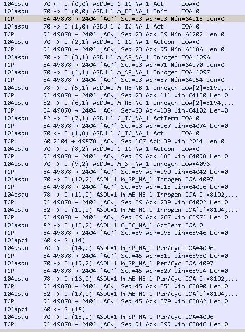
Establishing a connection, a request for data transfer, confirmation of the request and another new yet unknown APDU of format I type 1 C_IC_NA Act.
3. Request for a general station survey
The C_IC ACT polling command requests a full volume or a specified subset of polled information at a CP. A subset (group) is selected using the QOI polling descriptor.
The station polling team requires the monitored stations to transmit the current status of their information, usually transmitted sporadically (transmission cause = 3), to the monitoring station with transmission reasons from <20> to <36>. Station polling is used to synchronize information about the process at a monitoring station and monitored stations. It is also used to update the information at the monitoring station after the initialization procedure or after the monitoring station detects a loss of the channel (unsuccessful repetition of the data link layer request) and then recovers it. The response to the station survey should include process information objects that are stored at the monitored station. In response to polling the station, these information objects are transmitted with type identifiers <1>, <3>, <5>, <7>, <9>, <11>, <13>, <20> or <21> and can also transferred to other ASDUs with type identifiers from <1> to <14>, <20>, <21>, from <30> to <36> and with transmission reasons <1> - periodically / cyclically, <2> - background scanning or <3> - sporadically.
Picture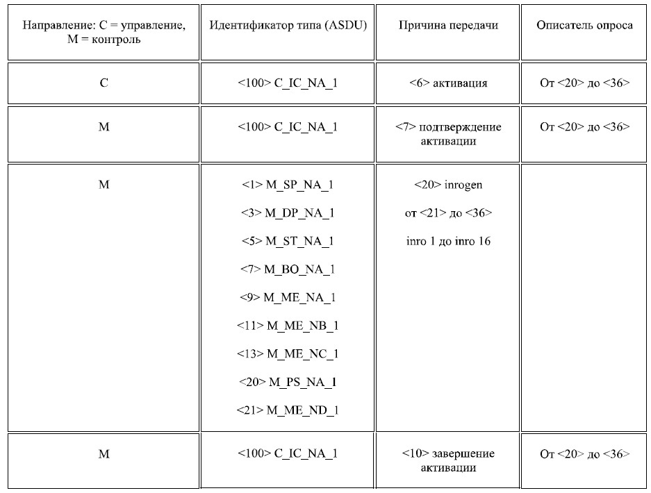
The APDU <100> C_IC_NA_1, in addition to the APCI block, also has an ASDU (Application Level Data Block), which together form the APDU Protocol Data Block of the Application Layer.
Consider in more detail the received APDU.
APCI:
- In the first byte, type 0 indicates that this is a polling command;
- In the second, the length of the APDU is 14 bytes;
ASDU:
- The first byte in the ASDU block determines the type of information object, in this case <100> C_IC_NA_1 (general station polling);
- The second data block structure;
- The third reason for the transfer (CauseTx), a value of six means an activation request;
- The fourth general address of the station;
- The fifth address of the controlled (slave) station;
- From the sixth to the eighth address of the information object is zero;
- The ninth information byte - QOI is a request handle that has the following values:
In response to <100> C_IC_NA_1, it is necessary to respond with a confirmation of the request, transfer the process information objects stored at the monitored station and complete the activation.
To send an acknowledgment, it is necessary in ASDU <100> C_IC_NA_1 to write to byte a value indicating the cause of transmission (CauseTX) equal to 7, to send the activation end to send the reason of transmission (CauseTX) equal to 10 to send the activation completion request.
Sketch
case 00:// txcnt=txcnt+02; // iec104ReciveArray[0]=iec104ReciveArray[0]; iec104ReciveArray[1]=iec104ReciveArray[1]; iec104ReciveArray[2]=lowByte(txcnt);//TX L iec104ReciveArray[3]=highByte(txcnt);//TX H iec104ReciveArray[4]=lowByte(rxcnt);//RX L iec104ReciveArray[5]=highByte(rxcnt);//RX H iec104ReciveArray[6]=100;// iec104ReciveArray[7]=01; iec104ReciveArray[8]=7;//cause Actcon iec104ReciveArray[9]=00;//OA iec104ReciveArray[10]=01;//Addr iec104ReciveArray[11]=00;//Addr iec104ReciveArray[12]=00;//IOA iec104ReciveArray[13]=00;//IOA iec104ReciveArray[14]=00;//IOA iec104ReciveArray[15]=20;//IOA, QOI MessageLength = iec104ReciveArray[1]+2; delay(100); client.write(iec104ReciveArray, MessageLength); txcnt=txcnt+2;// // iec104ReciveArray[0]=iec104ReciveArray[0]; iec104ReciveArray[1]=14;// APDU=APCI(4)+ ASDU(10) iec104ReciveArray[2]=lowByte(txcnt); iec104ReciveArray[3]=highByte(txcnt); iec104ReciveArray[4]=lowByte(rxcnt); iec104ReciveArray[5]=highByte(rxcnt); iec104ReciveArray[6]=1;//type 1 iec104ReciveArray[7]=01;//sq iec104ReciveArray[8]=20;//Cause Inrogen iec104ReciveArray[9]=00;//AO iec104ReciveArray[10]=01;//Adress iec104ReciveArray[11]=00;//Adress iec104ReciveArray[12]=iecData[0];//IOA iec104ReciveArray[13]=iecData[1];//IOA iec104ReciveArray[14]=0;//IOA iec104ReciveArray[15]=iecData[2];//value [DATA 1] MessageLength = iec104ReciveArray[1]+2; client.write(iec104ReciveArray, MessageLength); txcnt=txcnt+2; iec104ReciveArray[0]=iec104ReciveArray[0]; iec104ReciveArray[1]=14; iec104ReciveArray[2]=lowByte(txcnt); iec104ReciveArray[3]=highByte(txcnt); iec104ReciveArray[4]=lowByte(rxcnt); iec104ReciveArray[5]=highByte(rxcnt); iec104ReciveArray[6]=1;//type 1 bool iec104ReciveArray[7]=01; iec104ReciveArray[8]=20;//Cause Inrogen iec104ReciveArray[9]=00; iec104ReciveArray[10]=01; iec104ReciveArray[11]=00; iec104ReciveArray[12]=iecData[3]; iec104ReciveArray[13]=iecData[4]; iec104ReciveArray[14]=0; iec104ReciveArray[15]=iecData[5]; MessageLength = iec104ReciveArray[1]+2; client.write(iec104ReciveArray, MessageLength); delay(5); txcnt=txcnt+2; iec104ReciveArray[0]=iec104ReciveArray[0]; iec104ReciveArray[1]=22; iec104ReciveArray[2]=lowByte(txcnt); iec104ReciveArray[3]=highByte(txcnt); iec104ReciveArray[4]=lowByte(rxcnt); iec104ReciveArray[5]=highByte(rxcnt); iec104ReciveArray[6]=11;//type 11 int iec104ReciveArray[7]=02;//sq iec104ReciveArray[8]=20;//Cause Inrogen iec104ReciveArray[9]=00;//AO iec104ReciveArray[10]=01;//Adress iec104ReciveArray[11]=00;//Adress iec104ReciveArray[12]=iecData[6];//IOA iec104ReciveArray[13]=iecData[7];//IOA iec104ReciveArray[14]=0;//IOA iec104ReciveArray[15]=iecData[8];//value [DATA 1] iec104ReciveArray[16]=iecData[9];//value [DATA 1] iec104ReciveArray[17]=iecData[10];//QDS iec104ReciveArray[18]=iecData[11];//IOA iec104ReciveArray[19]=iecData[12];//OA iec104ReciveArray[20]=0;//IOA iec104ReciveArray[21]=iecData[13];//value [DATA 2] iec104ReciveArray[22]=iecData[14];//value [DATA 2] iec104ReciveArray[23]=iecData[15];//IOA QDS MessageLength = iec104ReciveArray[1]+2; client.write(iec104ReciveArray, MessageLength); delay(5); txcnt=txcnt+2; iec104ReciveArray[0]=iec104ReciveArray[0]; iec104ReciveArray[1]=26; iec104ReciveArray[2]=lowByte(txcnt); iec104ReciveArray[3]=highByte(txcnt); iec104ReciveArray[4]=lowByte(rxcnt); iec104ReciveArray[5]=highByte(rxcnt); iec104ReciveArray[6]=13;//type 13 Float iec104ReciveArray[7]=02;//sq iec104ReciveArray[8]=20;//Cause Inrogen iec104ReciveArray[9]=00;//AO iec104ReciveArray[10]=01;//Adress iec104ReciveArray[11]=00;//Adress iec104ReciveArray[12]=iecData[16];//IOA iec104ReciveArray[13]=iecData[17];//IOA iec104ReciveArray[14]=0; iec104ReciveArray[15]=iecData[18];//value [DATA 1] iec104ReciveArray[16]=iecData[19];//value [DATA 1] iec104ReciveArray[17]=iecData[20];//value [DATA 1] iec104ReciveArray[18]=iecData[21];//value [DATA 1] iec104ReciveArray[19]=iecData[22];//IOA QDS iec104ReciveArray[20]=iecData[23];//IOA iec104ReciveArray[21]=iecData[24];//IOA iec104ReciveArray[22]=0;//IOA iec104ReciveArray[23]=iecData[25];//value [DATA 2] iec104ReciveArray[24]=iecData[26];//value [DATA 2] iec104ReciveArray[25]=iecData[27];//value [DATA 2] iec104ReciveArray[26]=iecData[28];//value [DATA 2] iec104ReciveArray[27]=iecData[29];//IOA QDS MessageLength = iec104ReciveArray[1]+2; client.write(iec104ReciveArray, MessageLength); txcnt=txcnt+2; // iec104ReciveArray[0]=iec104ReciveArray[0]; iec104ReciveArray[1]=iec104ReciveArray[1]; iec104ReciveArray[2]=lowByte(txcnt); iec104ReciveArray[3]=highByte(txcnt); iec104ReciveArray[4]=lowByte(rxcnt); iec104ReciveArray[5]=highByte(rxcnt); iec104ReciveArray[6]=100;//type iec104ReciveArray[7]=01;//sq iec104ReciveArray[8]=10;//cause AckTerm iec104ReciveArray[9]=00; iec104ReciveArray[10]=01; iec104ReciveArray[11]=00; iec104ReciveArray[12]=00; iec104ReciveArray[13]=00; iec104ReciveArray[14]=00; iec104ReciveArray[15]=20; MessageLength = iec104ReciveArray[1]+2; client.write(iec104ReciveArray, MessageLength); iec104ReciveArray[6]=00;// break; After updating the sketch, we observe the following order of exchange:
Establish a connection, request for data transmission, confirmation, request for a general interrogation of a station from a monitoring station, completion of initialization, request for a general interrogation of a station to the direction of a controlled station, confirmation of a general interrogation, forwarding the values of all available signals at the monitoring station, completion of a general interrogation and unknown APCI format S.
The station inquiry request is issued in the direction of the monitored station:
- if “END OF INITIALIZATION” is received from the controlled station or
- if the central station detects a loss of the channel (unsuccessful repeated request of the data link layer) and its subsequent recovery.
4. Preparation and transmission of data
An APDU S format block consisting only of APCI is intended to confirm the received APDU I format. For S-format 7, the upper bits of the service field of byte 1 and byte 2 are not involved, and byte 3 (7 high bits) and byte 4 determine the current number of the received parcel.
In this case, the S block indicates that the controlling (master) station is ready to receive data within a certain time, not exceeding, the timeout t3 determined on the side of the controlling (master) station. That is, the master station tells us "I am ready to receive data!". Next, you need to take care of what data to transfer and where to get it.
What can be transmitted? There are several types of information defined in IEC 870-5- 104:
- Control;
- The manager;
- Options;
- File transfer
Picture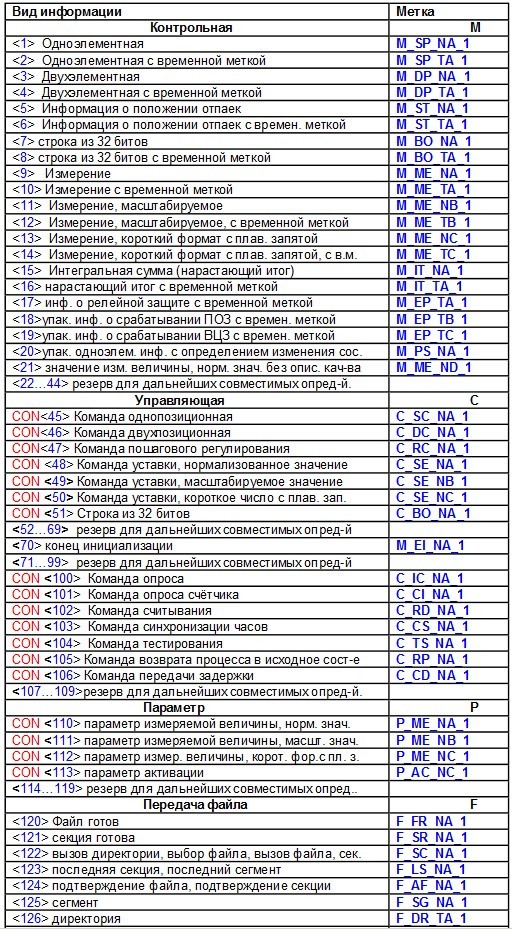
In this example, the transfer of control information is considered using examples 1, 11 and 13 of functions (single-element, measurement scalable, measurement short format with a floating point). Data is generated randomly. It is also necessary to take into account that each transmitted signal has a quality byte.
A simple algorithm for determining the quality of the signal:
- If a substitution of an active signal is used, then the BL (blocking) and SB (substitution) flags are set;
- If the signal value did not change during the control period of time, then the NT flag is set (not relevant);
- If there is a sign of inoperability of a node or device of a lower level (sensor or other), then flag IV is set (not a valid value).
Sketch
void SetQDS(int currvalue, int i,bool zam)// { if (zam==0)//? { if (currvalue==previusValue[i])// ? { previusValue[i]=currvalue; counter[i]+=1; if (counter[i]>=1000) { qds[i]=64;// NT counter[i]=0; } } else { qds[i]=0; counter[i]=0; previusValue[i]=currvalue; } } else { qds[i]=48;// SB, BL } } It is also necessary to take into account that for each signal there is a unique identifier IOA, in the power industry it is customary to allocate these addresses as follows:
- TC-starting from 4096;
- TI-starting from 8192;
- TU-starting from 20480.
To transfer the values of signals to an array for sending, use the EEPROM library:
Sketch
void EEPROM_float_write(int addr, float val,int IOA,int number,bool subs) // EEPROM, , , , { SetQDS(val,number, subs);// byte *x = (byte *)&val;//float -->byte byte *xxx = (byte *)&IOA;// IOA for(int jj = 0; jj <2; jj++) { EEPROM.write(addr,xxx[jj]);// EEPROM 2 addr+=1; } for(byte i = 0; i < 4; i++) // float 4 { EEPROM.write(addr, x[i]); // float 4 addr+=1; } EEPROM.write(addr, qds[number]);// if (addr == EEPROM.length()) { addr = 0; } } And so having received the APDU confirmation S or I format from the monitoring station, you can begin to transmit the available data, not forgetting to increase the number of the transmitted frame.
Sketch
#include <eeprom.h> #include <Ethernet.h> #include <eeprom.h> byte mac[] = {0x90, 0xA2, 0xDA, 0x0E, 0x94, 0xB7 }; IPAddress ip(172, 16, 7, 1); IPAddress gateway(172, 16,7, 0); IPAddress subnet(255, 255, 0, 0); EthernetClient client; EthernetServer iec104Server(2404); int TypeQuerry, MessageLength; uint8_t iec104ReciveArray[128]; int counter[6];// int qds[6];// int previusValue[6];// NT word iecData[256];// int ASDU;// int txcnt, rxcnt;// void setup() { // 2404 Ethernet.begin(mac, ip, gateway, subnet); Serial.begin(9600); } void EEPROM_float_write(int addr, float val,int IOA,int number,bool zam) // Float 13 { SetQDS(val,number,zam);// byte *x = (byte *)&val; byte *xxx = (byte *)&IOA; for(int jj = 0; jj <2; jj++)// IOA 2 { EEPROM.write(addr,xxx[jj]); addr+=1; } for(byte i = 0; i < 4; i++)// float 4 { EEPROM.write(addr, x[i]); addr+=1; } EEPROM.write(addr, qds[number]); if (addr == EEPROM.length()) { addr = 0; } } void EEPROM_byte_write(int addr, bool val,int IOA,int number,bool zam) // Bool 1 { SetQDS(val,number,zam);// byte c=val+qds[number]; byte *x = (byte *)&c; byte *xxxx = (byte *)&IOA; for(int jj = 0; jj <2; jj++) // IOA 2 { EEPROM.write(addr,xxxx[jj]); addr+=1; } for(byte i = 0; i < 1; i++) // bool + 1 { EEPROM.write(addr, x[i]); } if (addr == EEPROM.length()) { addr = 0; } } void EEPROM_int_write(int addr, int val, int IOA,int number,bool zam) // Int 11 { SetQDS(val,number,zam); // byte *x = (byte *)&val; byte *xx = (byte *)&IOA; for(int jj = 0; jj <2; jj++)// IOA 2 { EEPROM.write(addr,xx[jj]); addr+=1; } for(byte i = 0; i < 2; i++)// int 2 a { EEPROM.write(addr, x[i]); addr+=1; } EEPROM.write(addr, qds[number]); if (addr == EEPROM.length()) { addr = 0; } } // void SetQDS(int currvalue, int i,bool zam)// , , { if (zam==0)//? { if (currvalue==previusValue[i])// ? { previusValue[i]=currvalue; counter[i]+=1; if (counter[i]>=1000) { qds[i]=64;// NT counter[i]=0; } } else { qds[i]=0; counter[i]=0; previusValue[i]=currvalue; } } else { qds[i]=48;// } } void loop() { // 1,11,13 // : ( EEPROM, , IOA , ) EEPROM_byte_write(0,0,4096,0,0); EEPROM_byte_write(3,random(0, 2),4097,1,1); EEPROM_int_write(6, 67,8192,2,1); EEPROM_int_write(11, random(10, 20),8193,3,0); EEPROM_float_write(16, random(-1000, 2000),8194,4,1); EEPROM_float_write(23, 78.66f,8195,5,1); client = iec104Server.available(); if(client.available()) { delay(100); int i = 0; while(client.available()) { iec104ReciveArray[i] = client.read();// i++; } ASDU=iec104ReciveArray[6];// ASDU? switch (ASDU) { case 100:// TypeQuerry=iec104ReciveArray[2]-word(iec104ReciveArray[3],iec104ReciveArray[2]); rxcnt+=2;// break; case 0: TypeQuerry=iec104ReciveArray[2];// break; default : TypeQuerry=iec104ReciveArray[2]; break; } for(byte z = 0; z <64; z++) // { iecData[z]= EEPROM.read(z); } // APDU switch(TypeQuerry) { case 07://APDU STARTDT rxcnt=0; txcnt=0; iec104ReciveArray[0]=iec104ReciveArray[0];// , START2 = 68h; iec104ReciveArray[1]=iec104ReciveArray[1];// APDU iec104ReciveArray[2]=11;//STARTDT con iec104ReciveArray[3]=0; iec104ReciveArray[4]=0; iec104ReciveArray[5]=0; MessageLength = iec104ReciveArray[1]+2;// client.write(iec104ReciveArray, MessageLength);// // iec104ReciveArray[0]=iec104ReciveArray[0];// , START2 = 68h; iec104ReciveArray[1]=14;// APDU iec104ReciveArray[2]=0;//, TX L iec104ReciveArray[3]=0;//TX H iec104ReciveArray[4]=0;//RX L iec104ReciveArray[5]=0;//RX H iec104ReciveArray[6]=70;//type End of Init iec104ReciveArray[7]=01;//sq iec104ReciveArray[8]=04;//cause Init iec104ReciveArray[9]=00;//AO iec104ReciveArray[10]=01;//Adress iec104ReciveArray[11]=00;//Adress iec104ReciveArray[12]=00;//IOA iec104ReciveArray[13]=00;//IOA iec104ReciveArray[14]=00;//IOA iec104ReciveArray[15]=129;//IOA, COI MessageLength = iec104ReciveArray[1]+2; client.write(iec104ReciveArray, MessageLength); // iec104ReciveArray[0]=iec104ReciveArray[0]; iec104ReciveArray[1]=14;// APDU iec104ReciveArray[2]=2;//TX L iec104ReciveArray[3]=0;//TX H iec104ReciveArray[4]=0;//RX L iec104ReciveArray[5]=0;//RX H iec104ReciveArray[6]=100;// iec104ReciveArray[7]=01; iec104ReciveArray[8]=6;//cause Act iec104ReciveArray[9]=00; iec104ReciveArray[10]=01; iec104ReciveArray[11]=00; iec104ReciveArray[12]=00; iec104ReciveArray[13]=00; iec104ReciveArray[14]=00; iec104ReciveArray[15]=20;//IOA, QOI MessageLength = iec104ReciveArray[1]+2; client.write(iec104ReciveArray, MessageLength); txcnt=txcnt+02; break; case 00:// txcnt=txcnt+02; // iec104ReciveArray[0]=iec104ReciveArray[0]; iec104ReciveArray[1]=iec104ReciveArray[1]; iec104ReciveArray[2]=lowByte(txcnt);//TX L iec104ReciveArray[3]=highByte(txcnt);//TX H iec104ReciveArray[4]=lowByte(rxcnt);//RX L iec104ReciveArray[5]=highByte(rxcnt);//RX H iec104ReciveArray[6]=100;// iec104ReciveArray[7]=01; iec104ReciveArray[8]=7;//cause Actcon iec104ReciveArray[9]=00;//OA iec104ReciveArray[10]=01;//Addr iec104ReciveArray[11]=00;//Addr iec104ReciveArray[12]=00;//IOA iec104ReciveArray[13]=00;//IOA iec104ReciveArray[14]=00;//IOA iec104ReciveArray[15]=20;//IOA, QOI MessageLength = iec104ReciveArray[1]+2; delay(100); client.write(iec104ReciveArray, MessageLength); txcnt=txcnt+2;// // iec104ReciveArray[0]=iec104ReciveArray[0]; iec104ReciveArray[1]=14;// APDU=APCI(4)+ ASDU(10) iec104ReciveArray[2]=lowByte(txcnt); iec104ReciveArray[3]=highByte(txcnt); iec104ReciveArray[4]=lowByte(rxcnt); iec104ReciveArray[5]=highByte(rxcnt); iec104ReciveArray[6]=1;//type 1 iec104ReciveArray[7]=01;//sq iec104ReciveArray[8]=20;//Inrogen iec104ReciveArray[9]=00;//AO iec104ReciveArray[10]=01;//Adress iec104ReciveArray[11]=00;//Adress iec104ReciveArray[12]=iecData[0];//IOA iec104ReciveArray[13]=iecData[1];//IOA iec104ReciveArray[14]=0;//IOA iec104ReciveArray[15]=iecData[2];//value [DATA 1] MessageLength = iec104ReciveArray[1]+2; client.write(iec104ReciveArray, MessageLength); txcnt=txcnt+2; iec104ReciveArray[0]=iec104ReciveArray[0]; iec104ReciveArray[1]=14; iec104ReciveArray[2]=lowByte(txcnt); iec104ReciveArray[3]=highByte(txcnt); iec104ReciveArray[4]=lowByte(rxcnt); iec104ReciveArray[5]=highByte(rxcnt); iec104ReciveArray[6]=1; iec104ReciveArray[7]=01; iec104ReciveArray[8]=20; iec104ReciveArray[9]=00; iec104ReciveArray[10]=01; iec104ReciveArray[11]=00; iec104ReciveArray[12]=iecData[3]; iec104ReciveArray[13]=iecData[4]; iec104ReciveArray[14]=0; iec104ReciveArray[15]=iecData[5]; MessageLength = iec104ReciveArray[1]+2; client.write(iec104ReciveArray, MessageLength); delay(5); txcnt=txcnt+2; iec104ReciveArray[0]=iec104ReciveArray[0]; iec104ReciveArray[1]=22; iec104ReciveArray[2]=lowByte(txcnt); iec104ReciveArray[3]=highByte(txcnt); iec104ReciveArray[4]=lowByte(rxcnt); iec104ReciveArray[5]=highByte(rxcnt); iec104ReciveArray[6]=11;//type 11 iec104ReciveArray[7]=02;//sq iec104ReciveArray[8]=20;//cause iec104ReciveArray[9]=00;//AO iec104ReciveArray[10]=01;//Adress iec104ReciveArray[11]=00;//Adress iec104ReciveArray[12]=iecData[6];//IOA iec104ReciveArray[13]=iecData[7];//IOA iec104ReciveArray[14]=0;//IOA iec104ReciveArray[15]=iecData[8];//value [DATA 1] iec104ReciveArray[16]=iecData[9];//value [DATA 1] iec104ReciveArray[17]=iecData[10];//QDS iec104ReciveArray[18]=iecData[11];//IOA iec104ReciveArray[19]=iecData[12];//OA iec104ReciveArray[20]=0;//IOA iec104ReciveArray[21]=iecData[13];//value [DATA 2] iec104ReciveArray[22]=iecData[14];//value [DATA 2] iec104ReciveArray[23]=iecData[15];//IOA QDS MessageLength = iec104ReciveArray[1]+2; client.write(iec104ReciveArray, MessageLength); delay(5); txcnt=txcnt+2; iec104ReciveArray[0]=iec104ReciveArray[0]; iec104ReciveArray[1]=26; iec104ReciveArray[2]=lowByte(txcnt); iec104ReciveArray[3]=highByte(txcnt); iec104ReciveArray[4]=lowByte(rxcnt); iec104ReciveArray[5]=highByte(rxcnt); iec104ReciveArray[6]=13;//type 13 iec104ReciveArray[7]=02;//sq iec104ReciveArray[8]=20;//cause iec104ReciveArray[9]=00;//AO iec104ReciveArray[10]=01;//Adress iec104ReciveArray[11]=00;//Adress iec104ReciveArray[12]=iecData[16];//IOA iec104ReciveArray[13]=iecData[17];//IOA iec104ReciveArray[14]=0; iec104ReciveArray[15]=iecData[18];//value [DATA 1] iec104ReciveArray[16]=iecData[19];//value [DATA 1] iec104ReciveArray[17]=iecData[20];//value [DATA 1] iec104ReciveArray[18]=iecData[21];//value [DATA 1] iec104ReciveArray[19]=iecData[22];//IOA QDS iec104ReciveArray[20]=iecData[23];//IOA iec104ReciveArray[21]=iecData[24];//IOA iec104ReciveArray[22]=0;//IOA iec104ReciveArray[23]=iecData[25];//value [DATA 2] iec104ReciveArray[24]=iecData[26];//value [DATA 2] iec104ReciveArray[25]=iecData[27];//value [DATA 2] iec104ReciveArray[26]=iecData[28];//value [DATA 2] iec104ReciveArray[27]=iecData[29];//IOA QDS MessageLength = iec104ReciveArray[1]+2; client.write(iec104ReciveArray, MessageLength); txcnt=txcnt+2; // iec104ReciveArray[0]=iec104ReciveArray[0]; iec104ReciveArray[1]=iec104ReciveArray[1]; iec104ReciveArray[2]=lowByte(txcnt); iec104ReciveArray[3]=highByte(txcnt); iec104ReciveArray[4]=lowByte(rxcnt); iec104ReciveArray[5]=highByte(rxcnt); iec104ReciveArray[6]=100;//type iec104ReciveArray[7]=01;//sq iec104ReciveArray[8]=10;//cause AckTerm iec104ReciveArray[9]=00; iec104ReciveArray[10]=01; iec104ReciveArray[11]=00; iec104ReciveArray[12]=00; iec104ReciveArray[13]=00; iec104ReciveArray[14]=00; iec104ReciveArray[15]=20; MessageLength = iec104ReciveArray[1]+2; client.write(iec104ReciveArray, MessageLength); iec104ReciveArray[6]=00;// break; //APDU S case 01: txcnt=word(iec104ReciveArray[5],iec104ReciveArray[4]); iec104ReciveArray[0]=iec104ReciveArray[0]; iec104ReciveArray[1]=14; iec104ReciveArray[2]=lowByte(txcnt); iec104ReciveArray[3]=highByte(txcnt); iec104ReciveArray[4]=lowByte(rxcnt); iec104ReciveArray[5]=highByte(rxcnt); iec104ReciveArray[6]=1;//type 1 iec104ReciveArray[7]=01;//sq iec104ReciveArray[8]=01;//cause Cycl iec104ReciveArray[9]=00;//AO iec104ReciveArray[10]=01;//Adress iec104ReciveArray[11]=00;//Adress iec104ReciveArray[12]=iecData[0];//IOA iec104ReciveArray[13]=iecData[1];//IOA iec104ReciveArray[14]=0;//IOA iec104ReciveArray[15]=iecData[2];//value [DATA 1] MessageLength = iec104ReciveArray[1]+2; client.write(iec104ReciveArray, MessageLength); delay(5); txcnt=txcnt+2; iec104ReciveArray[0]=iec104ReciveArray[0]; iec104ReciveArray[1]=14; iec104ReciveArray[2]=lowByte(txcnt); iec104ReciveArray[3]=highByte(txcnt); iec104ReciveArray[4]=lowByte(rxcnt); iec104ReciveArray[5]=highByte(rxcnt); iec104ReciveArray[6]=1;//type 1 Bool iec104ReciveArray[7]=01;//sq iec104ReciveArray[8]=01;//cause Cycl iec104ReciveArray[9]=00;//AO iec104ReciveArray[10]=01;//Adress iec104ReciveArray[11]=00;//Adress iec104ReciveArray[12]=iecData[3];//IOA iec104ReciveArray[13]=iecData[4];//IOA iec104ReciveArray[14]=0;//IOA iec104ReciveArray[15]=iecData[5];//value [DATA 1] MessageLength = iec104ReciveArray[1]+2; client.write(iec104ReciveArray, MessageLength); delay(5); txcnt=txcnt+2; iec104ReciveArray[0]=iec104ReciveArray[0]; iec104ReciveArray[1]=22; iec104ReciveArray[2]=lowByte(txcnt); iec104ReciveArray[3]=highByte(txcnt); iec104ReciveArray[4]=lowByte(rxcnt); iec104ReciveArray[5]=highByte(rxcnt); iec104ReciveArray[6]=11;//type 11 Int iec104ReciveArray[7]=02;//sq iec104ReciveArray[8]=01;//cause Cycl iec104ReciveArray[9]=00;//AO iec104ReciveArray[10]=01;//Adress iec104ReciveArray[11]=00;//Adress iec104ReciveArray[12]=iecData[6];//IOA iec104ReciveArray[13]=iecData[7];//IOA iec104ReciveArray[14]=0;//IOA iec104ReciveArray[15]=iecData[8];//value [DATA 1] iec104ReciveArray[16]=iecData[9];//value [DATA 1] iec104ReciveArray[17]=iecData[10];//QDS iec104ReciveArray[18]=iecData[11];//IOA iec104ReciveArray[19]=iecData[12];//OA iec104ReciveArray[20]=0;//IOA iec104ReciveArray[21]=iecData[13];//value [DATA 2] iec104ReciveArray[22]=iecData[14];//value [DATA 2] iec104ReciveArray[23]=iecData[15];//IOA QDS MessageLength = iec104ReciveArray[1]+2; client.write(iec104ReciveArray, MessageLength); delay(5); txcnt=txcnt+2; iec104ReciveArray[0]=iec104ReciveArray[0]; iec104ReciveArray[1]=26; iec104ReciveArray[2]=lowByte(txcnt); iec104ReciveArray[3]=highByte(txcnt); iec104ReciveArray[4]=lowByte(rxcnt); iec104ReciveArray[5]=highByte(rxcnt); iec104ReciveArray[6]=13;//type 13 Float iec104ReciveArray[7]=02;//sq iec104ReciveArray[8]=01;//cause Cycl iec104ReciveArray[9]=00;//AO iec104ReciveArray[10]=01;//Adress iec104ReciveArray[11]=00;//Adress iec104ReciveArray[12]=iecData[16];//IOA iec104ReciveArray[13]=iecData[17];//IOA iec104ReciveArray[14]=0; iec104ReciveArray[15]=iecData[18];//value [DATA 1] iec104ReciveArray[16]=iecData[19];//value [DATA 1] iec104ReciveArray[17]=iecData[20];//value [DATA 1] iec104ReciveArray[18]=iecData[21];//value [DATA 1] iec104ReciveArray[19]=iecData[22];//IOA QDS iec104ReciveArray[20]=iecData[23];//IOA iec104ReciveArray[21]=iecData[24];//IOA iec104ReciveArray[22]=0;//IOA iec104ReciveArray[23]=iecData[25];//value [DATA 2] iec104ReciveArray[24]=iecData[26];//value [DATA 2] iec104ReciveArray[25]=iecData[27];//value [DATA 2] iec104ReciveArray[26]=iecData[28];//value [DATA 2] iec104ReciveArray[27]=iecData[29];//IOA QDS MessageLength = iec104ReciveArray[1]+2; client.write(iec104ReciveArray, MessageLength); txcnt=txcnt; break; case 67: //TESTFR iec104ReciveArray[0]=iec104ReciveArray[0]; iec104ReciveArray[1]=iec104ReciveArray[1]; iec104ReciveArray[2] =131; //TESTFR con iec104ReciveArray[3] =0; iec104ReciveArray[4] =0; iec104ReciveArray[5] =0; MessageLength = iec104ReciveArray[1]+2; delay(10); client.write(iec104ReciveArray, MessageLength); iec104ReciveArray[0]=iec104ReciveArray[0]; iec104ReciveArray[1]=26;// APDU iec104ReciveArray[2]=lowByte(txcnt); iec104ReciveArray[3]=highByte(txcnt); iec104ReciveArray[4]=lowByte(rxcnt); iec104ReciveArray[5]=highByte(rxcnt); iec104ReciveArray[6]=13;//type 13 iec104ReciveArray[7]=02;//sq iec104ReciveArray[8]=03;//spont iec104ReciveArray[9]=00;//AO iec104ReciveArray[10]=01;//Adress iec104ReciveArray[11]=00;//Adress iec104ReciveArray[12]=iecData[16];//IOA iec104ReciveArray[13]=iecData[17];//IOA iec104ReciveArray[14]=0; iec104ReciveArray[15]=iecData[18];//value [DATA 1] iec104ReciveArray[16]=iecData[19];//value [DATA 1] iec104ReciveArray[17]=iecData[20];//value [DATA 1] iec104ReciveArray[18]=iecData[21];//value [DATA 1] iec104ReciveArray[19]=iecData[22];//IOA QDS iec104ReciveArray[20]=iecData[23];//IOA iec104ReciveArray[21]=iecData[24];//IOA iec104ReciveArray[22]=0;//IOA iec104ReciveArray[23]=iecData[25]; iec104ReciveArray[24]=iecData[26]; iec104ReciveArray[25]=iecData[27]; iec104ReciveArray[26]=iecData[28]; iec104ReciveArray[27]=iecData[29];//IOA QDS MessageLength = iec104ReciveArray[1]+2; client.write(iec104ReciveArray, MessageLength); break; } } } After uploading the sketch to Wireshark, we observe that data transfer has finally begun.
Next, I provide a description of the structure of the ASDU <100> M_SP_NA_1 single-element indication.
TypeId is a type of information.
SQ - variable structure classifier.
Two structures of data blocks are provided for:
1. A block containing i information objects, each of which contains one information item (or one combination of elements); the high-order bit of the classifier for the variable structure SQ (single / sequence) is 0, the remaining 7 bits specify the number i.
2. A block containing a single information object that contains j elements or the same combinations of information elements; the most significant bit (27 = 80h) of the SQ classifier is 1, the remaining 7 bits specify the number j.
Picture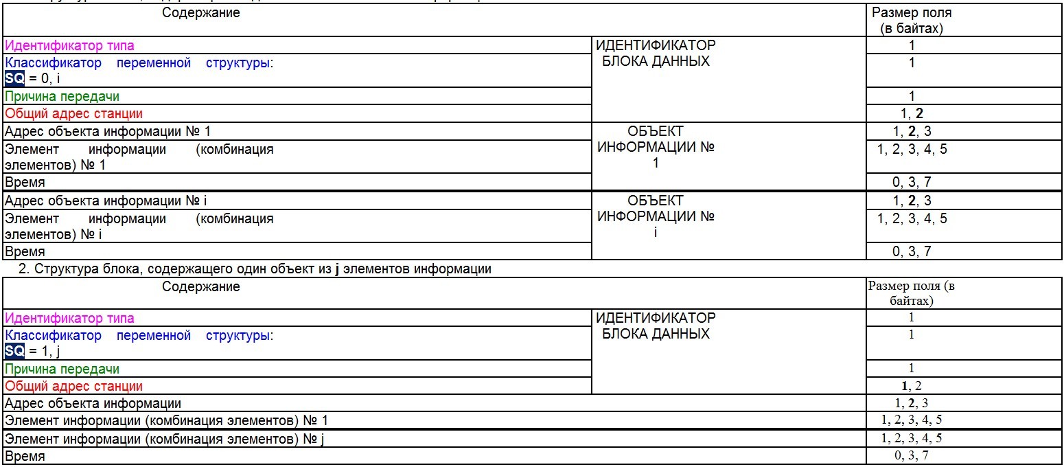
CauseTx - the reason for the transfer.
Picture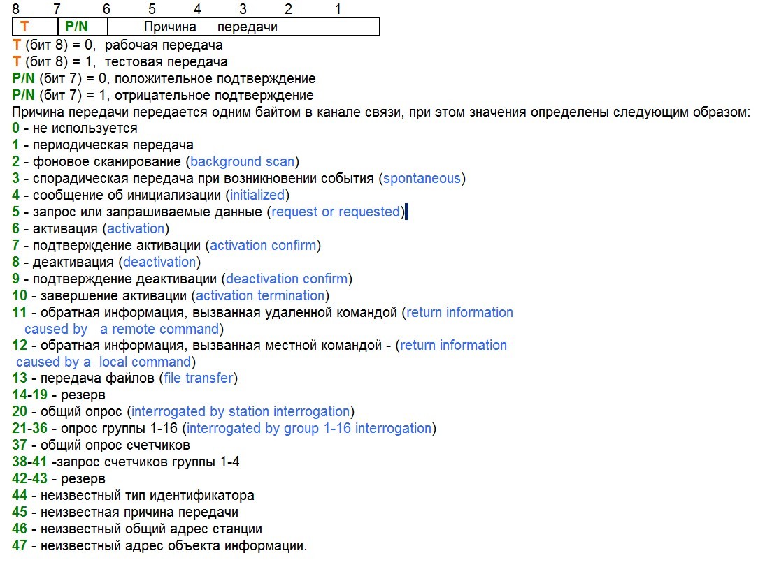
Addr - slave address (specified when configuring the wizard).
IOA is the address of the information object; at this address, the monitoring station will link its
SIQ tag — the quality indicator of the transmitted signal.
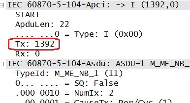
The ASDU structure of the function block <11> M_ME_NB_1 :
Wireshark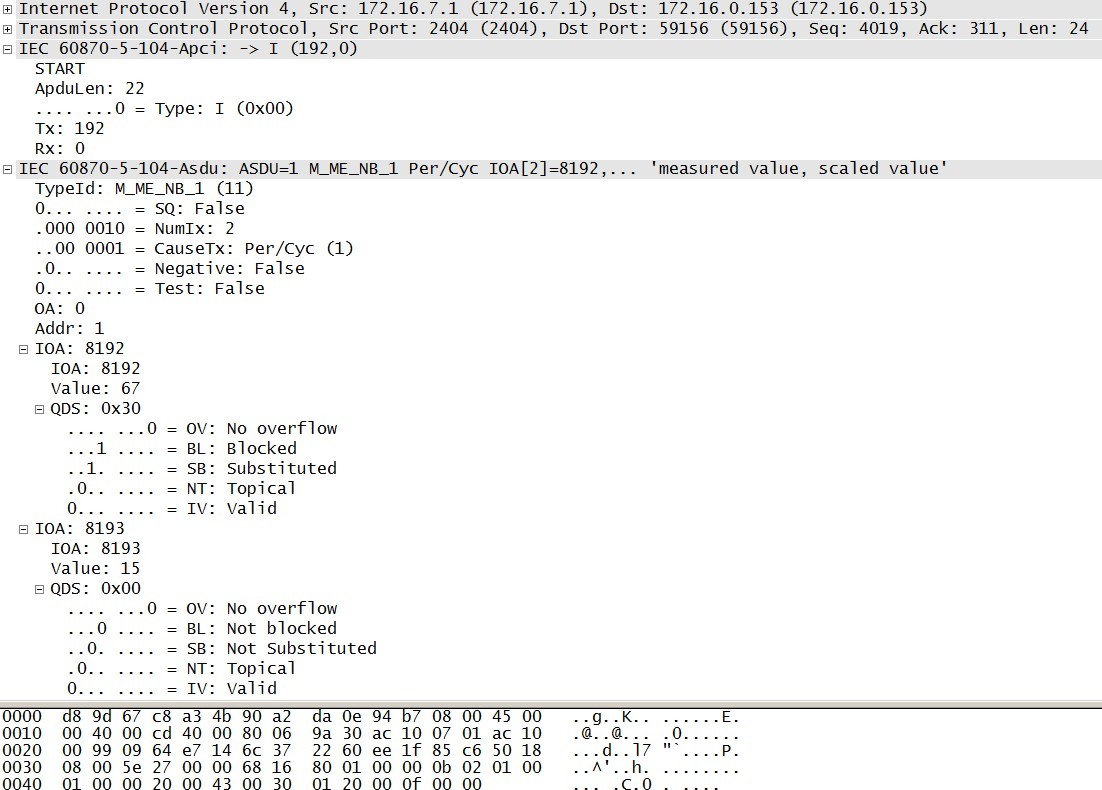
In response to the received data, the master will send blocks of format S and the process will loop until the monitored (slave) device stops transmitting frames.
5. Testing procedures
Testing procedures are used to monitor the performance of transport connections. The procedure is performed independently of the “activity” of the IP connection, if during the control time t3 no frames were received (I, U, S). Time t3 is subject to negotiation and is called “Time out for sending test blocks in case of long idle time”. The test procedure is implemented by sending a test APDU (TESTFR = act), which is confirmed by the received station using the APDU (TESTFR = con).
Picture
Wireshark
If the control station (master) receives an APDU whose value in the byte responsible for the type of APDU is sixty network (TESTFR), it means that during the time t3, no frame was received from the monitored station (I, U, S) , and if during the time t1 does not respond with a confirmation, the connection will be terminated.
Sketch
case 67: iec104ReciveArray[0]=iec104ReciveArray[0];// , START2 = 68h; iec104ReciveArray[1]=iec104ReciveArray[1];// APDU LENGHT iec104ReciveArray[2] = 131; //TESTDT con iec104ReciveArray[3] =0; iec104ReciveArray[4] =0; iec104ReciveArray[5] =0; MessageLength = iec104ReciveArray[1]+2;// + 2 Start68H and Lenght delay(10); client.write(iec104ReciveArray, MessageLength); Wireshark
That's all, if anyone is interested, then in the next article I will look at the IEC 670-5-104 protocol from the controlling (master) station using the example of Arduino.
Source: https://habr.com/ru/post/280818/
All Articles