Quad-tree live visualization on Shader Model 2.0
Prologue
Good day! Once a friend came to my job, and I showed him my freshly written shader, at that time it was the first serious experience with them. This firmware converted the image from the camera into the image of a knitted sweater.
At the time of development, the image was taken from the camera of the phone and displayed in a knitted form, the effect was unusual. And a friend threw an idea to make a filter for the camera in the form of a quadratic tree.
')
In general, from that moment I sat down to study the methods of quickly constructing a quadratic tree, and stopped at the idea of HistoPyramid .
Implementation
Initially, you need to prepare the input parameters for the shader. I used Unity3D, so C # code samples.
The process of the algorithm is divided into two stages:
- Building a tree
- but. Shader Parameters Preparation
b. Shader implementation - Creating an image from a tree
Building a tree
Shader Parameters Preparation
All calculations will be conducted on the conditions that the maximum size of the square should be equal to 256 pixels.
int quadSize = 256; Initially, I will give an example of a built tree:
The number of levels in the tree is calculated as follows:
float levelsAmount = Mathf.Log(quadSize, 2f); Each next level is two times less than the previous one. Since the tree elements will be located on the right, the size of the tree image will be calculated as follows:
Vector2 histoSize = new Vector2((float)quadSize + (float)quadSize / 2f, (float)quadSize); The parameters of the shader will need to pass the coordinates of the beginning of the block, the coordinates of the end of the block and the size of the block. You will also need the same parameters for the parent block, i.e. block larger than the current one.
float _cellSize = Mathf.Pow (2f, levelsLog - (float)currentLevel); Vector2 size = new Vector2 (_cellSize / histoSize.x, _cellSize / histoSize.y); Vector2 start = new Vector2 (0.6666666667f, size.y); Vector2 end = new Vector2 (0.6666666667f + size.x, 2f *size.y); builderMaterial [i].SetVector ("_startBlock", start); builderMaterial [i].SetVector ("_endBlock", end); builderMaterial [i].SetVector ("_sizeBlock", size); The specified piece of code calculates the coordinates of the beginning, end, and block size, provided that currentLevel is greater than 0, i.e. all elements of the tree to the right of the original image. From this in the coordinates of the beginning and end are "magic numbers" 0.6666666667f (2/3 occupies the original image). _cellSize will store the block size in pixels, after which, for the beginning and end, you will need to convert to relative units.
if (i == 1) { parentStart = Vector4.zero; parentSize = new Vector4 (0.6666666667f, 1f, 0, 0); } else { _cellSize = Mathf.Pow (2f, levelsLog - (float)currentLevel + 1f); parentSize = new Vector4 (_cellSize / histoSize.x, _cellSize / histoSize.y, 0, 0); parentStart = new Vector4 (0.6666666667f, parentSize.y, 0, 0); } In the case of the parent unit, everything is identical.
Shader implementation
The shader will run levelsAmount times. For each level of the tree, the parameters corresponding to the current level will be transmitted.
The parameters to the shader input are as follows:
Properties { _MainTex ("Base (RGB)", 2D) = "white" {} _BaseStep ("Pixel size parent block", Vector) = (0, 0, 0, 0) _Level ("Current level", Float) = 1 _startBlock («Start current block", Vector) = (0, 0, 0, 0) _endBlock («End current block", Vector) = (0, 0, 0, 0) _sizeBlock ("Size current block", Vector) = (0, 0, 0, 0) _parentEndBlock ("Start parent block", Vector) = (0, 0, 0, 0) _parentSizeBlock ("Size parent block", Vector) = (0, 0, 0, 0) } - _MainTex is the original texture, in our case 256x256 pixels;
- _BaseStep - relative pixel size (1 / histoSize);
- _Level - the current level of the tree;
- _startBlock - the beginning of the current block;
- _endBlock - the end of the current block;
- _sizeBlock - the size of the current block;
- _parentEndBlock - the end of the parent block;
- _parentSizeBlock - the size of the parent block;
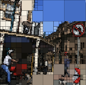
Original image transmitted in _MainTex :
The task of this shader is as follows:
- Determine whether image processing coordinates fall into the current block
- Find the average of 4 parental pixels and calculate the difference in color relative to the parent and the new color
- If we do not hit the current block, return the color that is already on the texture
For the zero level, the texture will be created as follows:
if (_Level == 0) { if (vo.uv.x < _sizeBlock.x) { float2 uv = float2(vo.uv.x / _sizeBlock.x, vo.uv.y); return tex2D(_MainTex, uv); } else { return fixed4(0,0,0,1); } } In proportion to the final size, we simply insert it and paint the remaining pixels in black.
For the remaining levels, you need to check the hit in the current block:
if (vo.uv.y >= _startBlock.y && vo.uv.y <= _endBlock.y && vo.uv.x >= _startBlock.x && vo.uv.x <= _endBlock.x) { To simplify the calculations, the color difference from the source will be considered only at the first level. The relative coordinates of the block are calculated as follows:
float2 uv = (vo.uv - _startBlock)/_szeBlock; float2 suv = float2(0.6666666667 * uv.x, uv.y); Now you need to take the four colors of the parent unit and calculate the average value plus the error.
fixed4 col1 = tex2D(_MainTex, suv); fixed4 col2 = tex2D(_MainTex, float2(min(suv.x + delta.x, _endBlock.x), suv.y)); fixed4 col3 = tex2D(_MainTex, float2(suv.x, min(suv.y - delta.y, _startBlock.y))); fixed4 col4 = tex2D(_MainTex, float2(suv.x, max(suv.y - delta.y, _startBlock.y))); col = (col1 + col2 + col3 + col4)/4; The error is calculated in a simple way: if the pixels differ in color, it will add (1 / n) to the error, where n is the number of color comparison combinations.
I will give an example of one combination:
float rgbError = 0; if (abs(DecodeFloatRGBA(col2) - DecodeFloatRGBA(col1)) > 0) { rgbError += 0.1666666667; } The result of the function is the average pixel color value, where the alpha channel is an error. This is the main simplification in my algorithm, since I didn’t have enough to calculate the color deviation through the histogram.
return fixed4(col.rgb, errorColor); At the other levels, the principle is similar, only the error will be calculated from the sum of the pixels of the parent block.
float errorColor = min((col1.a + col2.a + col3.a + col4.a), 1.0); As a result, walking through all levels, our tree will be formed. The next step is to display the tree on the screen, scaling it to fit the screen.
Creating an image from a tree
The task of this shader is as follows: determine an error for each level, and if it does not exceed the specified level, draw the required level with the color of the pixel in the tree. Shader parameters:
Properties { _MainTex ("Base (RGB)", 2D) = "white" {} _TileTex ("Tile (RGB)", 2D) = "white" {} } - _MainTex - texture of the created tree;
- _TileTex - texture with levels of the tree, to change the style of visualization;
 The quality of the final image depends on this texture, the background is transparent, and the figure inscribed in a square can be any.
The main function of the image output is as follows:
fixed4 getLevelColor(float level, float2 uv, float2 cellSize, float outSize) { float2 suv = float2(0.6666666667 + uv.x*cellSize.x, cellSize.y+uv.y*cellSize.y); fixed4 color = tex2D(_MainTex, suv); if (color.a > 0.59-(0.08*(9-level))) { return fixed4(0,0,0,0); } float2 scaledUV = frac(uv/outSize); float2 patternUV = float2(2*scaledUV.x*outSize, outSize+scaledUV.y*outSize); fixed4 tileColor = tex2D(_TileTex, patternUV) * fixed4(color.rgb, 1.0); fixed4 outcolor = lerp(tileColor, fixed4(0,0,0,1), 1 - tileColor.a); return fixed4(outcolor.rgb, 1); } Input parameters:
- cellSize - relative block size;
- outSize - relative size in the final image;
The idea is the following, for each pixel of the final image it is necessary to pass from the smallest block of the tree to the big one (bottom to top).
If the error is not more than the specified value (threshold):
if (color.a > 0.59-(0.08*(9-level))) // . Then we display the desired image from the _TileTex texture.
As a result, in order to run through the required levels, I had to strictly prescribe the conditions without any cycles.
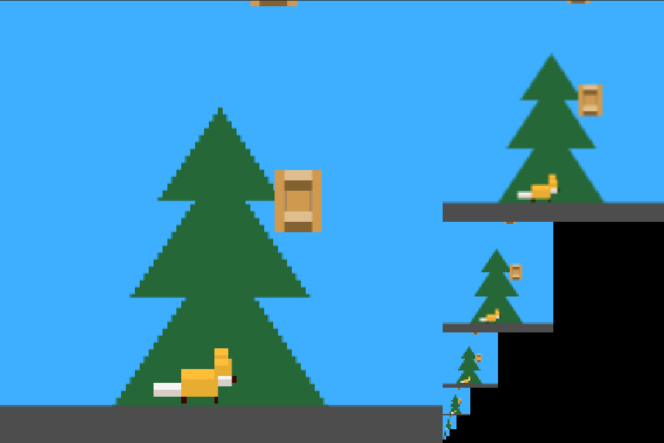
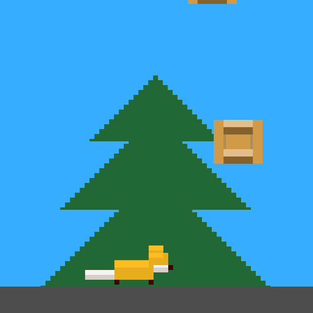
fixed4 value = float4(0,0,0,0); value = getLevelColor(7, vo.uv, float2(0.005208333333, 0.0078125), 0.5); if (value.a > 0) { return value; } value = getLevelColor(6, vo.uv, float2(0.01041666667, 0.015625), 0.25); if (value.a > 0) { return value; } value = getLevelColor(5, vo.uv, float2(0.02083333333, 0.03125), 0.125); if (value.a > 0) { return value; } value = getLevelColor(4, vo.uv, float2(0.04166666667, 0.0625), 0.0625); if (value.a > 0) { return value; } value = getLevelColor(3, vo.uv, float2(0.08333333333, 0.125), 0.03125); if (value.a > 0) { return value; } value = getLevelColor(2, vo.uv, float2(0.1666666667, 0.25), 0.015625); if (value.a > 0) { return value; } value = getLevelColor(1, vo.uv, float2(0.3333333333, 0.5), 0.0078125); if (value.a > 0) { return value; } return value; At the output we get the desired result:

Epilogue
As a result, we got a shader running on weak mobile devices with a frame rate of 25-30 or more. In this article I touched upon the image processing with “pure” colors, but you can go further and make the calculation of the color deviation error more complicated, then you can use this script in “noisy” images with a complex texture.
Example (from 44 seconds):
I wanted to apologize for the many magic numbers in the article. Thanks for attention!
Links to materials used:
- Effcient region segmentation on compressed images using quadtree and shading representation . Kuo-Liang Chunga, Hsu-Lien Huanga, Hsueh-I Lu
- RealTime QuadTree Analysis using HistoPyramids. Gernot Ziegler, Rouslan Dimitrovb, Christian Theobalta, Hans-Peter Seidela
a Max-Planck-Institut für Informatik, Stuhlsatzenhausweg 85, D-66123 Saarbrücken, Germany. bInternational University Bremen GmbH, Postfach 750561, D-28725 Bremen, Germany - HistoPyramid stream compaction and expansion. Christopher Dyken and Gernot Ziegler
- Quadtrees: Implementation . Herman tulleken
Source: https://habr.com/ru/post/280674/
All Articles