Math on the fingers: arduino of the brain or linear-quadratic regulator to control the electric motor
Problem statement: how to reach school-level conclusions with school knowledge
This article assumes that you have read my articles (well, or without it, you know) about the methods of least squares and about the linear-quadratic regulator.
As I said in previous articles, my familiar students want to build a reverse pendulum , but they were tired to select the PID controller coefficients, so I slowly look at what a linear-quadratic regulator is , well, and at the same time retell you what I read. The task for this article is to show how to implement a one-dimensional example from the article about a linear-quadratic regulator in hardware. Roughly speaking, I want to write a control for the servomotor: I have the current position of the drive axis and the current speed of its rotation, I want to stop it in a predetermined position. I tried to read a similar article on this topic, but I confess I did not understand anything, so I sat down to figure it out myself, preferably on fingers and without scary words like the Lagrange-Euler differential equations.
Continuing the worker exhibitionism, I introduce you to Bubble Bobble , who lives with my colleague in the office. He reviews articles for the SIGGRAPH conference.
')

Instructions for using my articles or why I am writing to habrakhabr
The instruction is strictly the same: let's be friendly to each other.
I am unable to write a coherent sequence of formulas without errors. Absolutely all my formulas are wrong. But personally, I am able to restore the correct one according to the wrong formula, since every character has its own semantics. If you manipulate mathematics as just a set of grammatical rules over some alphabet, you and I are not on the way. Personally, I can not operate with any concept if I do not have a “picture” in my head, some kind of intuition about the nature of the phenomenon under consideration. If you see my mistake, tell me about it, I will only be glad. Thank you in advance!
Expanded about this instruction
At the moment I have already written a half dozen articles on Habr, and according to the results I have to write a small lyrical digression about my goals. I am curious and read a lot, that is, I am constantly learning. In order to learn new things for me, I try to explain them to other people. As two classic quotes say:
Or the Russian version:
I came to Habrahabr for three things:
1. To share knowledge with people who know less than me.
2. This requires the structuring of information, so I can even better assimilate what I understood.
3. To get valuable comments from people who know more than me (by the way, most of the knowledge that I learned for this article was given to me by the distinguished Arastas ).
Each my article is a fruit of thinking for at least a few days, at least a few hours of writing the text and maybe a few hours of writing the source code, as far as possible I try to accompany my articles with programs. I feel bad about those who, right off the bat, tell me that I am an idiot. Thank you, I myself know this, there is no new information in this, but there is disrespect for my work. I highly welcome any comments containing constructive criticism. If I said nonsense, then write me where exactly and why. This will help me to correct the text, increasing my knowledge and knowledge of other readers. I also welcome any constructive questions and never treat arrogantly towards people who know less than me, which is why I demand a symmetrical attitude from those who know more than me.
I want to increase the number of people with good mood and high karma in Habré (besides, as we know, its hard deficit). Therefore, I generously distribute pluses to comments and to karma, but at the same time I am not ashamed to give out minuses, the latter concerns only arrogant and / or impolite people.
Look here to understand what exactly I would not want to see in the comments. I do not need cries about bydlohabr and statements that I am a moron. Yes, I personally do not know how to calculate the current-limiting resistor for the LED. I know how to limit his face value from above. Yes, I will take the LED resistance to zero and get a safe value for the resistor. And yes, I know that the LED can not glow for free. When it will be necessary, I will sort out the details, but for now, a rough estimate from above, which is guaranteed not to burn my fee, is fine. If you see an inaccuracy or just a mistake, correct it, all will benefit.
Stating it to another person.
* - Sherlock Holmes, Silver Blaze *
Or the Russian version:
Talk 2 teachers:
- Well, I got a group of stupid this year!
- Why?
- Imagine, explain the theorem - do not understand! I explain the second time - they do not understand !!! For the third time I explain. I already understood. But they do not understand ...
I came to Habrahabr for three things:
1. To share knowledge with people who know less than me.
2. This requires the structuring of information, so I can even better assimilate what I understood.
3. To get valuable comments from people who know more than me (by the way, most of the knowledge that I learned for this article was given to me by the distinguished Arastas ).
Each my article is a fruit of thinking for at least a few days, at least a few hours of writing the text and maybe a few hours of writing the source code, as far as possible I try to accompany my articles with programs. I feel bad about those who, right off the bat, tell me that I am an idiot. Thank you, I myself know this, there is no new information in this, but there is disrespect for my work. I highly welcome any comments containing constructive criticism. If I said nonsense, then write me where exactly and why. This will help me to correct the text, increasing my knowledge and knowledge of other readers. I also welcome any constructive questions and never treat arrogantly towards people who know less than me, which is why I demand a symmetrical attitude from those who know more than me.
I want to increase the number of people with good mood and high karma in Habré (besides, as we know, its hard deficit). Therefore, I generously distribute pluses to comments and to karma, but at the same time I am not ashamed to give out minuses, the latter concerns only arrogant and / or impolite people.
Look here to understand what exactly I would not want to see in the comments. I do not need cries about bydlohabr and statements that I am a moron. Yes, I personally do not know how to calculate the current-limiting resistor for the LED. I know how to limit his face value from above. Yes, I will take the LED resistance to zero and get a safe value for the resistor. And yes, I know that the LED can not glow for free. When it will be necessary, I will sort out the details, but for now, a rough estimate from above, which is guaranteed not to burn my fee, is fine. If you see an inaccuracy or just a mistake, correct it, all will benefit.
Available ironworks
An optical encoder is available (1000 pulses per revolution), an electric motor (750 rpm at 12V without load), a driver L6201 and atmega 328 (arduino nano).

Depending on the PWM signal that I apply to input L6201, it produces a different voltage to the motor. That is, my microcontroller can only control the voltage at the motor terminals.
Maxwell's equations on fingers or how a dc motor behaves
Most recently, I have already spoken about what Maxwell's equations are. Let's repeat: Maxwell's equations are four by the number of the following laws:
1. The law of Gauss, "on the fingers" is just a law of conservation: the energy is not taken from anywhere and does not go anywhere.
2. The law of Gauss for a magnetic field is the same, only for a magnetic, not an electric field.
3. Faraday's law: if we move magnets, they generate an electric field.
4. The law of Ampere: if we move an electric field, we generate a magnetic one.
The vector fields, which are the solution of these four equations, are called the electric field and the magnetic one. In the article on magnetic levitation, I was mainly interested in the laws of Gauss, in this article I am interested in the laws of Ampere and Faraday. How does a DC motor work in general? We pass current through the windings, it creates a magnetic field (see Ampere's law). This makes the rotor of our engine rotate.
Let's try to imagine how this engine works. We neglect everything that is possible (inductance, friction, etc.) and we recall only the course of the seventh-eighth grade of the school, namely, Ohm's law. So, the law of ohm says that voltage is the product of the strength of current and resistance (U = IR). The resistance of the motor windings is constant, therefore, up to a constant multiplier, the voltage on the winding and the current through it are one and the same. Further, Ampere's law says that the force applied to the rotor is proportional to the current to be passed, and therefore to our voltage. That is, if I live in my imaginary world, then by applying constant 12V to the motor windings, I create some constant force (moment).
But our engine is fully subject to the second law of Newton (F = ma). Thus, if I have a constant voltage on the motor winding, this entails a constant acceleration of the motor shaft (the mass does not change!). But this conclusion is starting to smell really bad, because if I have constant acceleration, then I can even spill the speed of light ...
Here it is time to remember that there is an option not to apply voltage to the engine, but to twist its shaft, on the contrary by removing the voltage from it (see bicycle generator). This is a consequence of Faraday's law: if we twist magnets, then it generates electromagnetic induction. "Voltage" (strictly speaking, EMF ) is directly proportional to engine speed: the faster we twist it, the more EMF (U = C * v, where U is voltage, C is some constant for our engine, and v is rotation speed shaft).
And in fact, what a hitch: if we still apply voltage to the engine, then the rotor turns (the Ampere's law), but at the same time it generates an EMF (Faraday's law) that fights against the applied voltage, reducing it! Thus, Ohm's law for the engine will look more like U - I * R - C * v = 0.
Ampere's law tells us that the current is proportional to the force created by the magnetic field. And Newton's second law says that force is proportional to acceleration (and acceleration is the derivative of speed over time!). Thus, Ohm's law for an engine can be written as u (t) - const1 * v '(t) - const2 * v (t) = 0. In the discrete world, the derivative v' (t) can be represented as v '(t) = v (t + 1) -v (t), so Ohm's law can be written as v (t + 1) = a * v (t) + b * u (t), where a and b are constants depending from the physical parameters of the engine and from the time step.
I applied four different DC voltages (24V, 18V, 12V, 6V) to the stopped motor and recorded the speed of movement of the carriage using an incremental encoder. Here are the tests:
This picture gives four different graphs (ugly, jagged) for four voltages:
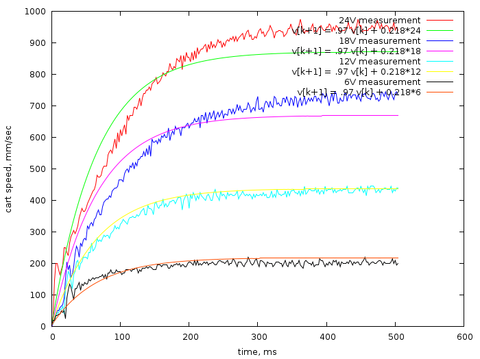
And also it gives a theoretical curve (I found a = 0.97, b = 0.218) for these voltages. Parameters a and b are found using an extremely blunt fitting code . Of course, in the real world, friction is non-zero, so my theoretical curve does not match all the measurements, but insofar as I assume that my carriage will move more often with a voltage around zero rather than around the maximum, the theoretical curve approximates better the movement at low voltages.
New formulation of linear-quadratic regulator
Attention: here it is assumed that you have read my article about linear-quadratic regulator well.
In it, our example was modeled by the following system of equations:

here x_k is the position of the carriage, v_k is its speed, and u_k is its acceleration. From the previous section, we know that the acceleration is very non-linearly dependent on the applied voltage, and this slightly annoys me, since the microcontroller is able to directly control only the voltage. But at the same time this dependence (with zero friction) is exponential, which very well falls within the framework of the linear transition system! Thus, I model the system as follows:
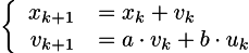
here x_k is the position of the carriage, v_k is its speed, and u_k is not the acceleration of the carriage, but the voltage that I apply to the terminals of the electric motor. For my particular engine, I found a = .97, b = .218.
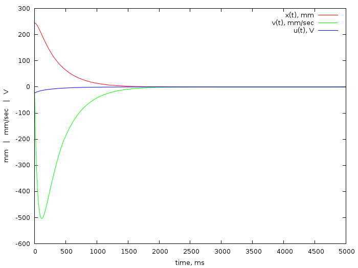
Here is the code that finds the coefficients of the dependence of the control variable (terminal voltage) on the state vector (position and speed of the carriage). My carriage can deviate as much as possible from the zero state to 245mm, so I set the initial zero speed and position to 245mm. The task is to stop the carriage in the zero position (rail center).
Lines 17-53 set the hard conditions of our system (initial and final conditions, linear transition of states), and lines 55-70 set the optimized function. The main task is the convergence of the position and velocity to zero (lines 56 and 61). I gradually increased the control limit (line 66), as long as the result did not fit into the physical parameters of the system (with these parameters, the voltage does not exceed 24V).
Here are the theoretical curves of the position, speed and voltage, which is necessary to achieve them:
Thus, the above code says that the voltage to be applied can be calculated as:

where x_k is the current position of the caret, and v_k is its speed.
Full code from the microcontroller
So, the latest formula is the main one for this article, here is my code for directly controlling the carriage.
Let me give him the main part:
void loop() { vi = xi-xi_1; int ui = 255.*(-0.000973669*xi -0.0563218*vi)/24.; xi_1 = xi; set_speed(ui); delay(2); } The calculation of the values of the eco-decoder (ISR function) deserves a separate small article, this is not the point at the moment. What is important is the loop () function. I consider the current speed as the difference in encoder position now and two milliseconds ago; then the current voltage ui is calculated using the formula just given. Everything! That's the whole linear quadratic regulator.
It would be nice to compare what we have done with theory, with what is obtained in practice. This picture gives a comparison:
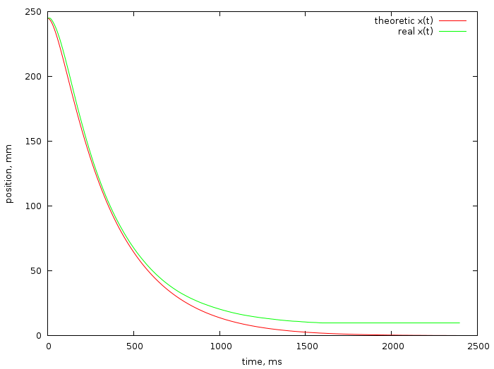
Thus, the real position of the carriage is slightly different from the theoretical one, I believe that this is due to unaccounted friction: the closer to zero, the lower the applied voltage, and once it can no longer deal with friction. The fight against this phenomenon will be the topic of one of the following articles. Stay tuned!
Good luck and be curious!
Source: https://habr.com/ru/post/280486/
All Articles