NetApp MetroCluster (MCC)
MetroCluster is a geo-distributed, fault-tolerant cluster built on the basis of NetApp FAS storage systems, such a cluster can be imagined as one storage system stretched across two sites, where in the event of a disaster at one of the sites there is always a complete copy of the data. MetroCluster is used to create highly accessible (HA) storage and services. Learn more about the MCC official documentation .
MetroCluster working on the old OS Data ONTAP 7-Mode (up to version 8.2.x) had the abbreviation "MC", and working on ClusteredONTAP (8.x and later), so that there is no confusion, it is accepted to call MetroCluster ClusteredONTAP (MCC).
An MCC may consist of two or more controllers. There are three MCC connection schemes:
')
The difference in these three options is essentially only in the network harness. The network binding affects two factors: the maximum possible distance over which the cluster can be stretched and the number of nodes in the cluster.
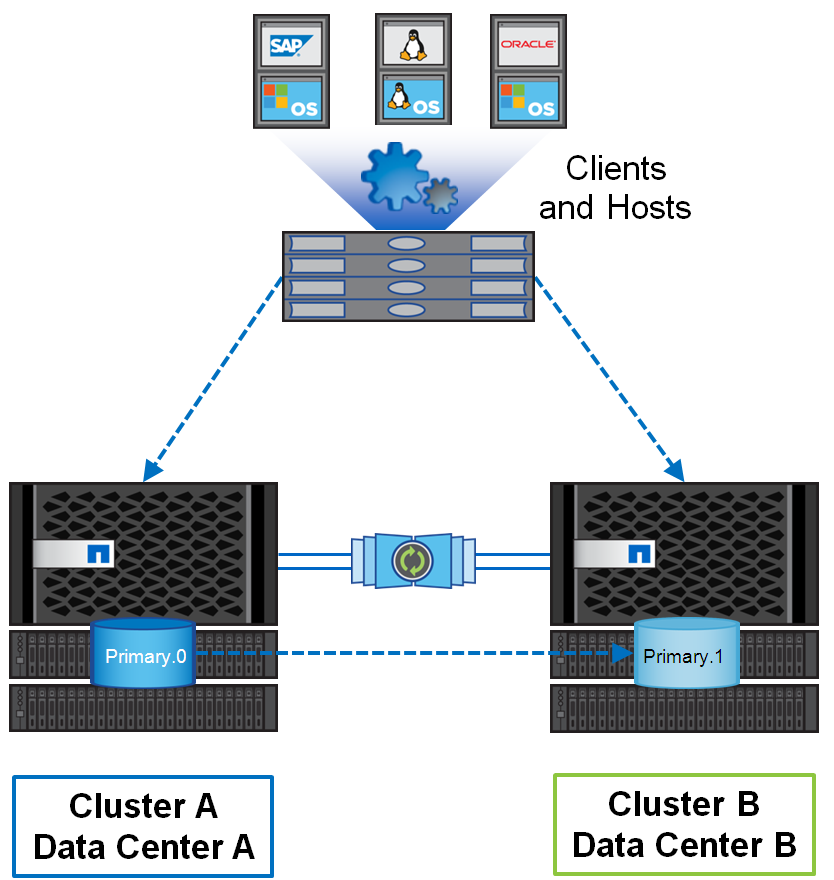
This configuration can consist of both two and 4 identical controllers. The dual node configuration (mcc-2n) can be converted to four node (mcc). In the two-channel configuration, one controller is located at each site, and if one controller comes out, the second at another site takes control, which is called a switchover . If there is more than one node on each site, and one node of the cluster fails, then a local HA failover occurs without switching to the second site. MetroCluster can stretch up to 300 km.
This is the most costly scheme of all connection options, as it requires:
Total between two sites requires at least 4 cores, plus Cluster peering.
Similar to the 4-node configuration of the Fabric-Attached MetroCluster, there is an eight-node configuration, which currently supports only NAS access protocols and ONTAP 9 firmware. Four node configurations can be updated to eight nodes. This configuration does not yet support SAN access protocols. In the eight-node configuration, 4 nodes are located on one site and 4 on the other. From a network point of view, nothing particularly changes, in a similar Fabric-Attached MetroCluster of 4 nodes: the number of FC switches on the back-end remains the same, only the number of necessary ports on each site for local switching increases, but there can be inter-site connections and inter-site ports as many. In such a scheme, cluster switches are required for 4xnn communication at each site, while 2 and 4 node configurations do not require the presence of cluster switches. The advantage of the 8-node configuration is the possibility of using two types of FAS systems in one cluster, for example, on one site you have FAS8040 (two nodes) and All Flash FAS 8060 (two nodes), on the other site we have exactly the same mirror configuration FAS8040 (two nodes) and All Flash FAS 8060 (two nodes). The data from one site on the FAS8040 system is replicated to the same FAS8040 system on another site and similarly for All Flash FAS 8060. The data within the site can be transparently migrated across these cluster nodes.
Can stretch to 500 meters and requires:
Total between two sites at least 4 + 8 = 12 lived, plus Cluster peering.
The cheapest option. Can stretch to 500 meters and requires:
Total between two sites at least 4 + 16 = 20 lived, plus Cluster peering.
Depending on the distance and connection speed, a different optical cable is used for direct-on Stretch MetroCluster configurations.
Usually, for each FAS cluster metro controller, a specialized expansion card is installed, on which FC ports operate in FC-VI mode. On some 4-port FC HBA boards for FAS controllers, it is allowed to use 2 ports for FC-VI and 2 others as target or initiator ports. On some FAS models, the ports onboard the motherboard can switch to FC-VI mode. Ports with the FC-VI role use the Fiber Channel protocol to mirror NVRAM content between cluster metro controllers.
There are two main approaches to data replication:
These are by definition two mutually exclusive approaches.
The advantage of “Approach B” is that there are no synchronization delays between the two sites. Due to circumstances not known to me, some storage vendors allow schemes in which Spit-Brain is possible. There are implementations in essence working on “Approach A”, but at the same time they emulate the ability to write on both sides at the same time, as if hiding the Active / Passive architecture, but the essence of such a scheme is that while one specific record transaction is not synchronized between two sites , it will not be confirmed, let's call it the “Hybrid approach”, it still contains the main data set and its mirror copy. In other words, this “Hybrid approach” is just a special case of “Approach A”, and should not be confused with “Approach B”, despite the deceptive similarities. The “hybrid approach” has the ability to access its data via a remote site, in such implementations, at first glance, there is a certain advantage over the classic version of “Approach A”, but in fact it does not change anything - the delay in synchronization of sites is as it is and it remains "Must Have" to protect against Spit-Brain. Let's look at the example in the figure below for all possible options for accessing data according to “Approach A” (including “Hybrid”).
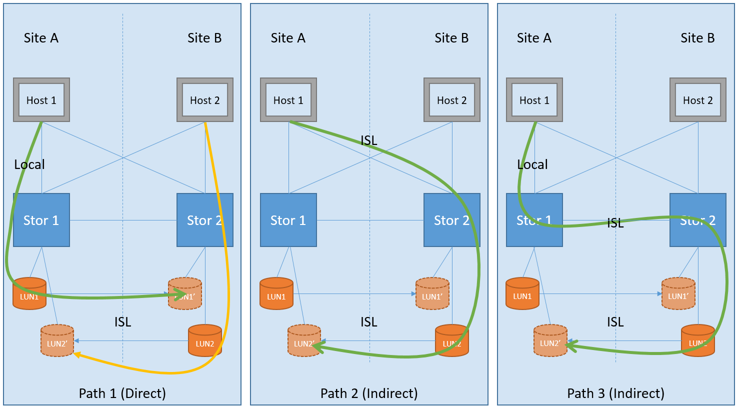
In the figure 3 variants of possible ways of accessing data are visualized. The first option (Path 1) is a classic implementation of the approach to protect against Split-Brain: data passes once a local path and once through a long ISL (Inter Switch Link) connection for mirroring. This option provides, as it were, an Active / Passive cluster robots mode, but each site has its own hosts, each of which accesses its local storage (Direct Path), where both sides of the cluster are utilized, thus forming the Active / Active configuration. In such an Active / Active configuration (with “Approach A”), the host will switch to the backup site only in the event of an accident, and when everything is restored, it will return to using the previous “direct” path. While the “Hybrid scheme” (with emulation of the ability to record through both sites at the same time) allows you to work on all 3 options of the paths. In the last two versions of Path 2 & Path 3, we have a completely opposite picture: the data crosses the long inter-site ISL (Indirect Path) communication channel twice, which increases the response speed. In the latter two versions of Path 2 & Path 3, there is no sense either in terms of fault tolerance, or in terms of performance, as compared to the first, and therefore they are not supported in the MetA Cluster NetApp, but work in Active / Active configuration mode (according to the classic Approach A ”), that is, using straight paths on each site, as depicted in Path 1.
As mentioned in the Active / Active section, the metro cluster is architecturally designed in such a way that local hosts work with the local half of the metro cluster. And only in the case when the whole site dies, the hosts switch to the second site. And what happens if both sites are alive, but the connection between them just disappeared? In the cluster metro architecture, everything is simple - the hosts continue to work, write and read, in their local halves, like nothing at all. Just at this moment the synchronization between the sites stops. As soon as the links are restored, both halves of the metro cluster will automatically begin to synchronize. In this situation, the data will be read from the main plex, and not as it usually happens through NVRAM, after both plexes become equal again, the mirroring will return to the replication mode based on NVRAM memory.
MCC is a completely symmetrical configuration: how many disks on one site are so many on another, what FAS systems are on one site, the same should be on another. Starting with the ONTAP 9 firmware version for FAS systems, it is allowed to have Unmirrored aggregates (pools). Thus, in the new firmware, the number of disks can now differ on two sites. Thus, for example, on one site there can be two aggregates, one of them is mirrored (on the remote site there is a full mirror on the types of disks, their speed, raid groups), the second unit, which is only on the first site, but it is not replicated on remote site.
It should be divided into two options for Active / Passive configurations:
Unmirrored aggregates allow you to create asymmetric configurations and, as an extreme, special case, the first option is Active / Passive configuration: when only one site is used for productive work, and the second accepts a synchronous replica and secures in case of failure of the main site. In this scheme, when a single controller fails, it immediately switches to a backup site.
The second version of the Active / Passive configuration is collected to save disks in a cluster of 4 or more nodes: only some of the controllers will serve clients, while controllers that are idle will wait patiently for the neighbor to die. This scheme allows not to switch between sites in the event of a single controller failure, but to perform a local ON takeover.
SyncMirror technology allows you to mirror data and can work in two modes:
The difference between the local SyncMirror and MCC SyncMirror is that in the first case the data is always mirrored from NVRAM within one controller and immediately into two plexes, it is sometimes used to protect against the failure of an entire shelf. And in the second case, NVRAM mirroring is performed between multiple controllers . NVRAM is mirrored across multiple controllers through dedicated FC-VI ports. MCC SyncMirror is used to protect against the failure of the whole site.
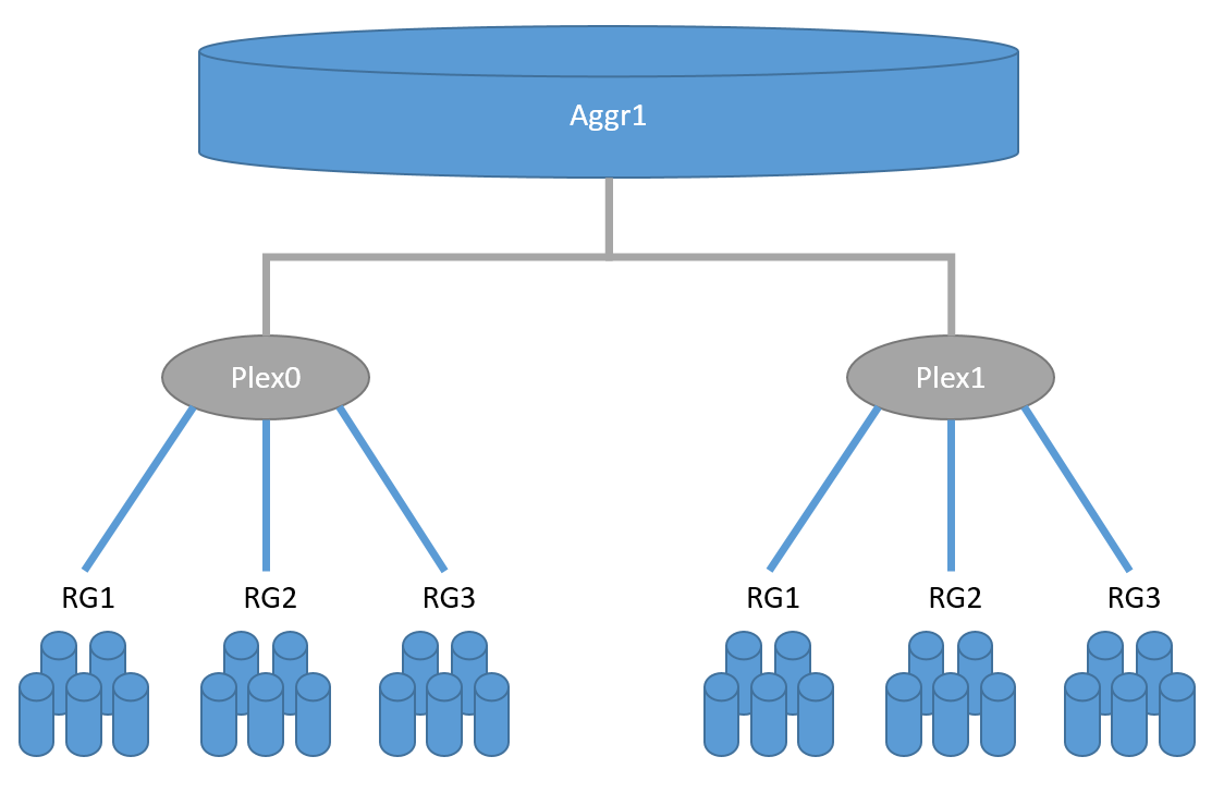
SyncMirror performs replication at RAID level, by analogy with mirrored RAID-60: there are two plexes, Plex0 (main dataset) and Plex1 (mirror), each plex can consist of one or several RAID-DP groups. Why "how-to"? Because these two plexes, they are visible as composite, mirror parts of one unit (pool), but in fact, in a normally working system, mirroring is performed at the NVRAM level of the controller. And as you may already know, WAFL, RAID-DP, NVRAM and NVLOG are all components of one whole disk subsystem architecture , and they can be quite conditionally separated from one another. An important detail of the SyncMirror technology is the need for full symmetry of the disks in two mirrored pools: the size, type, speed of the disks, the RAID groups must be completely the same. There are small exceptions to the rules, but for now I will not mention them in order not to mislead the reader.
Synchronous replication allows on the one hand to relieve the load on the disk subsystem, replicating only memory, on the other hand to solve Split-Brain and consistency problems (from the point of view of the WAFL structure on the storage system) you need to make sure that the data is written to the remote system: as a result “Synchronization”, in any storage systems, increases the speed of response for a time equal to the time of sending data to a remote site + the time to confirm this record.
Do not confuse
Sync Mirror replicates the contents of one plex to the second plex which constitute one aggregate: all its RAID groups, conditionally speaking “disk-based”, where the mirror should contain the same disks with the same number, volume, geometry and speed. The Sync Mirror MCC runs a replica of the NVLOG. In the case of local Sync Mirror, both plexes live and are served by the same controller. And in the case of the SyncMirror MCC, the two halves of the plex live, one on one controller, and the other on the remote. At one time, in normal operation of the storage system, only one plex is active and working, the second only stores a copy of the information.
Each unit can contain one or more Volum FlexVol (data container), each Volum is spread evenly across all the disks in the unit. Each volum is a separate WAFL structure. In the case of Snap Mirror, the replica runs at the WAFL level and can run on disks with a completely different geometry, number, and volume.
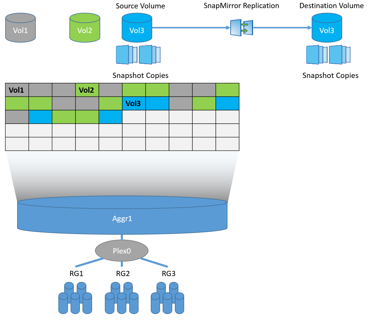
If you delve into technology, then in fact, both Snap and Sync Mirror use snapshots to replicate data, but in the case of Sync Mirror these are system snapshots based on the CP event (NVRAM / NVLOG) + snapshots at the aggregate level, and in the case of SnapMirror this FlexVol (WAFL) snapshots.
SnapMirror and SyncMirror can easily coexist with each other, so you can replicate data from / to the metro cluster from another storage system with ONTAP firmware.
In order to protect data from Split-Brain, the data that is written to enter NVRAM as logs (NVLOG) and into system memory. Record confirmation to the host will come only after they get into NVRAM of one local controller, its neighbor (if the MCC consists of 4 nodes) and one remote neighbor. Synchronization between local controllers is performed via HA interconnect (this is usually an internal bus or sometimes it is an external connection), and synchronization to a remote node is performed via FC-IV ports. The local partner has only a copy of NVLOG, it does not create a full copy of the data, because it already sees disks with this data of its ON neighbor. A remote DR partner has a copy of NVLOG and has a complete copy of all data (in Plex 1) on its own disks. This scheme allows you to switch within the site if the second HA controller of the pair has survived or switch to the second site if all the local storage nodes have failed. switching to the second site takes a couple of seconds.
The picture shows a diagram for a four-node metro cluster. The two-node scheme is similar, but has no local ON partner. The eight-node scheme is the same two four node schemes: i.e. In this configuration, the NVRAM replica runs within these 4 nodes, and the combination of two such four node configurations allows you to transparently move data between the metro cluster nodes within each site.
NVRAM complements the SyncMirror technology: after the data is received in NVRAM of the remote storage, the record confirmation is immediately received, ie the RAID comes to a fully synchronous state on the second plex with a delay, without compromising the consistency of the mirror copy - this allows the response speed to be significantly accelerated when mirroring the halves of the metro cluster .
In order to perform automatic switching between two sites, human intervention is necessary, or a third node, an impartial and all-seeing arbiter who can decide which of the sites should survive after the accident, is called a TieBreaker. TieBreaker is either free software from NetApp for Windows Server or specialized hardware ClusterLion .
If TieBreaker is not installed, you can switch between sites manually from the free utility OnCommand Unified Manager (OCUM) or from the command line using the commands metrocluster switchover .
MCC supports All Flash FAS systems for Fabric-Attached and Bridge-Attached Stretch MetroCluster configurations, it is recommended to use ATTO 7500N FibreBridge bridges.
The virtualization technology FlexArray allows you to use third-party storage systems as a back-end, connecting them using the FCP protocol. You may not have native shelves with NetApp disk shelves. Third-party storage systems can be connected through the same FC factories as for FC-VI connectivity; this can save a lot of money both on the fact that the Fabric-Attached MetroCluster scheme eliminates the need for FC-SAS bridges, and on the fact that existing ones can be disposed of. allowing you to save investments by disposing of old storage systems. FlexArray requires that the storage system be in the compatibility matrix .
VMware can use with MCC to provide HA based on NetApp hardware replication. As with SRM / SRA, this is a plugin for vCenter that can interact with MetroCluster TieBreaker to provide automatic switching in the event of a crash.
VVOL technology is supported with vMSC.
The MCC technology is designed to create highly available storage and highly available services on top of it. Using hardware replication SyncMirror allows you to replicate very large critical corporate infrastructures and, in the event of a disaster, automatically or manually switch between sites while protecting against Split-Brain. The MCC is designed in such a way that for end hosts it looks like a single device, and the switch for the host is performed at the network fault tolerance level. This allows the integration of the MCC with almost any solution.
This may contain links to Habra articles that will be published later.
I ask to send messages on errors in the text to the LAN .
Comments, additions and questions on the article on the contrary, please in the comments.
MetroCluster working on the old OS Data ONTAP 7-Mode (up to version 8.2.x) had the abbreviation "MC", and working on ClusteredONTAP (8.x and later), so that there is no confusion, it is accepted to call MetroCluster ClusteredONTAP (MCC).
An MCC may consist of two or more controllers. There are three MCC connection schemes:
')
- Fabric-Attached MetroCluster (FCM-MCC)
- Bridge-Attached Stretch MetroCluster
- Stretch MetroCluster
The difference in these three options is essentially only in the network harness. The network binding affects two factors: the maximum possible distance over which the cluster can be stretched and the number of nodes in the cluster.
Fabric-Attached MetroCluster
This configuration can consist of both two and 4 identical controllers. The dual node configuration (mcc-2n) can be converted to four node (mcc). In the two-channel configuration, one controller is located at each site, and if one controller comes out, the second at another site takes control, which is called a switchover . If there is more than one node on each site, and one node of the cluster fails, then a local HA failover occurs without switching to the second site. MetroCluster can stretch up to 300 km.
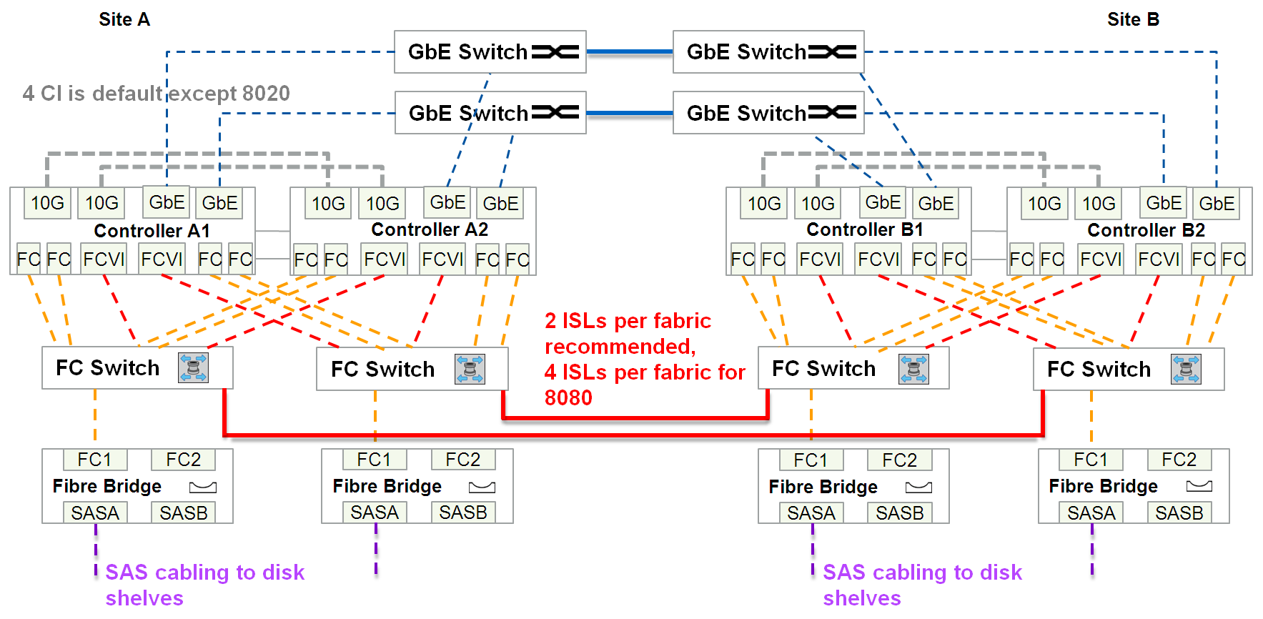
This is the most costly scheme of all connection options, as it requires:
- Double the number of shelves
- One or two IP channels for Cluster peering network
- Additional SAN switches on back-end (not to be confused with switches for connecting storage systems and hosts)
- Additional SAS-FC bridges
- FC-VI ports
- Possible xWDM multiplexers
- And at least 2 ISL long-wave FC SFP + links (4 cores: 2x RX, 2x TX). Those. “dark optics” are brought to the storage system (in the intervals there can be only xWDM, without any switches), these links are dedicated exclusively to the tasks of storage replication (FC-VI & back-end connections)
Total between two sites requires at least 4 cores, plus Cluster peering.
8-Node MCC
Similar to the 4-node configuration of the Fabric-Attached MetroCluster, there is an eight-node configuration, which currently supports only NAS access protocols and ONTAP 9 firmware. Four node configurations can be updated to eight nodes. This configuration does not yet support SAN access protocols. In the eight-node configuration, 4 nodes are located on one site and 4 on the other. From a network point of view, nothing particularly changes, in a similar Fabric-Attached MetroCluster of 4 nodes: the number of FC switches on the back-end remains the same, only the number of necessary ports on each site for local switching increases, but there can be inter-site connections and inter-site ports as many. In such a scheme, cluster switches are required for 4xnn communication at each site, while 2 and 4 node configurations do not require the presence of cluster switches. The advantage of the 8-node configuration is the possibility of using two types of FAS systems in one cluster, for example, on one site you have FAS8040 (two nodes) and All Flash FAS 8060 (two nodes), on the other site we have exactly the same mirror configuration FAS8040 (two nodes) and All Flash FAS 8060 (two nodes). The data from one site on the FAS8040 system is replicated to the same FAS8040 system on another site and similarly for All Flash FAS 8060. The data within the site can be transparently migrated across these cluster nodes.
Bridge-Attached Stretch MetroCluster
Can stretch to 500 meters and requires:
- Double the number of shelves
- One or two IP channels for Cluster peering network
- Additional SAS-FC bridges
- FC-VI ports
- at least two links (4 cores: 2x RX, 2x TX) of dark optics dedicated exclusively for the connection of storage controllers (FC-VI)
- And at least four links (total 4x2 = 8 cores) of dark optics, allocated exclusively for back-end communications
Total between two sites at least 4 + 8 = 12 lived, plus Cluster peering.
Direct Power Stretch MetroCluster
The cheapest option. Can stretch to 500 meters and requires:
- Double the number of shelves
- One or two IP channels for Cluster peering network
- FC-VI ports
- at least two links (4 cores: 2x RX, 2x TX) of dark optics dedicated exclusively for the connection of storage controllers (FC-VI)
- And at least two 4 channel (for each channel 2 lived: RX and TX) cable (total 2x8 = 16 lived) of dark optics allocated exclusively for replication tasks for access to each shelf in two ways.
- For back-end connectivity of shelves, a special 4 channel (for each channel 2 lived: RX and TX) optical SAS connector and optical patch panel are used
Total between two sites at least 4 + 16 = 20 lived, plus Cluster peering.
Optical cable for Stretch MetroCluster
Depending on the distance and connection speed, a different optical cable is used for direct-on Stretch MetroCluster configurations.
| Speed (Gbps) | Maximum distance (m) | |||
|---|---|---|---|---|
| 16Gbps SW SFP | 16Gbps LW SFP | |||
| OM2 | OM3 | OM3 + / OM4 | Single-Mode (SM) Fiber | |
| 2 | N / A | N / A | N / A | N / A |
| four | 150 | 270 | 270 | 500 |
| eight | 50 | 150 | 170 | 500 |
| sixteen | 35 | 100 | 125 | 500 |
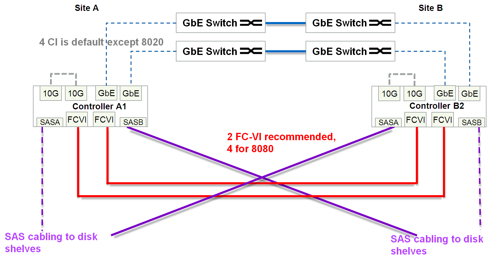
FC-VI ports
Usually, for each FAS cluster metro controller, a specialized expansion card is installed, on which FC ports operate in FC-VI mode. On some 4-port FC HBA boards for FAS controllers, it is allowed to use 2 ports for FC-VI and 2 others as target or initiator ports. On some FAS models, the ports onboard the motherboard can switch to FC-VI mode. Ports with the FC-VI role use the Fiber Channel protocol to mirror NVRAM content between cluster metro controllers.
Active / Active
There are two main approaches to data replication:
- “Approach A”: Split-Brain Protection Provided
- “Approach B”: In which there is a possibility of access (reading and writing) to all data through all sites
These are by definition two mutually exclusive approaches.
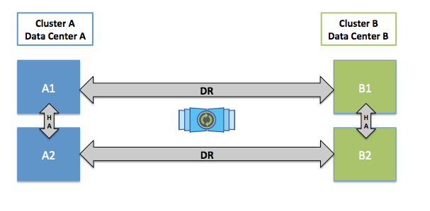
The advantage of “Approach B” is that there are no synchronization delays between the two sites. Due to circumstances not known to me, some storage vendors allow schemes in which Spit-Brain is possible. There are implementations in essence working on “Approach A”, but at the same time they emulate the ability to write on both sides at the same time, as if hiding the Active / Passive architecture, but the essence of such a scheme is that while one specific record transaction is not synchronized between two sites , it will not be confirmed, let's call it the “Hybrid approach”, it still contains the main data set and its mirror copy. In other words, this “Hybrid approach” is just a special case of “Approach A”, and should not be confused with “Approach B”, despite the deceptive similarities. The “hybrid approach” has the ability to access its data via a remote site, in such implementations, at first glance, there is a certain advantage over the classic version of “Approach A”, but in fact it does not change anything - the delay in synchronization of sites is as it is and it remains "Must Have" to protect against Spit-Brain. Let's look at the example in the figure below for all possible options for accessing data according to “Approach A” (including “Hybrid”).
In the figure 3 variants of possible ways of accessing data are visualized. The first option (Path 1) is a classic implementation of the approach to protect against Split-Brain: data passes once a local path and once through a long ISL (Inter Switch Link) connection for mirroring. This option provides, as it were, an Active / Passive cluster robots mode, but each site has its own hosts, each of which accesses its local storage (Direct Path), where both sides of the cluster are utilized, thus forming the Active / Active configuration. In such an Active / Active configuration (with “Approach A”), the host will switch to the backup site only in the event of an accident, and when everything is restored, it will return to using the previous “direct” path. While the “Hybrid scheme” (with emulation of the ability to record through both sites at the same time) allows you to work on all 3 options of the paths. In the last two versions of Path 2 & Path 3, we have a completely opposite picture: the data crosses the long inter-site ISL (Indirect Path) communication channel twice, which increases the response speed. In the latter two versions of Path 2 & Path 3, there is no sense either in terms of fault tolerance, or in terms of performance, as compared to the first, and therefore they are not supported in the MetA Cluster NetApp, but work in Active / Active configuration mode (according to the classic Approach A ”), that is, using straight paths on each site, as depicted in Path 1.
Split-brain
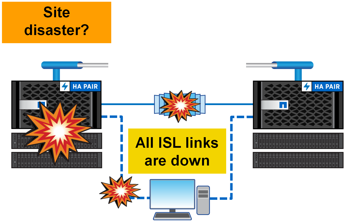
As mentioned in the Active / Active section, the metro cluster is architecturally designed in such a way that local hosts work with the local half of the metro cluster. And only in the case when the whole site dies, the hosts switch to the second site. And what happens if both sites are alive, but the connection between them just disappeared? In the cluster metro architecture, everything is simple - the hosts continue to work, write and read, in their local halves, like nothing at all. Just at this moment the synchronization between the sites stops. As soon as the links are restored, both halves of the metro cluster will automatically begin to synchronize. In this situation, the data will be read from the main plex, and not as it usually happens through NVRAM, after both plexes become equal again, the mirroring will return to the replication mode based on NVRAM memory.
Active / Passive and Unmirrored Aggregates
MCC is a completely symmetrical configuration: how many disks on one site are so many on another, what FAS systems are on one site, the same should be on another. Starting with the ONTAP 9 firmware version for FAS systems, it is allowed to have Unmirrored aggregates (pools). Thus, in the new firmware, the number of disks can now differ on two sites. Thus, for example, on one site there can be two aggregates, one of them is mirrored (on the remote site there is a full mirror on the types of disks, their speed, raid groups), the second unit, which is only on the first site, but it is not replicated on remote site.
It should be divided into two options for Active / Passive configurations:
- First option. When only one main site is used, and the second takes a replica and lives for safety in case the main site is turned off
- The second option. When there are 4 or more nodes in the cluster and not all controllers are used at each site
Unmirrored aggregates allow you to create asymmetric configurations and, as an extreme, special case, the first option is Active / Passive configuration: when only one site is used for productive work, and the second accepts a synchronous replica and secures in case of failure of the main site. In this scheme, when a single controller fails, it immediately switches to a backup site.
The second version of the Active / Passive configuration is collected to save disks in a cluster of 4 or more nodes: only some of the controllers will serve clients, while controllers that are idle will wait patiently for the neighbor to die. This scheme allows not to switch between sites in the event of a single controller failure, but to perform a local ON takeover.
SyncMirror - Synchronous Replication
SyncMirror technology allows you to mirror data and can work in two modes:
- Local SyncMirror
- MetroCluster SyncMirror
The difference between the local SyncMirror and MCC SyncMirror is that in the first case the data is always mirrored from NVRAM within one controller and immediately into two plexes, it is sometimes used to protect against the failure of an entire shelf. And in the second case, NVRAM mirroring is performed between multiple controllers . NVRAM is mirrored across multiple controllers through dedicated FC-VI ports. MCC SyncMirror is used to protect against the failure of the whole site.
SyncMirror performs replication at RAID level, by analogy with mirrored RAID-60: there are two plexes, Plex0 (main dataset) and Plex1 (mirror), each plex can consist of one or several RAID-DP groups. Why "how-to"? Because these two plexes, they are visible as composite, mirror parts of one unit (pool), but in fact, in a normally working system, mirroring is performed at the NVRAM level of the controller. And as you may already know, WAFL, RAID-DP, NVRAM and NVLOG are all components of one whole disk subsystem architecture , and they can be quite conditionally separated from one another. An important detail of the SyncMirror technology is the need for full symmetry of the disks in two mirrored pools: the size, type, speed of the disks, the RAID groups must be completely the same. There are small exceptions to the rules, but for now I will not mention them in order not to mislead the reader.
Synchronous replication allows on the one hand to relieve the load on the disk subsystem, replicating only memory, on the other hand to solve Split-Brain and consistency problems (from the point of view of the WAFL structure on the storage system) you need to make sure that the data is written to the remote system: as a result “Synchronization”, in any storage systems, increases the speed of response for a time equal to the time of sending data to a remote site + the time to confirm this record.
SnapMirror vs SyncMirror
Do not confuse
- Sync mirror
- and snap mirror
Sync Mirror replicates the contents of one plex to the second plex which constitute one aggregate: all its RAID groups, conditionally speaking “disk-based”, where the mirror should contain the same disks with the same number, volume, geometry and speed. The Sync Mirror MCC runs a replica of the NVLOG. In the case of local Sync Mirror, both plexes live and are served by the same controller. And in the case of the SyncMirror MCC, the two halves of the plex live, one on one controller, and the other on the remote. At one time, in normal operation of the storage system, only one plex is active and working, the second only stores a copy of the information.
Each unit can contain one or more Volum FlexVol (data container), each Volum is spread evenly across all the disks in the unit. Each volum is a separate WAFL structure. In the case of Snap Mirror, the replica runs at the WAFL level and can run on disks with a completely different geometry, number, and volume.
If you delve into technology, then in fact, both Snap and Sync Mirror use snapshots to replicate data, but in the case of Sync Mirror these are system snapshots based on the CP event (NVRAM / NVLOG) + snapshots at the aggregate level, and in the case of SnapMirror this FlexVol (WAFL) snapshots.
SnapMirror and SyncMirror can easily coexist with each other, so you can replicate data from / to the metro cluster from another storage system with ONTAP firmware.
Memory and NVRAM
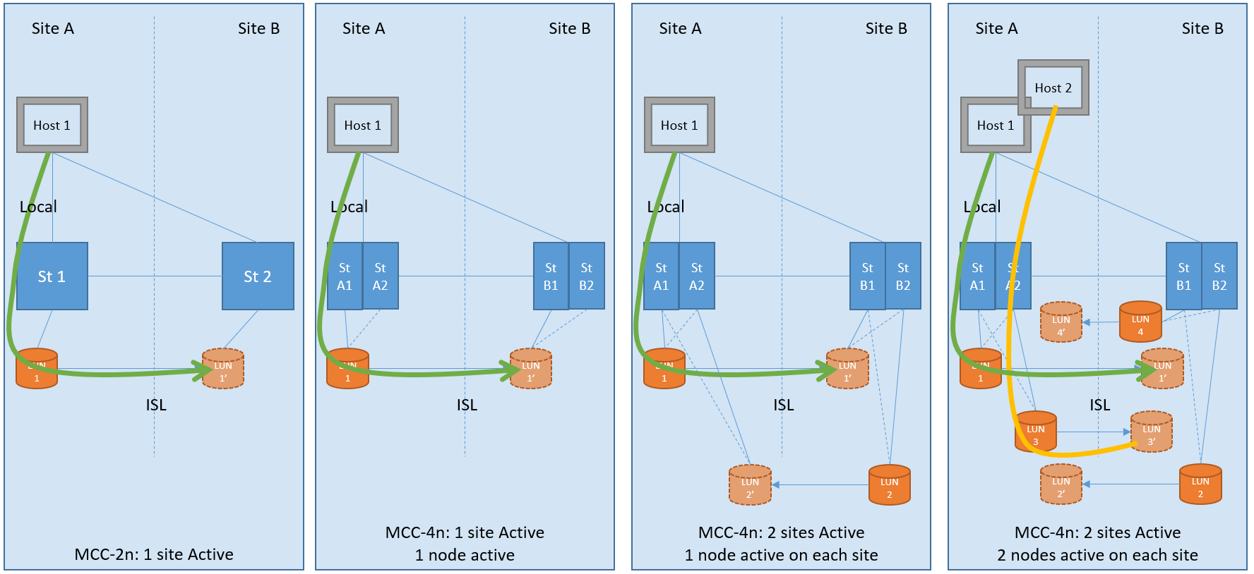
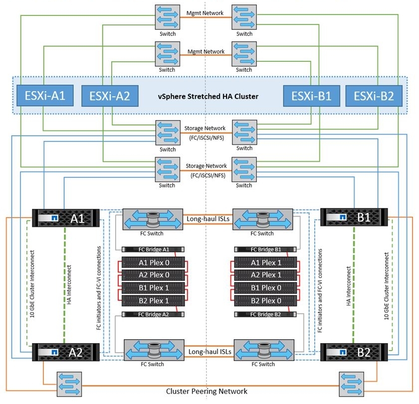
In order to protect data from Split-Brain, the data that is written to enter NVRAM as logs (NVLOG) and into system memory. Record confirmation to the host will come only after they get into NVRAM of one local controller, its neighbor (if the MCC consists of 4 nodes) and one remote neighbor. Synchronization between local controllers is performed via HA interconnect (this is usually an internal bus or sometimes it is an external connection), and synchronization to a remote node is performed via FC-IV ports. The local partner has only a copy of NVLOG, it does not create a full copy of the data, because it already sees disks with this data of its ON neighbor. A remote DR partner has a copy of NVLOG and has a complete copy of all data (in Plex 1) on its own disks. This scheme allows you to switch within the site if the second HA controller of the pair has survived or switch to the second site if all the local storage nodes have failed. switching to the second site takes a couple of seconds.
The picture shows a diagram for a four-node metro cluster. The two-node scheme is similar, but has no local ON partner. The eight-node scheme is the same two four node schemes: i.e. In this configuration, the NVRAM replica runs within these 4 nodes, and the combination of two such four node configurations allows you to transparently move data between the metro cluster nodes within each site.
NVRAM complements the SyncMirror technology: after the data is received in NVRAM of the remote storage, the record confirmation is immediately received, ie the RAID comes to a fully synchronous state on the second plex with a delay, without compromising the consistency of the mirror copy - this allows the response speed to be significantly accelerated when mirroring the halves of the metro cluster .
Tie breaker witness
In order to perform automatic switching between two sites, human intervention is necessary, or a third node, an impartial and all-seeing arbiter who can decide which of the sites should survive after the accident, is called a TieBreaker. TieBreaker is either free software from NetApp for Windows Server or specialized hardware ClusterLion .
OnCommand Unified Manager (OCUM)
If TieBreaker is not installed, you can switch between sites manually from the free utility OnCommand Unified Manager (OCUM) or from the command line using the commands metrocluster switchover .
All-Flash
MCC supports All Flash FAS systems for Fabric-Attached and Bridge-Attached Stretch MetroCluster configurations, it is recommended to use ATTO 7500N FibreBridge bridges.
FlexArray
The virtualization technology FlexArray allows you to use third-party storage systems as a back-end, connecting them using the FCP protocol. You may not have native shelves with NetApp disk shelves. Third-party storage systems can be connected through the same FC factories as for FC-VI connectivity; this can save a lot of money both on the fact that the Fabric-Attached MetroCluster scheme eliminates the need for FC-SAS bridges, and on the fact that existing ones can be disposed of. allowing you to save investments by disposing of old storage systems. FlexArray requires that the storage system be in the compatibility matrix .
VMware vSphere Metro Storage Cluster
VMware can use with MCC to provide HA based on NetApp hardware replication. As with SRM / SRA, this is a plugin for vCenter that can interact with MetroCluster TieBreaker to provide automatic switching in the event of a crash.
VMware VVOL
VVOL technology is supported with vMSC.
findings
The MCC technology is designed to create highly available storage and highly available services on top of it. Using hardware replication SyncMirror allows you to replicate very large critical corporate infrastructures and, in the event of a disaster, automatically or manually switch between sites while protecting against Split-Brain. The MCC is designed in such a way that for end hosts it looks like a single device, and the switch for the host is performed at the network fault tolerance level. This allows the integration of the MCC with almost any solution.
This may contain links to Habra articles that will be published later.
I ask to send messages on errors in the text to the LAN .
Comments, additions and questions on the article on the contrary, please in the comments.
Source: https://habr.com/ru/post/279989/
All Articles