Ferroelectric (ferroelectric) memory and electronic ink - the perfect combination for battery power
When Texas Instruments equipped its well-known low-power MSP430 series with ferroelectric memory , it became even easier and more pleasant to work with it, because such memory combines the advantages of flash and RAM. A new pad with a segment indicator - just a ready platform for some sort of home automation. And what if you need a graphic display? Here electronic ink comes to the rescue, because they consume energy only when upgraded and are able to please for years with a beautiful contrast picture, feeding on one set of batteries. If you are interested in the experience of programming such a device - welcome to Cat. I will talk about what ferroelectric memory is and why it is needed, how to achieve the lowest possible power consumption and get a beautiful picture on e-paper and use the code written under arduino on Texas.
I started the study of the MSP430 series with the first MSP-EXP430G2 first 'popular' lapse board . Therefore, when the MSP-EXP430FR4133 and MSP-EXP430FR6989 lunches withpearl buttons with ferroelectric memory and segment LCD appeared on sale, and for almost the same price, I immediately got the idea to make some nice gadget on them.
')
The ferroelectric memory is based on a special material - lead zirconate titanate (PZT). It is a ferroelectric, that is, capable of spontaneous polarization. In the structure of this material there are positively charged atoms, 'trapped' in the cell of a negatively charged crystal lattice, and capable of shifting relative to the center of this cell. This displacement occurs under the action of an electric field and leads to an electric charge flowing in the external circuit. After removal of the electric field, the cell remains polarized, which allows using this effect to store binary information.
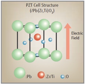
Zeros and ones are encoded by polarization PZT in opposite directions. The only problem is that reading is possible only when the polarization direction is changed, since this is the only way to get a current pulse in an external circuit. That is, reading is associated with erasing previously recorded information, and it must be immediately restored. This disadvantage is compensated by the fact that it takes very little time to change the direction of polarization — on the order of a nanosecond. So the recording is much faster than in traditional flash memory, and does not require pre-erasing of blocks. In fact, you can work with such memory in the same way as with operational memory, and at the same time it retains its contents after turning off the power. Imagine that we need a buffer to store the settings or to fit an array of data that does not fit into the RAM. We can implement it as follows:
Much more convenient than messing with erasing flash blocks is it?
The first thing I did when I took the MSP-EXP430FR6989 board into my hands was measuring the current consumed by it and was slightly surprised, since the current was about 80 microamps with the processor stopped. I wrote a simple two-line program whose meaning comes down to stopping the processor:
Of course, leaving the I / O ports uninitialized incorrectly. By default, they operate on input, and the floating potential of the input leads to the flow of through-current through the transistors of the input buffer. It is necessary either to program the ports for output, or to connect pull-up resistors. I implemented the second option, fearing for the peripherals connected to the processor:
The current consumption has decreased to 40 microamperes, which is still 10 times more than the result, which was demonstrated by MSP430 processors of the previous generation. What is the matter? It turns out that in the new processors an advanced control circuit for the quality of the clock is implemented, which with particular predilection monitors the quartz oscillators. It is the external crystal oscillator that is selected by default as the source of the low-frequency clock. If it is not connected, or you have not configured the feet to which it is connected, the error flag of the low-frequency clock is set, after which the backup internal RC frequency generator 5MHz is started, this frequency is divided into 128 and used as a low-frequency clock. It is this generator that consumes 40 microamps. The paradox of this obsessive concern for the quality of the shred is that the low-frequency shred in this situation is not used at all!
There are 2 ways to deal with this phenomenon. First, you can use the internal RC low frequency clock generator. The code for this case is shown below:
If you care about the accuracy of the clock frequency (for example, for a clock), then this method is not suitable. You really need a low-frequency crystal oscillator. You can add a loop that will wait for the stabilization of the clock and clear the error flags, without having forgotten to pre-configure the feet to which the quartz is connected:
The problem with this decision is that if during the operation due to electromagnetic interference, for example, a low-frequency generator error occurs again, it is not processed in any way, as a result of which your clock will go wrong and will actively eat the battery. An alternative option that always works is to handle errors in the interrupt:
Now the board in the stop mode of the processor consumes 0.9 microamperes with a quartz oscillator and 0.6 without it, which is almost an order of magnitude better than the result of the previous generation MSP430!
Managing the segmented LCD on board thanks to the libraries provided by TI is not a problem, but it also brought several surprises. First, the LCD initialization code provided by TI initializes more segments than they really are. As a result, an alternating voltage with an average value close to half the supply voltage was present on many of the expansion connector pins. Secondly, LCD consumes unreasonably a lot - about 40 microamps. But as you know, so that a cow eats less, it only needs to be fed less often. Reducing the frequency of the LCD clock signal reduced the current consumption to 6.5 microamperes.
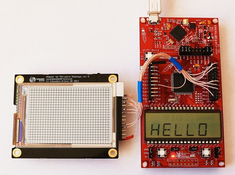
An electronic ink screen was chosen as a graphic display. On the manufacturer's page you will find a lot of libraries, but as usual, not the ones you need. Libraries provided by the screen maker generally make a heavy impression, since they are made with the expectation of ease of writing and are a multi-layered cake whose performance will be acceptable only on something very fast, like RaspberryPi. There was, however, an adapted version of the Arduino, where the whole layer cake was tamped into one module. It was decided to start with it in the absence of the best and unwillingness to reinvent the next bicycle. At first, I just implemented access functions to ports like digitalWrite / digitalRead in the most general form. When instead of the expected picture I saw, muddy divorces slowly appearing on the screen, my first desire was to send the screen back. However, according to common sense, I decided that something was wrong here. At first, I accelerated the process of developing turbid divorces, slightly optimizing the code - I made all the I / O functions inline. At the same time, I simply relied on the fact that I would have all the necessary legs on one port, so that the Arduin’s leg number is the corresponding bit. Working with SPI also became inline, the result can be seen here . Along the way, I was surprised to learn that there can be only one port in the Arduin SPI - hence the last 2 lines in the file using the link above. The optimized version of the painted divorce much faster, and they did not look as dirty as before. Then I went even further and increased the processor clock speed to 8MHz - the picture became almost perfect. Apparently the display controller has neither its own memory nor the clock generator, but simply uses the input signals to generate the voltages it needs. Accordingly, if the data transfer is too slow, these supply voltages are less than needed for the update. The update process is illustrated in the following video.
The last thing you need to do with the screen, if you are going to power it from the battery, is to remove the extra parts installed on the display controller board just in case as a bonus. The temperature sensor U6 consumes 100 microamps. This current can be reduced only by sending an off command to it, but we are not going to connect it to the I2C port just for the sake of it. Much easier to cut the power cord. U5 flash memory consumes another 5 microamperes, I coped with it, having completely soldered it. Now the entire system with a working real-time clock consumes 10 microamps. The screen when updating consumes 10 milliamps for 5 seconds. With a battery capacity of 1 A * hour (typical value for AA format), it will last for 10 years, and once every hour and a half, the screen is updated for 5 years. It remains only to draw something meaningful on it, but more on that next time.
Lies here . IAR Embedded Workbench for MSP430 version 6.40.1 was used for compilation. No additional libraries required.
I started the study of the MSP430 series with the first MSP-EXP430G2 first 'popular' lapse board . Therefore, when the MSP-EXP430FR4133 and MSP-EXP430FR6989 lunches with
')
What is good ferroelectric memory
The ferroelectric memory is based on a special material - lead zirconate titanate (PZT). It is a ferroelectric, that is, capable of spontaneous polarization. In the structure of this material there are positively charged atoms, 'trapped' in the cell of a negatively charged crystal lattice, and capable of shifting relative to the center of this cell. This displacement occurs under the action of an electric field and leads to an electric charge flowing in the external circuit. After removal of the electric field, the cell remains polarized, which allows using this effect to store binary information.
Zeros and ones are encoded by polarization PZT in opposite directions. The only problem is that reading is possible only when the polarization direction is changed, since this is the only way to get a current pulse in an external circuit. That is, reading is associated with erasing previously recorded information, and it must be immediately restored. This disadvantage is compensated by the fact that it takes very little time to change the direction of polarization — on the order of a nanosecond. So the recording is much faster than in traditional flash memory, and does not require pre-erasing of blocks. In fact, you can work with such memory in the same way as with operational memory, and at the same time it retains its contents after turning off the power. Imagine that we need a buffer to store the settings or to fit an array of data that does not fit into the RAM. We can implement it as follows:
const uint8_t buff_holder[BUFF_SZ]; // FRAM uint8_t* buff = (uint8_t*)buff_holder; // buff Much more convenient than messing with erasing flash blocks is it?
Fighting gluttony
The first thing I did when I took the MSP-EXP430FR6989 board into my hands was measuring the current consumed by it and was slightly surprised, since the current was about 80 microamps with the processor stopped. I wrote a simple two-line program whose meaning comes down to stopping the processor:
void main() { WDTCTL = WDTPW | WDTHOLD; // _bis_SR_register(LPM3_bits); // } Of course, leaving the I / O ports uninitialized incorrectly. By default, they operate on input, and the floating potential of the input leads to the flow of through-current through the transistors of the input buffer. It is necessary either to program the ports for output, or to connect pull-up resistors. I implemented the second option, fearing for the peripherals connected to the processor:
void main() { WDTCTL = WDTPW | WDTHOLD; // // P1OUT = P2OUT = P3OUT = P4OUT = P5OUT = P6OUT = P7OUT = P8OUT = P9OUT = P10OUT = PJOUT = 0; P1REN = P2REN = P3REN = P4REN = P5REN = P6REN = P7REN = P8REN = P9REN = P10REN = PJREN = ~0; _bis_SR_register(LPM3_bits); // } The current consumption has decreased to 40 microamperes, which is still 10 times more than the result, which was demonstrated by MSP430 processors of the previous generation. What is the matter? It turns out that in the new processors an advanced control circuit for the quality of the clock is implemented, which with particular predilection monitors the quartz oscillators. It is the external crystal oscillator that is selected by default as the source of the low-frequency clock. If it is not connected, or you have not configured the feet to which it is connected, the error flag of the low-frequency clock is set, after which the backup internal RC frequency generator 5MHz is started, this frequency is divided into 128 and used as a low-frequency clock. It is this generator that consumes 40 microamps. The paradox of this obsessive concern for the quality of the shred is that the low-frequency shred in this situation is not used at all!
There are 2 ways to deal with this phenomenon. First, you can use the internal RC low frequency clock generator. The code for this case is shown below:
void main() { WDTCTL = WDTPW | WDTHOLD; // // P1OUT = P2OUT = P3OUT = P4OUT = P5OUT = P6OUT = P7OUT = P8OUT = P9OUT = P10OUT = PJOUT = 0; P1REN = P2REN = P3REN = P4REN = P5REN = P6REN = P7REN = P8REN = P9REN = P10REN = PJREN = ~0; CSCTL0_H = CSKEY >> 8; // CSCTL2 = SELA__VLOCLK | SELS__DCOCLK | SELM__DCOCLK; // _bis_SR_register(LPM3_bits); // } If you care about the accuracy of the clock frequency (for example, for a clock), then this method is not suitable. You really need a low-frequency crystal oscillator. You can add a loop that will wait for the stabilization of the clock and clear the error flags, without having forgotten to pre-configure the feet to which the quartz is connected:
void main() { WDTCTL = WDTPW | WDTHOLD; // // P1OUT = P2OUT = P3OUT = P4OUT = P5OUT = P6OUT = P7OUT = P8OUT = P9OUT = P10OUT = PJOUT = 0; P1REN = P2REN = P3REN = P4REN = P5REN = P6REN = P7REN = P8REN = P9REN = P10REN = PJREN = ~0; PJSEL0 = BIT4 | BIT5; // CSCTL0_H = CSKEY >> 8; // CSCTL4 &= ~LFXTOFF; // do { CSCTL5 &= ~LFXTOFFG; // SFRIFG1 &= ~OFIFG; // } while (SFRIFG1 & OFIFG); // _bis_SR_register(LPM3_bits); // } The problem with this decision is that if during the operation due to electromagnetic interference, for example, a low-frequency generator error occurs again, it is not processed in any way, as a result of which your clock will go wrong and will actively eat the battery. An alternative option that always works is to handle errors in the interrupt:
void main() { WDTCTL = WDTPW | WDTHOLD; // // P1OUT = P2OUT = P3OUT = P4OUT = P5OUT = P6OUT = P7OUT = P8OUT = P9OUT = P10OUT = PJOUT = 0; P1REN = P2REN = P3REN = P4REN = P5REN = P6REN = P7REN = P8REN = P9REN = P10REN = PJREN = ~0; PJSEL0 = BIT4 | BIT5; // CSCTL0_H = CSKEY >> 8; // CSCTL4 &= ~LFXTOFF; // SFRIE1 = OFIE; // for (;;) { _bis_SR_register(LPM3_bits + GIE); // , } } #pragma vector=UNMI_VECTOR __interrupt void UNMI_ISR(void) { do { CSCTL5 &= ~LFXTOFFG; // SFRIFG1 &= ~OFIFG; // } while (SFRIFG1 & OFIFG); // } Now the board in the stop mode of the processor consumes 0.9 microamperes with a quartz oscillator and 0.6 without it, which is almost an order of magnitude better than the result of the previous generation MSP430!
Managing the segmented LCD on board thanks to the libraries provided by TI is not a problem, but it also brought several surprises. First, the LCD initialization code provided by TI initializes more segments than they really are. As a result, an alternating voltage with an average value close to half the supply voltage was present on many of the expansion connector pins. Secondly, LCD consumes unreasonably a lot - about 40 microamps. But as you know, so that a cow eats less, it only needs to be fed less often. Reducing the frequency of the LCD clock signal reduced the current consumption to 6.5 microamperes.
We connect the screen
An electronic ink screen was chosen as a graphic display. On the manufacturer's page you will find a lot of libraries, but as usual, not the ones you need. Libraries provided by the screen maker generally make a heavy impression, since they are made with the expectation of ease of writing and are a multi-layered cake whose performance will be acceptable only on something very fast, like RaspberryPi. There was, however, an adapted version of the Arduino, where the whole layer cake was tamped into one module. It was decided to start with it in the absence of the best and unwillingness to reinvent the next bicycle. At first, I just implemented access functions to ports like digitalWrite / digitalRead in the most general form. When instead of the expected picture I saw, muddy divorces slowly appearing on the screen, my first desire was to send the screen back. However, according to common sense, I decided that something was wrong here. At first, I accelerated the process of developing turbid divorces, slightly optimizing the code - I made all the I / O functions inline. At the same time, I simply relied on the fact that I would have all the necessary legs on one port, so that the Arduin’s leg number is the corresponding bit. Working with SPI also became inline, the result can be seen here . Along the way, I was surprised to learn that there can be only one port in the Arduin SPI - hence the last 2 lines in the file using the link above. The optimized version of the painted divorce much faster, and they did not look as dirty as before. Then I went even further and increased the processor clock speed to 8MHz - the picture became almost perfect. Apparently the display controller has neither its own memory nor the clock generator, but simply uses the input signals to generate the voltages it needs. Accordingly, if the data transfer is too slow, these supply voltages are less than needed for the update. The update process is illustrated in the following video.
The last thing you need to do with the screen, if you are going to power it from the battery, is to remove the extra parts installed on the display controller board just in case as a bonus. The temperature sensor U6 consumes 100 microamps. This current can be reduced only by sending an off command to it, but we are not going to connect it to the I2C port just for the sake of it. Much easier to cut the power cord. U5 flash memory consumes another 5 microamperes, I coped with it, having completely soldered it. Now the entire system with a working real-time clock consumes 10 microamps. The screen when updating consumes 10 milliamps for 5 seconds. With a battery capacity of 1 A * hour (typical value for AA format), it will last for 10 years, and once every hour and a half, the screen is updated for 5 years. It remains only to draw something meaningful on it, but more on that next time.
Source
Lies here . IAR Embedded Workbench for MSP430 version 6.40.1 was used for compilation. No additional libraries required.
Source: https://habr.com/ru/post/279831/
All Articles