Creating a draft interface form and dialog box map in PLANTUML
Hello.
Details about what a PlantUml project can be found here . In this article I want to describe the possibilities of the SALT subproject, which helps to draw the forms of the graphical interface, and I want to share with you some of the experience of its use in designing both the individual interfaces of the system and the dialog box maps.
I’ll say right away that using this tool you cannot create an interactive prototype (as in AXURE), you also cannot solve issues related to the stylistic design (design). But I see the advantages of this tool primarily in its simplicity, free of charge, accessibility and ease of use.
Code to create this picture
Basic principles
More complicated example
Form with frames, tree and horizontal bookmarks

I draw your attention to the fact that at the beginning of this code, the State elements are declared, containing references to images created in the same environment.
Karl Witgers in the 15th chapter of his "bible of business analysis" calls such prototypes "paper" and "low-quality", but emphasizes their usefulness for "studying the functionality and flows."
Thank you for attention.
Details about what a PlantUml project can be found here . In this article I want to describe the possibilities of the SALT subproject, which helps to draw the forms of the graphical interface, and I want to share with you some of the experience of its use in designing both the individual interfaces of the system and the dialog box maps.
I’ll say right away that using this tool you cannot create an interactive prototype (as in AXURE), you also cannot solve issues related to the stylistic design (design). But I see the advantages of this tool primarily in its simplicity, free of charge, accessibility and ease of use.
How it works?
Like all the other notation of the PlantUml project:- We create a special code in any convenient text editor (or directly in the PlantUML Server window) (according to the rules below)
- We enter this text in send this text in the PlantUML Server window and press the button "Send request"
- PlantUml server forms in response for us a long hyperlink to the image created on the basis of our code.
- We can save this picture (for offline use) or use the hyperlink directly.
- If we choose to use the hyperlink, then this additionally gives the following advantages:
- compactness, saving storage space;
- the ability to perform the inverse transformation using the same PlantUML Server — that is, to obtain the source code of a picture for its further modification — this is very convenient, for example, when the interlocutor with whom you are discussing a solution also owns this technology and can quickly make its changes to your picture.
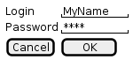
An example of the “Hello word” type
Here and so everything is clear:Code to create this picture
 @startsalt
 {
   Login |  "MyName"
   Password |  "****"
   [Cancel] |  [OK]
 }
 @endsalt
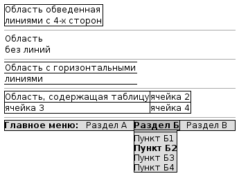
Draw frames, areas and tables
Code to create this picture
 @startsalt
 {
     {+ Area circled
     lines from 4 sides}
     ----
     {Area
     without lines}
     ----
     {- Area with horizontal
     lines}
     ----
     {# Area containing table | cell 2
     cell 3 | cell 4}
     ----
     {* <b> Main menu: |  Section A |  <b> Section B |  Section B
     <b> Section B | - | Point B1 | <b> Point B2 | Point B3 | Point B4}
 }
 @ endsalt-
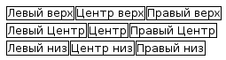
Divide the interface window field into areas (frames)
Basic principles
Code to create this picture
 @startsalt
 {
     {
         {+ Left Top} |
         {+ Center top} |
         {+ Right top}
     }
     {
         {+ Left Center} |
         {+ Center} |
         {+ Right Center}
     }
     {
         {+ Left bottom} |
         {+ Center bottom} |
         {+ Bottom right}
     }
 }
 @endsalt
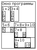
More complicated example
Code to create this picture
 @startsalt
 {+ Program window
     {
         {+ 1 + 2
             {+ 1}
             {+ 2}
         } |
         {+ 3 + 4
             {+ 3}
             {+ 4}
         }
     }
     {
         {- 5 + 6
             {+ 5} |
             {+ 6}
         } |
         {# 7 + 8 + 9 + 10
             {+ 7 + 8
                 {+ 7} |
                 {+ 8}
             }
             {+ 9 + 10
                 {+ 9} |
                 {+ 10}
             }
         }
     }
 }
 @endsalt
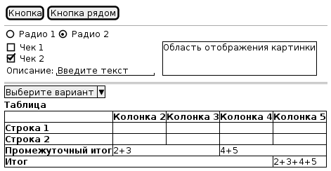
Examples of using elements and interface layouts
Using Controls and TablesCode to create this picture
 @startuml
 salt
 {
     {[Button] | [Button next]}
     ----
     {() Radio 1 | (X) Radio 2}
     {
         {
             [] Check 1
             [X] Check 2
             {Description: | "Enter text"}
         } |  .  |
         {+ Image display area
         .
         .
         }
     }
     ====
     ^ Choose an option ^
     <b> Table
     {#.  |  <b> Column 2 |  <b> Column 3 |  <b> Column 4 |  <b> Column 5
     <b> Line 1 |  .  |  .  |  .  |  .
     <b> Line 2 |  .  |  .  |  .  |  .
     <b> Subtotal |  2 + 3 |  * |  4 + 5 |  *
     <b> Total |  * |  * |  * |  2 + 3 + 4 + 5
     }
 }
 @enduml
Form with frames, tree and horizontal bookmarks
Code to create this picture
 @startsalt
 {+
     {
         . | <b> Informational
         . | <b> system
         {/ <b> Objects |  Directories |  Setup}
     }
     {#
         {
             {Wood type: | ^ By address ^ By value ^ By year built ^}
             {T
              + F.krug
              ++ Area
              +++ District
              ++++ Locality
              +++++ Street
              ++++++ House
              +++++++ <b> Apartment
             }
         } |
         {
             {/ <b> Specifications |  Plan |  A photo }
             .
             {
                 {#
                 .  <b> Parameter |  <b> Value
                 <b> Number |  66
                 <b> Number of rooms |  2
                 <b> Total area, m2 |  40
                 <b> Living space, m2 |  26
                 }
 {[<& list>] | [<& print>] | [<& folder>]}
             }
         }
     }
 }
 @endsalt
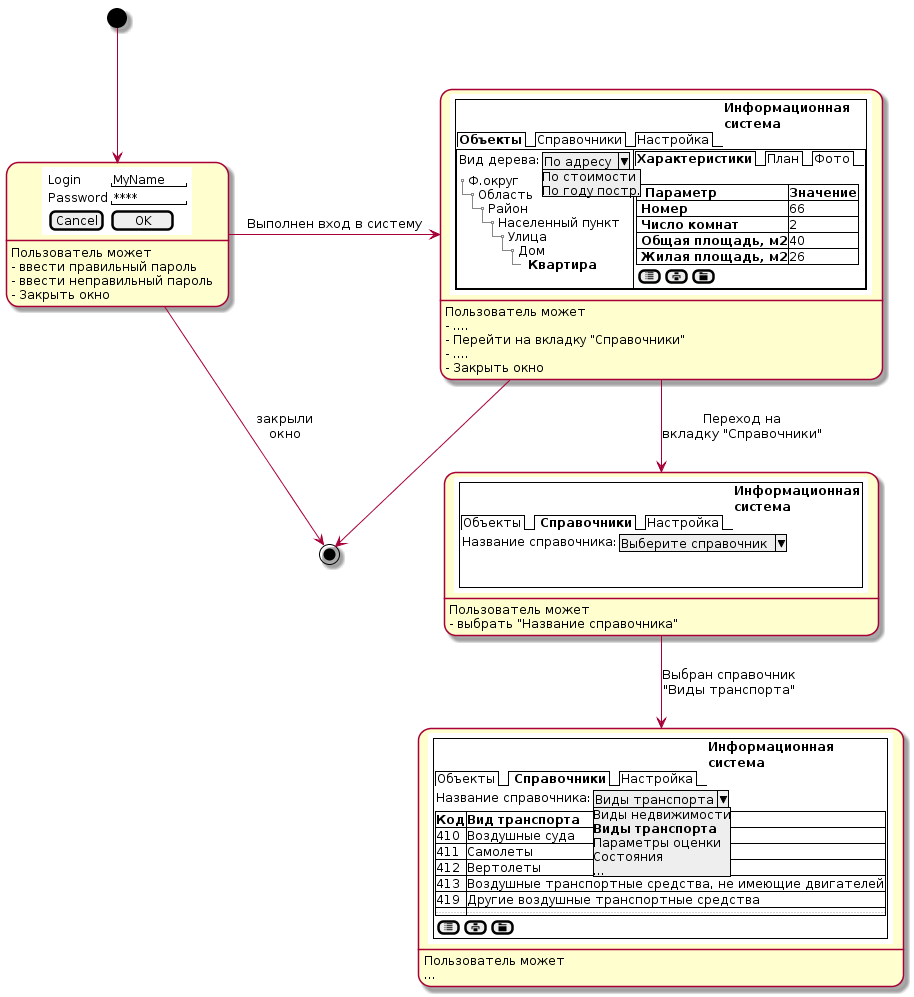
Dialog Map
Actually, the idea here is in a combination of state diagram notation and the possibility of nesting in each block of the State type a picture - a project of the interface form produced with the help of Salt. That is, it turns out like a picture in a picture. Inside each state, you can describe the possibilities of transitions, and provide the transitions themselves with comments describing the actions in the interface that caused them. In general, something like this ...Code to create this picture
 @startuml

 state "<img http://plantuml.com:80/plantuml/png/SoWkIImgAKxCAU6gvb9GyCbFpynJ088Q1INVIh_4t5GWMmae4P1ON5oUNvG2aj020f0Qi4IqSs9UScfEB50.p
 state "<img http://www.plantuml.com/plantuml/img/VLHTIy9W5BxtLnm8kZ4i9Bm8aNv4Tw5GP228XUvk6vX6KGb1H4LG5XdThfemvrn_uRp_gEUy6ulfRE8uUv_pFETps-uOUssZizSqScQUSeJBr7Uv2bPvly8FF5Ed7Aek1-oeC_Ouv1b-ZhfEUweJzjI9wl5OF1FCN2UHUUPFTGd8LprrHHRnA_z0q-4lQ9z3psEVFG6U80qPW25FSEYGhSMYkxdofvnO-ebleE4Ikpm6TmnXPykgyP13GXXNpg3RZqvqeY480SABxSMUtpXrLP_u9m9Kjr2pqu5sKe-K9nuLmF9LL_NvUmu4Yj9v6XSrc8U1lo2zYNIL5i1yt0wKCyKVVLTNF45oY3IJNYuoG7c3iuTHEHaeu5l42YWBo-jHFKhhK0oQ8XDAEVwrmYPhsIIYYR-B24hpPILWHSkHZ7aeFK7DC4TeDQP1wJuNqgBfVDERa51qu64SE41Op0yHvFHUx-ovxgB7umKkVAJPeQO9gLIYRASFAGNPOrjyxI_2FJ2AImYo-nVomiXMWISFMBB16d5G16zp8vjtXqId__2A6HdQENEtlDfiT8nArO9rt6wqOlFmg7bGRrUgDYqRQVoUsRdjUkj0lWg_>" as State2
 state "<img http://www.plantuml.com/plantuml/img/RP0n2i9044NxFSNqGkn592S9HBGJ2vDk4p115BGGh6mKlC562Ax1n2lykP6p2OYYC_2B-N_UBkD7SRY8et0MAzqZHLAwLLTUCXoFS4JDApIyn0E6rx1eK4iRtdydEOFbZ7EKBldsT9zmHi5RcLUSyuuIaZJXWgT03Qu2tmZGee8L4oTX2qVC1dSP6afRMgUQj4lW9ekcNIj9dlvbcK4IuC0x52Z5jEvdVvD11_O-D5MfygVpYRlC2m00>" as State3
 state "<img http://www.plantuml.com/plantuml/img/dL9TIm9157tVNp4Gz59iMRqK8lwFSC7GG10BtRSTmO_eIqY87YAew1zijbEhwVGNxlr7dJkP6KeFpJB3SE-vvznxTlADi5WF6yLgw4LhobDOaJjb-JfxaADRcl09MMxHc68-fPGiJV35tF-Dv3QbtEOE6K7ESj66eWTwval4HzpXdj8AQ4LFz07Ic0OWFmDXIYDAaQHxS8C7IKj316FLT6nVPwGYGT0R2cDNPXIa5xdYFHtGDQu9D1qTu8AKOT1c_9D5XQ44rIczOe-1a47IG0puc-8HpKfuJ4O0GcRXaW4bnWamvHUNvRxqnVt0z_rWEigAE45tc3FHCwcbGjvEPbCZRp5tmbq-Hxhd9kSkEfTyHaDC6h7qxfhf8RWbHSPnp8Utbt8jwiv4McAG6mIkhpl3b7FAy1LVk9ymDV05XiWRW1WD8RMhwGPSNIGSQl1_NG_MQMmrznnaUT5-ThLQQOIvWiRjk5wfJQ-7HzLIkPuhDBzBcbw-N2l9W_y4>" as State4

 [*] -> State1
 State1 -> [*]: closed \ nwindow
 State1: User can
 State1: - enter the correct password
 State1: - enter the wrong password
 State1: - Close window

 State1 -> State2: Logged in
 State2: User can
 State2: - ....
 State2: - Go to the "References" tab
 State2: - ....
 State2: - Close window

 State2 -> [*]
 State2 -> State3: Go to \ n "Directory" tab
 State3: User can
 State3: - select "Directory Name"

 State3 -> State4: Directory selected \ n "Modes of Transport"
 State4: User can
 State4: ...

 @enduml
I draw your attention to the fact that at the beginning of this code, the State elements are declared, containing references to images created in the same environment.
Conclusion
As I wrote at the beginning, of course this is not an interactive prototype that provides a complete imitation of the behavior of the system. But how much time will it take to create such a prototype? Will the imitation in the prototype really be complete? And is your Customer ready to agree (approve, sign) an interactive prototype, and not a paper document (in the case of software development upon request)?Karl Witgers in the 15th chapter of his "bible of business analysis" calls such prototypes "paper" and "low-quality", but emphasizes their usefulness for "studying the functionality and flows."
Thank you for attention.
')
Source: https://habr.com/ru/post/279373/
All Articles