Do I need a microscope when connecting “patchcords”?
If, working with fiber optics, you always use a microscope and specialized cleaning tools, you can not read this note. If the need to use a microscope when connecting “patchcords” caused you bewilderment, this review is for you.
When switching fiber-optic ports of active network equipment and cable systems, many, unknowingly, use methods of working with copper-core patch cords. Is it correct? In general, those and other cords solve the same problem, two data transmission channels are connected, and the procedure is similar in appearance, but, as they say, there are nuances, and they will be discussed under the cut.
')
A typical situation: the connection of two fiber-optic ports turned out to be in doubt - something is not working or is working unstable. Experience with electrical circuits leads to "move the contact", disconnect-connect several times, you may be able to quickly get away from the "routine" and do the "more interesting and important" business. But if with electric contacts such an approach often worked, then in optical connections, these movements can only worsen the situation, and even lead to serious damage in the zone of connection of the waveguides.
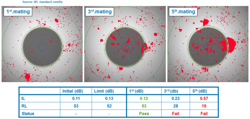
In most cases, the deterioration of the parameters of the VO connection causes clogging of the contact zone, as well as oxidation (clogging) of the electrical contact. But unlike the electrical contact, where during the re-switching, the galvanic contact zone can be cleared from the oxidation film (clogging), with several distortions of the optical connection, the pollution shifts to the center of the waveguide.
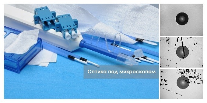
I can not believe - see pictures:
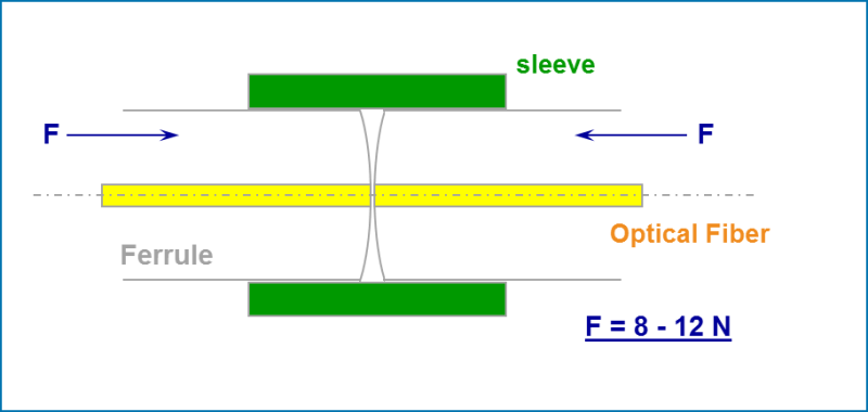
In VO connections, with which, most often, now, IT specialists have to work, as well as in electrical contacts, there is physical contact. Thus, in the LC-LC, MPO-MPO or SC-SC fiber-optic connection, two quartz glass waveguides (of the same kind as fragile as the glass we deal with in everyday life) are pressed together, approximately with a force of 10N ( 1kgs). Moreover, the contact patch is very small, less than 125 microns. And if, when connected, something harder or as hard as glass gets into the contact zone, then damage is inevitable.
For cleaning optical compounds, more and more often lately, we are aggressively offered to use expensive special cleaning products - “What, marketing again? What's worse is the old way: rubbed the connector on the shirt and you're done, did it work before? ”
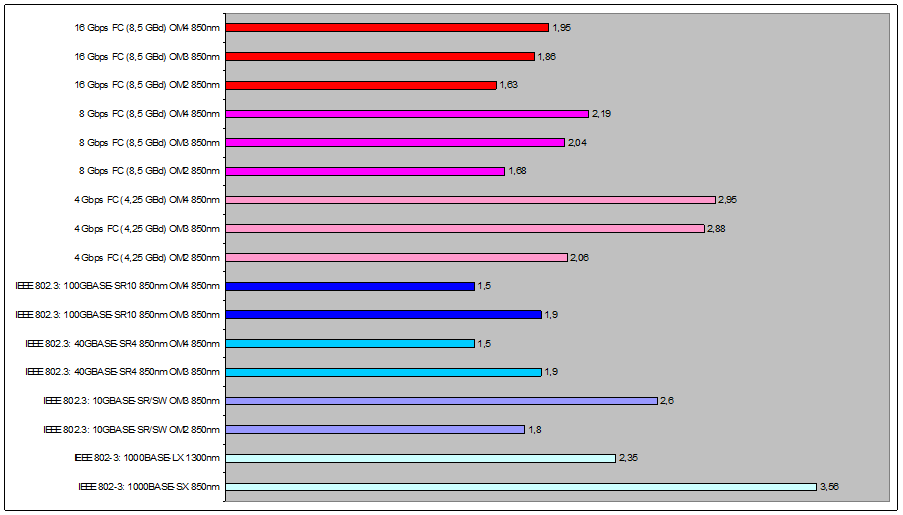
Previously, when Enterprise Networks used mainly Ethernet on VO lines, the application loss budgets for channels were quite large (the loss budget is the maximum part of the transmitter signal, after losing which, the application will stop working stably), for example 11dB for 100BASE- FX and, respectively, the VO channels were less sensitive to contamination. The requirements for the applications that we use today are much tougher. Simply touching the “clean” hand immediately causes contamination of the VO end of the connector and signal loss in the channel can go beyond the budget of the loss of the working application!
The figure below shows the loss budgets of today's most commonly used applications in Enterprise Networks, DC (values are in dB):
How to inspect and switch fiber optic connections correctly is described in IEC 61300-3-35, ISO / IEC 14763-3 . In short, the standards suggest connecting VO connectors only directly after positive visual inspection of both VO connectors . If necessary, during visual inspection, the standard proposes the use of specialized cleaning products, and, lastly, there must be a dry cleaning.
Without a microscope, a person cannot visually assess the state of the VO connector surface, therefore, the above standard suggests using an optical or video microscope with a magnification of at least 100x for inspection.
In order to practice, it was possible to always arrive in accordance with the requirement of the standard, you must have a 200x or 400x video microscope and a set of adapters that are necessary for it. Only a video microscope allows you to look into the VO switchboard adapter, the cassette adapter, the pre-terminated solution into the transceiver of the active equipment. A video microscope minimizes the likelihood of dangerous laser radiation on the human retina when inspecting connectors. The video microscope allows you to very quickly capture what he sees in the photo and save it in a file. At the same time, a video microscope is the most expensive instrument needed to inspect BO connectors. Leading manufacturers of video microscopes: EXFO, JDSU, FLUKE, Anritsu.
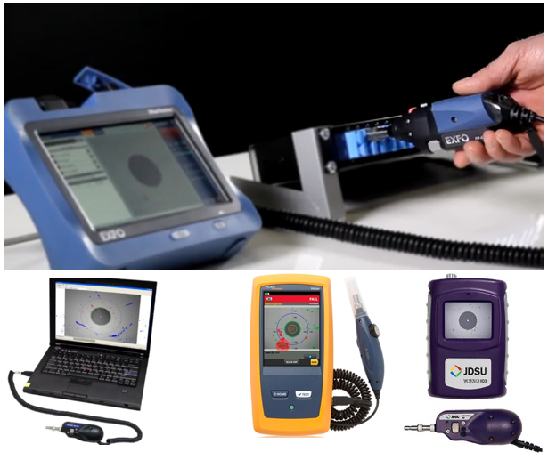
The video microscope can be connected to the USB port of a computer or to a smartphone.
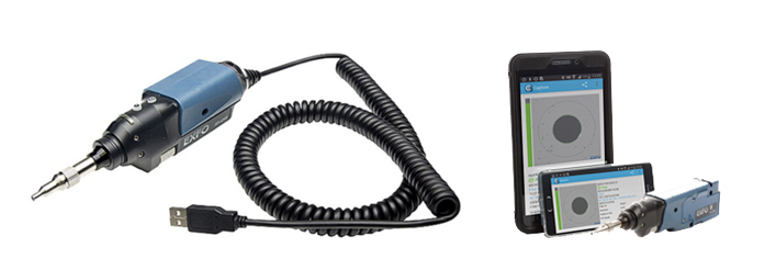
Under the link below, you can watch a funny commercial from EXFO, where their new video microscope with wireless image transfer to the smartphone is demonstrated:
www.exfo.com/library/sales-marketing-resources/product-demos-interviews/bu3-fip-435b-wireless-probe-demo
Specialized software automatically analyzes the image of the state of the surface and gives a conclusion in accordance with the requirements of the IEC 61300-3-35 standard.
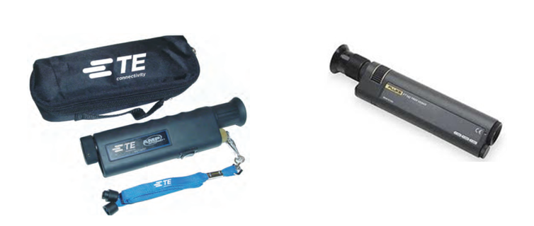
The optical microscope 200x or 400x (100x does not allow to see everything that is needed) is much cheaper than a video microscope, it allows you to make out smaller details, it is more compact and easy to use, it solves the main share of inspection tasks. Therefore, it must be used during the installation of VO systems. But, unfortunately, the optical microscope does not allow you to look at the VO connector in the adapter, in the adapter of the cassette of a predetermined solution, in the transceiver of the active equipment, with it you cannot analyze the state of the optical ports of the test instruments (LSPM, OTDR). Optical microscopes, along with the companies listed above, are producing component manufacturers for building structured cable systems: COMMSCOPE, TE Connectivity, Panduit, SIMON, R & M ...
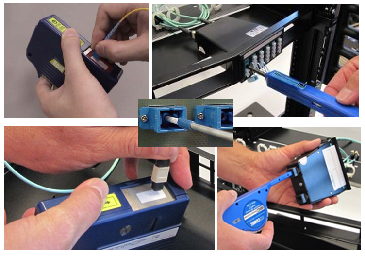
Almost all optical microscopes use the main mode of direct illumination, through a prism perpendicular to the inspected surface. Some manufacturers offer another backlight mode, (the backlight goes sideways at an angle to the inspected surface). This mode is usually optional. To fully utilize the capabilities of an optical microscope, experts suggest using three inspection approaches:
- in direct backlight mode, without backlighting of the VO line at the other end
- in sidelight mode, without backlighting of the VO line at the other end
- in direct backlight mode, with backlighting of the VO line at the other end
Under the link below you can see more detailed information on this issue:
www.thefoa.org/tech/ref/testing/test/scope.html
So, only after inspecting with a microscope can we be completely sure that we connect the connectors that are really clean and not damaged.

If you have not yet decided to purchase a video microscope and are working in an active VO network with an optical microscope, it is not even superfluous to have one more tool, the identifier of the active fiber. The fact is that an optical microscope, used mainly for mounting, is not always equipped with a protective eye filter (so as not to increase the cost). The identifier of the active fiber is connected, like a clothespin, to a thin cable of a semi-cord or connecting cord and allows you to see the presence of a signal dangerous to the human eye that the eye itself cannot see. Such a device may allow to estimate approximately the power level and the direction of the optical signal in the fiber.
Using a microscope and trying to clean the contaminated connector with the help of available tools, I think you quickly see that this is not so simple as it seemed. After kitchen napkins, a small pile is surely present, and they become limp when moistened. Wet sanitary napkins may not leave a nap, but we can only guess what they are soaked with ... So what kind of special cleaning products do we suggest?
Specialized cleaning products / tools solve a number of tasks:
- get rid of pollution as quickly and efficiently as possible;
- minimize the likelihood of damage to components when cleaning. (The more approaches, when trying to clean the surface, the higher the chance of scratching it. If you have to remove the VO connector from the adapter to clean it, there is a chance of breaking or creating a macrobend in the fibers of the semi-cords);
- cleaning of VO connectors, which, in principle, are not possible to extract from the adapter (cassette of a preterminated solution, the port of active equipment).
The market has long proved cleaning tools, in which the cleaning element is in a closed plastic case. Due to the closed cartridge of automatic cleaners, the cleaning element, lint-free thread or fabric tape, always remains clean and every new cleaning is done with a really clean, untouched part of it, the thread / tape is rewound every time to go from one reel to another. the time of one simple movement for man.
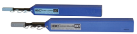 | Automatic IBC optical connector cleaners - for cleaning the VO connectors installed in the adapter panel, cassette of a predetermined solution or in the transceiver of the active equipment or the test instrument connection port (LSPM, OTDR). It can also be used to clean non-connected BO connectors. The photo tool for VO connectors with a ferule of 2.5 mm and 1.25 mm. Allows you to perform more than 500 cleanings. |
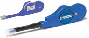
 | IBC cleaner - for cleaning two LC duplex fibers at once, it may be interesting for large-scale switching and will speed up the cleaning process. |
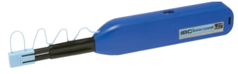
 | IBC cleaner - for cleaning multi-fiber VO MPO connectors: in the adapter of a preterminated cassette, in active equipment, as well as trunk-cable connectors and MPO-MPO connecting cords. Manufacturers of pre-installed solutions with MPO connectors require that you use this tool for installation. |
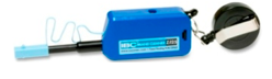 | IBC cleaner - with a shortened case, it may be indispensable in hard-to-reach places, but the resource is lower than that of a normal one. |
 | Closed cassette with a rotatable replaceable cartridge - for cleaning of VO connectors of all types, but not fixed in the adapter. Replacement cartridges can be ordered separately. This tool is most effective for VO connectors, since, unlike IBC cleaner, it allows you to completely clean the entire surface of the ferrule face, not just the contact area. |
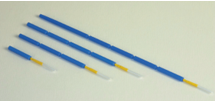 | Cleaning sticks 1.25mm and 2.5mm - there are different. Most of them are intended primarily for cleaning the guide inside the VO adapter and are not very effective for cleaning the end of the VO connector installed in the adapter. It is productive to use sticks together with a balloon with compressed air, as the stick cleans only the surface of the guide bush on which the ferule slides. |
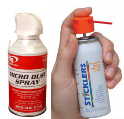 | Cylinder with purified compressed air (or special gas) - for cleaning the working area of the adapter's VO from large particles of pollution. Only a cylinder is available to clean the cut of the adapter bushing and other cavities where contamination can accumulate. The balloon can also be used, if necessary, to moisten dry products. Using cylinders that are not specialized for VO, you risk seriously clogging the adapter and VO connector, because any impurities can be contained in the unpurified air, during compression and transition to a liquid state in the cylinder, their concentration greatly increases. |
 | Various lint-free napkins of open type (without a closed cartridge with a broach) - less cost, but clog up faster |
 | Wet wipes (soaked with isopropyl or other special composition) - when dry cleaning can not cope. One of the most affordable cleaning products. Each napkin in a separate sealed package, which is very convenient, each guaranteed clean even in the most severe conditions. Although the first purpose of these napkins is assembly work, they are also used for maintenance. |
| Wet wipes with special active impregnation - when dry products and isopropyl can not cope. | |
| Someone, for moistening the above dry products, instead of isopropyl, uses 96% ethyl alcohol, but it is not always clean and there is water in it. |
There are also portable automated cleaning systems on the market. Such a system may be required when testing or servicing objects with a large number of VO connections. Click here for a description of the JDSU CleanBlast automated contactless cleaning system: www.fiberoptic.com/mmfiberoptic/PDFs/CleanBlast%20Benchtop%20Unit.pdf
All this time we have been talking about how to maintain the cleanliness of the VO connectors, but the VO connecting cord is also a cable (also, it only looks a little like copper-wire). Under the sheath and other protective elements of the VO cable design are quartz waveguides. And despite the fact that we emphasized above the fragility and vulnerability of the surface of the end of the quartz waveguide, the fibers in the cable construction are protected quite well and allow us to work with the cable of the connecting cords almost as much as with the cable of copper and copper wires. But, with the only difference that the unacceptable deformation of the copper-core cords, which also leads to the loss of the line parameters, is not as noticeable and does not lead to a complete rupture of the transmission line, as can happen with the VO cords. When the cable VO of the cord is bent less than the allowable radius, losses grow at the site of the bend (part of the signal goes beyond the waveguide), with a further decrease in the bend radius, the losses increase until the fiber breaks (like straws). It is characteristic that if, in the process of random deformation, the fiber did not reach the critical break point, restoring the bending radius of the cable, we will recover the loss at the bending point of the fiber. There are cables, both copper-core and fiber-optic, the shell of which “remembers” the violation, whitens in the place where the minimum bending radius was exceeded. But, so far, such cables can be seen not often in our projects, therefore, damage to the fiber of the cord may not be visible during external examination.
From the above, it can be concluded that the fiber of the connecting cord, the bending radius of which is not broken at the moment, can usually have two states: whole or broken. Moreover, the losses in the fiber of a short VO cord, without breaking the bend radius, are insignificant, compared to the losses on its connectors.
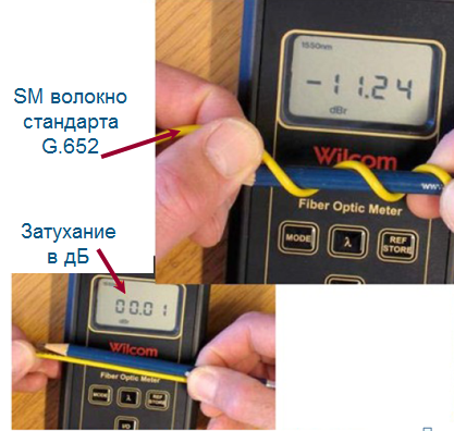
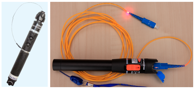
You can check the integrity of the fiber short cord with any flashlight. And you can use for this special "flashlight» VFL (Visual Fault Locator). This is a tool with a special laser source whose spectrum sees the human eye, 650nm (635-670) red. And of course the power of this source is normalized to the eye-safe level (as a rule, they use devices with a Class 2 laser, with a power of 1mW or slightly higher). Nevertheless, the signal of such a source is not directly looked at, they are looking at light scattered or reflected from some surface. With this tool, you can not only check the integrity of the fiber cable IN the cord, but also to see the location of the damage to the fiber under the intact cable sheath. The scattered light of such a laser source, at the point of breaking, will make its way through the protective buffer of Kevlar and cable jacket.
VFL will allow analyzing whether the fiber is intact, whether the half-cords in the VO panels are correctly laid, whether there are macro-bends (small sections of the fiber where the fiber is deformed by the external environment, for example, pinned fiber). On the semi-cords with white buffer, macro-bends are clearly visible, violation of the radius when laying. The VFL signal, unlike the usual flashlight, passes without loss, VO lines are much longer and you can already confidently check the trace or fiber integrity of the entire VO channel, from port to port of active equipment, including all intermediate connections. When purchasing a VFL, you should not make a choice according to the rule: “the more powerful the better.” The main task of this device is a visual analysis of nearby, nearby events (where it can be harder and less convenient to see the damage with an OTDR), rather than the “illumination” of long lines. There are VFL on the market with a capacity of 10mW and 20mW, with marketing inscriptions 10km, 20km. Radiation, with a wavelength of 650nm, attenuates fairly quickly (about 7.5 dB / km in G.652 fiber) and I think it will be difficult to see something after 10km from a 10mW source. But, by chance, just look at the signal, which causes a slight dizziness, if you just looked at his reflection from the wall in the room - a pleasant little.
There may be situations when VO connectors in a microscope look good and the fiber is intact, and the connecting cord raises questions:
- For example, if you, by mistake instead of VO of the MM cable, try to connect the SM cable. These cords may have the same and compatible form of VO connectors, only the color marking is different. And most importantly, these cords have a different type of fibers, and with such a connection, the connecting cord will be a place of huge losses.
- If you connect a VO line with OM3 or OM4 fiber, a cord with the same connectors, but with OM2 fiber, be prepared for a small increase in losses (more so because the grinding and control accuracy of OM3 / OM4 is higher than that of OM2 cords )
- The case when you decided to use a VO connecting cord from the manufacturer “cheaper”: the fiber is whole, the ends are clean, but you have no way to evaluate the geometry of the ends of the VO connectors, the displacement of the fiber relative to the center of the ferule, this is done only in production and only serious manufacturers. To understand this situation, you will have to analyze the IL (Insertion Loss) and RL (Return Loss) parameters, they are indicated on the packaging for each connector. And you will have the opportunity to learn that the RL parameter, for the operation of the application, is as important as IL, and that Ethernet stops working stably if the Total RL channel is less than 12 dB. Another example is when a clean, with a whole fiber connecting cord, from the manufacturer mentioned above, works fine, but for some reason, sometimes it loses connection, as if someone didn’t specifically insert a VO connector until it clicks (seen with VO type SC connectors). This situation may occur more often with fluctuations in ambient temperature.
But even with the use of high-quality components in VO channels, there are situations that require more attention. If you checked the trace, fiber integrity and connector cleanliness, and you still have doubts about the VO line, measure IL (Insertion Loss) real signal loss in the VO channel from the port to the active equipment port, compare them with the estimated loss budget for the VO channel and with a loss budget for the active equipment application that you are currently connecting. To do this, you need a test signal source with the same wavelength as the active equipment, and test connecting cords. The kit of such a meter is called the LSPM (Light Source Power Meter). If using LSPM you have verified that the VO channel is not working, for localizing and eliminating the cause, you will need to use more expensive test equipment that is used when installing VO lines, but this is another topic for conversation.
SKS department of MUK group of companies
All questions on SCS: scs@muk.ua
Distribution of SCS solutions in Ukraine and CIS countries
MUK-Service - all types of IT repair: warranty, non-warranty repair, sale of spare parts, contract service
UPD by comments: The author of the article emphasizes that the channels of the SCS and the data center are the most sensitive to pollution in the VO, since the applications that are used today have a very small loss budget. It will be the same with a single-mode backbone telecom if the channel’s insertion loss is close to the loss budget of the application that is used for reception / transmission. For field conditions, the military use contactless HE connectors, which can be “rinsed in a puddle” and everything will work, but the note is not about them.
The author tried, in the framework of a condensed article, to share systematized information about the intricacies of servicing VO channels of SCS, which everyone does not have time to deal with, but somehow have to do the work. There are no sensational discoveries in the article, just to deal with these simple things, you need to spend time, go through a series of mistakes, sometimes expensive mistakes.
Once, one of the installers' partners asked the question, “Is it possible to replace the ferrule of the connection port of the OTDR?”. The device, costing 20kUSD "turned into a brick with a flick of the wrist" by mistake or because of inexperience. Another case: at one of the installation sites of the data center, something did not work for the installer to work with OTDR. As it turned out, the installer used OTDR for many years without a microscope, and he did not think that he needed to monitor the cleanness of the connection port very strictly. This installer was very surprised when he saw the state of the port of his reflectometer under a video microscope and when he understood why his OTDR lost almost half of its dynamic range. But it was too late to clean something, the surface of the ferule was covered with shells and scratches. The active equipment transmitter port has the same physical contact as the OTDR connection port.
It is quite natural that the omnipresent intrusive marketing has already developed defensive reflexes for us. “If they write about something, it means they want to“ push ”something. But the task of publication is not to massively sell video microscopes and cleaning products, but the fact that we (scs@muk.ua) can help solve the issues of organization design and competent support of cable infrastructure of an office facility, an industrial enterprise or a data processing center, on based on the products of the leaders of the SCS market
Source: https://habr.com/ru/post/279189/
All Articles