HPE Intelligent Resilient Framework Virtualization Technology
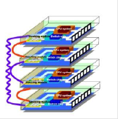
Today, ICT is widely used virtualization technology. It has long gone beyond server virtualization, when several virtual machines are running on the same physical server. This approach, called 1: N virtualization, is also applicable to the network: at the first stage of development of network technologies, VPN or VRF technologies were used to isolate logical segments. At the next level of development, the possibility of hardware virtualization has appeared, when several images of the operating system are launched on one physical switch. This approach allows you to create several independent devices that use such common resources as control modules (CPU, memory), chassis (factories, cooling) and power supply system.
However, another option is also possible: similarly, combining several physical servers into one logical, several physical network devices are combined into one easily manageable logical device. This approach is called N: 1 virtualization. Along with simpler administration, it helps improve network reliability, increase port density, and provides a number of other benefits, which we will discuss below.

Virtualization is 1: N (several virtual switches work on the same platform) and N: 1 (several physical switches form one logical device).
Currently, there are several switch virtualization technologies that allow you to combine several physical switches into one logical switch, for example, Juniper Networks “virtual chassis” technology, Cisco Virtual Switching System (VSS) and HPE Intelligent Resilient Framework (IRF). The IRF technology developed at the time by H3C is the classic N: 1 virtualization.
')
In any case, when virtualizing N: 1 switches, a certain pool or stack of devices is created. To combine them, both dedicated dedicated interfaces and regular Ethernet ports 1/10/40 / 100G can be used. In the latter case, the switches can be separated by a considerable distance: the logical switch is obtained geographically distributed. Sometimes switch virtualization technologies are referred to as stacking technologies, virtual stacking technologies (as in the case of IRF) or clustering (for example, as in Huawei technology CSS / iStack).
The data processing level (data plane) is active on all devices forming the logical switch, that is, they all provide packet transmission. The control plane (control plane), which is responsible for the logic of the switch, can be operated on a single device (master). It is responsible for handling network protocols (L2 / L3), ACL, QoS, routing tables, etc.
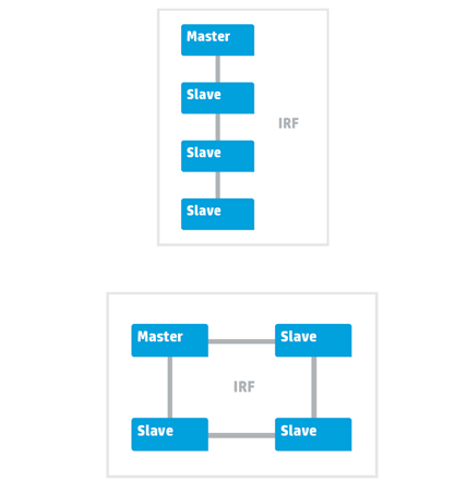
Two topologies: tire and ring
There are two possible connection topologies of switches within the framework of the IRF: bus and ring. The latter is recommended, as it is more fault tolerant. The merged switches begin to exchange packets to build a common stack topology. Next, based on the transfer of packets within the stack of IRF.
Switch virtualization technologies allow overcoming the limitations of the traditional network architecture with the Spanning Tree Protocol (STP) - considerable recovery time in case of failures, inefficient use of bandwidth, difficulties in configuration, troubleshooting, etc.
To solve these problems in ring topologies, technologies such as Resilient Packet Ring (RPR), HPE Rapid Ring Protection Protocol (RRPP) and Ethernet Ring Protection Switching (ERPS) were developed. They provide a short recovery time (50 ms) in the event of a fault in the ring.
For the networks built on the classical star topology, these technologies are hardly applicable. One of the options for optimizing such networks was the use of N: 1 virtualization technologies. The use of HPE IRF class technologies at the kernel / network distribution level ensures high fault tolerance without complex protocol support.
At the access level, such technologies can not only overcome all the shortcomings of the traditional STP protocol, but also significantly reduce the total number of control points. Their advantages are obvious - there are no problems with STP, loops, blocking ports, creating L2 domains, plus ease of administration.

Ring network structure
HPE IRF technology allows you to create fault-tolerant networks with fast convergence, easily manageable and scalable. The IRF switch group, which forms a virtual logical switch (and this can be up to nine devices - depending on the model), has one IP address, which simplifies configuration and management.
One switch in the group is the main one; it provides the control plane (control plane), updating the forwarding and routing tables for other devices. That is, all control is exercised by the main switch, while its state is synchronized with the slave devices.
Switch stack
In case of failure of the main switch, the IRF instantly selects a new one - the service is not interrupted. If the link fails, one of the switches retains the role of the main one, the second switch enters the Recovery State and disables all ports except the IRF ports and the “non-disconnectable” (as configured) ports. After link recovery, the switch that was in recovery state will reboot and become slave. A similar algorithm is used if two switches at once decide that they need to become active.
In the IRF domain, one of the switches can be disabled for maintenance or software updates - the so-called In-Service-Software-Upgrade procedure (ISSU). This will not affect traffic.
IRF technology provides the ability to stack switches, receiving a total of up to 1024 Ethernet ports. For the interaction of devices in the IRF group, normal Ethernet ports are used, in most cases - 10 Gbit / s. An IRF channel is formed between the switches, and the packets transmitted through it are provided with an additional header (IRF tag). The components of such a logical switch can be placed in different racks of the data processing center or at different sites, at a distance of 70 km from each other.
IRF extends to access, aggregation, and network core levels. With IRF, you can reduce the number of network layers by combining access functionality and aggregation or aggregation and core. Boundary or aggregation switches that interact in a network with kernel-supported IRF switches see associated switches as a whole, so there is no need to use technologies such as STP.
The use of IRF provides several advantages over traditional networks. We have already told about some of them. Basically, these benefits cover three areas: simplicity, performance, and reliability.
Simplified Network Infrastructure
The network infrastructure is becoming simpler — not three-level, but two-level. It has fewer devices, interfaces, connections, and protocols that require configuration and control. A two-tier network requires less equipment and simplifies network administration in data centers and campus networks of enterprises.
Centralized management and configuration
IRF does not require to connect to each device and manage it individually. For configuration, the main switch is used, and all settings are distributed to its associated devices. In this approach, this is reminiscent of SDN - software-configured networks.
To allow network administrators to use not only the command line, but also a more user-friendly interface, the HPE Intelligent Management Center (IMC) management system has been developed. It allows you to manage the entire network in one console. The IMC network management system displays the network topology, manages configurations, devices, performance, simplifies diagnostics and troubleshooting.
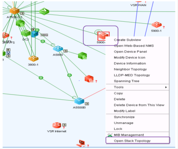
Network topology in the IMC interface
Reliability
Support for IRF in Link Aggregation Control Protocol (LACP) provides for the transfer of traffic between switches through several channels, and the restoration of the topology when a switch or link in the stack fails takes no more than 50 ms, while in the case of STP it can take several seconds.

Comparison of convergence time in ms using RSTP and IRF for channel failure, switch network card or chassis.
Thus, IRF allows you to create more reliable "flat" networks with fewer levels and devices. Compared to traditional network infrastructure, network latency is reduced, performance is increased, and the need for complex protocols that increase reliability is eliminated. Reduced capital and operating costs.
To increase the reliability of the IRF factory, you can use the N + 1 configuration. In addition, the IRF domain allows you to use the mobility of applications and virtual machines in the global network at the L2 level.
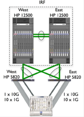
Configure IRF using the LACP protocol between the 12500 and 5820 switches. For the 5820 switch, the aggregated connection is one virtual channel. This allows you to create interesting disaster-proof solutions, where IRF and aggregated links connect geographically distributed switches.
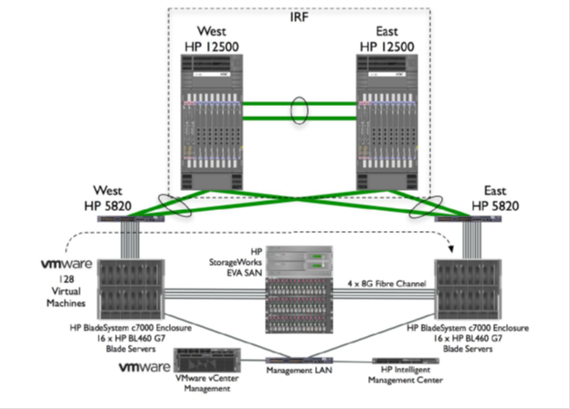
Testing the migration of 128 virtual machines (Vmware vMotion) in configurations using RSTP and IRF showed that in the latter case, higher performance is achieved.

When using RSTP, the vMotion migration process took about 70 seconds in three tests , and in the case of IRF only 43 seconds.
Performance
In the non-blocking architecture of the IRF all links are active, the bandwidth of the switching system is increased. Using IRF in conjunction with LACP also allows you to aggregate links between servers and switches, increasing network bandwidth for critical applications.
In the IRF domain, the network protocols function as one. This increases the efficiency of data processing, increases productivity, simplifies operations. For example, in the case of routing protocols, routes are defined in one logical domain.
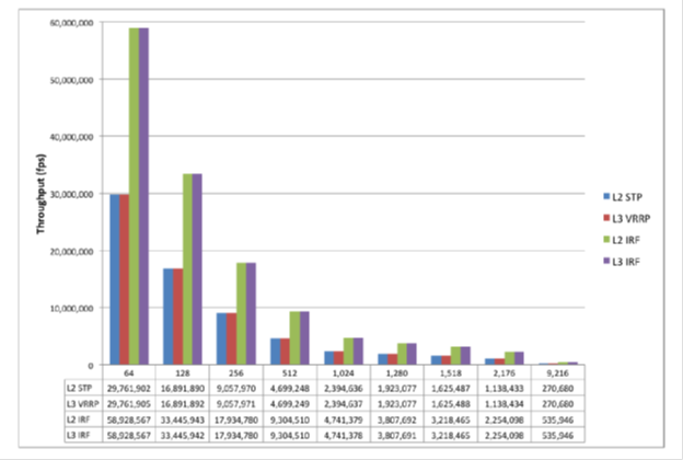
Performance comparison when using IRF and other L2 / L3 fault tolerance mechanisms.
Summarize. HPE IRF technology is:
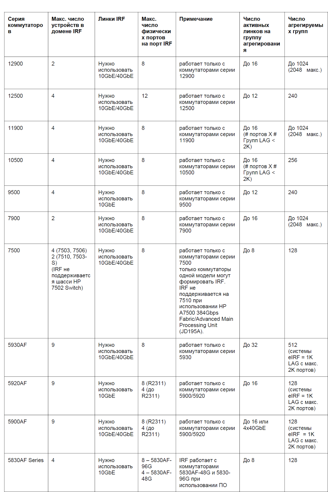
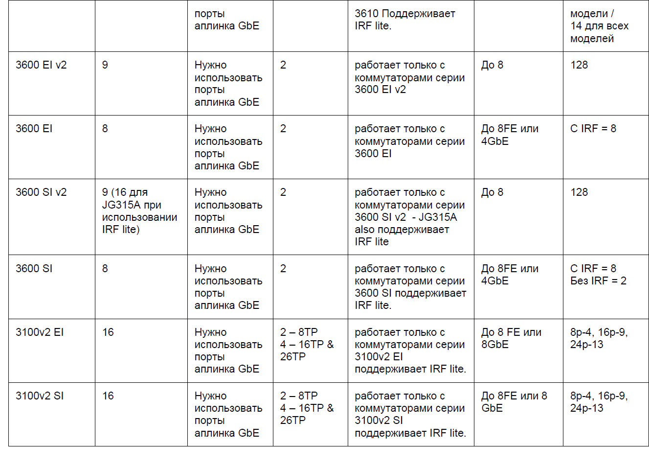
IRF is supported on all HPE switches, starting at 3600 and ending at 12900E, as well as on the entire line of routers running Comware OS 7. This class of solutions can be used in campus networks (core, distribution, access), in data center networks (core, distribution , access) in routed branch networks, especially where redundancy of routers is required in branch offices.
As the test results show, IRF demonstrates advantages in areas such as network architecture, its performance and reliability. Combining multiple switches and transforming them into a single logical fabric simplifies campus and data center networks, and speeds up the migration of VMware vMotion. Thanks to the active / active design, the IRF network has twice the bandwidth compared to the active / passive design. In addition, in L2 and L3 mode, the convergence time for failures is significantly reduced, network reliability increases and application performance increases.

These technologies are generally similar, but there are important differences. Like Cisco VSS, IRF technology provides aggregation of stack switch channels, uses the LACP protocol to match the parameters of the resulting channel.
As in the case of Cisco VSS, the control plane state is synchronized between the stack switches, and the failure of the main switch does not lead to a denial of service. However, the state of the routing protocols is also synchronized in the IRF, and in the event of a failure and subsequent recovery, the L3 connection does not break — in less than 50 ms the device does not have time to detect the failure of one of the switches. Cisco has a special NSF technology for this purpose; in the case of IRF, a similar technology is used - Nonstop routing (NSR) or rgaceful restart (GR).
Switching traffic flows during aggregation — adding / removing physical channels — in IRF takes about 2 ms, while at Cisco this value is 200 ms. Such a short time avoids additional mechanisms.
Unlike Cisco VSS, IRF technology supports a wider range of switches, including relatively inexpensive devices. Using IRF, you can combine switches of only one lineup. The exceptions are the 5800 and 5820 series switches, as well as the 5900 and 5920 series.
Let's compare now briefly the technology HP IRF and Juniper VC. They look like the following:
However, the VC has several disadvantages. VC is a technology for the EX4200 switch launched in 2008. Since then, there has been no significant investment in it. The company developed a completely different architecture - Qfabric.
With such limited funding in EX products, no significant innovations have appeared. For example, an EX4500 access switch with VC support used the same 128 Gbps bus that did not adequately respond to 10GbE traffic.
The EX8200 switchboard was well received by the market, but the EX8200 VC technology appeared some time later, and the internal Route Engines engines did not have enough power for the VC. The need to connect additional external controllers has complicated the decision. In addition, only a few line cards, mainly 8 SFP +, support the chassis connection.
In a configuration with two switches, if one of them fails, the second interprets this as a VC break and goes into an inactive state according to the VC disconnect policy. The whole stack is crumbling. This can be avoided by disabling gap detection, which administrators often forget.
Some maintenance operations require connecting to the console and entering CLI commands. And the use of built-in dedicated VC ports limits the distance to 5 m. The EX4200 switch in a VC configuration only supports 64 LAGs.
Formally, since 2013, VC can be used on the MX series routers, but there are strong limitations. Only two chassis are supported, with two routing engines each. Trio chipset is required. Not supported Enhanced Queuing DPC. Need a separate license. In addition, VC is not supported in MX5 / 10/20/40/80 hardware.
In the meantime, the IRF has been further developed.
The result of the evolution of IRF is Enhanced IRF (eIRF) technology. It allows you to create more complex hierarchical, including the kernel and access levels. Kernel-level switches (Controlling Bridges), the main and the slave, assume the functions of managing the IRF stack, and switches, the access levels are in fact port extenders (Port Extenders). Their main role is traffic transmission. There can be up to 64 access level switches. All of these switches (CB + PE) represent a single logical switch.
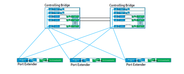
Kernel switches (CB) and port extenders (PE) with L2 / L3 forwarding function are a single logical device. PE extenders actually work as switch line cards.
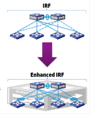
Unlike IRE, eIRF allows you to combine multiple physical devices at different levels
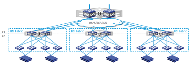
An example of building a network based on eIRF in the data center. Two switchboards of the distribution level IRF factory (at the top) are connected by reserved channels (uplinks) to the network core, the ToR switches (at the bottom) form the HA group. Each server in the rack connects to two such switches - port extenders.

An example of using eIRF in the campus network. Two switches of the IRF factory represent the core level, port extenders represent the access level switches. The latter form groups of HA and service devices on the floors of buildings. Each server connects to two switches.
Differences between IRF and eIRF
In conclusion, we will briefly list what the eIRF actually gives us:
However, another option is also possible: similarly, combining several physical servers into one logical, several physical network devices are combined into one easily manageable logical device. This approach is called N: 1 virtualization. Along with simpler administration, it helps improve network reliability, increase port density, and provides a number of other benefits, which we will discuss below.
Virtualization is 1: N (several virtual switches work on the same platform) and N: 1 (several physical switches form one logical device).
What is switch virtualization?
Currently, there are several switch virtualization technologies that allow you to combine several physical switches into one logical switch, for example, Juniper Networks “virtual chassis” technology, Cisco Virtual Switching System (VSS) and HPE Intelligent Resilient Framework (IRF). The IRF technology developed at the time by H3C is the classic N: 1 virtualization.
')
In any case, when virtualizing N: 1 switches, a certain pool or stack of devices is created. To combine them, both dedicated dedicated interfaces and regular Ethernet ports 1/10/40 / 100G can be used. In the latter case, the switches can be separated by a considerable distance: the logical switch is obtained geographically distributed. Sometimes switch virtualization technologies are referred to as stacking technologies, virtual stacking technologies (as in the case of IRF) or clustering (for example, as in Huawei technology CSS / iStack).
The data processing level (data plane) is active on all devices forming the logical switch, that is, they all provide packet transmission. The control plane (control plane), which is responsible for the logic of the switch, can be operated on a single device (master). It is responsible for handling network protocols (L2 / L3), ACL, QoS, routing tables, etc.
Two topologies: tire and ring
There are two possible connection topologies of switches within the framework of the IRF: bus and ring. The latter is recommended, as it is more fault tolerant. The merged switches begin to exchange packets to build a common stack topology. Next, based on the transfer of packets within the stack of IRF.
What is it for?
Switch virtualization technologies allow overcoming the limitations of the traditional network architecture with the Spanning Tree Protocol (STP) - considerable recovery time in case of failures, inefficient use of bandwidth, difficulties in configuration, troubleshooting, etc.
To solve these problems in ring topologies, technologies such as Resilient Packet Ring (RPR), HPE Rapid Ring Protection Protocol (RRPP) and Ethernet Ring Protection Switching (ERPS) were developed. They provide a short recovery time (50 ms) in the event of a fault in the ring.
For the networks built on the classical star topology, these technologies are hardly applicable. One of the options for optimizing such networks was the use of N: 1 virtualization technologies. The use of HPE IRF class technologies at the kernel / network distribution level ensures high fault tolerance without complex protocol support.
At the access level, such technologies can not only overcome all the shortcomings of the traditional STP protocol, but also significantly reduce the total number of control points. Their advantages are obvious - there are no problems with STP, loops, blocking ports, creating L2 domains, plus ease of administration.
Ring network structure
IRF features
HPE IRF technology allows you to create fault-tolerant networks with fast convergence, easily manageable and scalable. The IRF switch group, which forms a virtual logical switch (and this can be up to nine devices - depending on the model), has one IP address, which simplifies configuration and management.
One switch in the group is the main one; it provides the control plane (control plane), updating the forwarding and routing tables for other devices. That is, all control is exercised by the main switch, while its state is synchronized with the slave devices.
Switch stack
In case of failure of the main switch, the IRF instantly selects a new one - the service is not interrupted. If the link fails, one of the switches retains the role of the main one, the second switch enters the Recovery State and disables all ports except the IRF ports and the “non-disconnectable” (as configured) ports. After link recovery, the switch that was in recovery state will reboot and become slave. A similar algorithm is used if two switches at once decide that they need to become active.
In the IRF domain, one of the switches can be disabled for maintenance or software updates - the so-called In-Service-Software-Upgrade procedure (ISSU). This will not affect traffic.
IRF technology provides the ability to stack switches, receiving a total of up to 1024 Ethernet ports. For the interaction of devices in the IRF group, normal Ethernet ports are used, in most cases - 10 Gbit / s. An IRF channel is formed between the switches, and the packets transmitted through it are provided with an additional header (IRF tag). The components of such a logical switch can be placed in different racks of the data processing center or at different sites, at a distance of 70 km from each other.
IRF extends to access, aggregation, and network core levels. With IRF, you can reduce the number of network layers by combining access functionality and aggregation or aggregation and core. Boundary or aggregation switches that interact in a network with kernel-supported IRF switches see associated switches as a whole, so there is no need to use technologies such as STP.
IRF benefits
The use of IRF provides several advantages over traditional networks. We have already told about some of them. Basically, these benefits cover three areas: simplicity, performance, and reliability.
Simplified Network Infrastructure
The network infrastructure is becoming simpler — not three-level, but two-level. It has fewer devices, interfaces, connections, and protocols that require configuration and control. A two-tier network requires less equipment and simplifies network administration in data centers and campus networks of enterprises.
Centralized management and configuration
IRF does not require to connect to each device and manage it individually. For configuration, the main switch is used, and all settings are distributed to its associated devices. In this approach, this is reminiscent of SDN - software-configured networks.
To allow network administrators to use not only the command line, but also a more user-friendly interface, the HPE Intelligent Management Center (IMC) management system has been developed. It allows you to manage the entire network in one console. The IMC network management system displays the network topology, manages configurations, devices, performance, simplifies diagnostics and troubleshooting.
Network topology in the IMC interface
Reliability
Support for IRF in Link Aggregation Control Protocol (LACP) provides for the transfer of traffic between switches through several channels, and the restoration of the topology when a switch or link in the stack fails takes no more than 50 ms, while in the case of STP it can take several seconds.
Comparison of convergence time in ms using RSTP and IRF for channel failure, switch network card or chassis.
Thus, IRF allows you to create more reliable "flat" networks with fewer levels and devices. Compared to traditional network infrastructure, network latency is reduced, performance is increased, and the need for complex protocols that increase reliability is eliminated. Reduced capital and operating costs.
To increase the reliability of the IRF factory, you can use the N + 1 configuration. In addition, the IRF domain allows you to use the mobility of applications and virtual machines in the global network at the L2 level.
Configure IRF using the LACP protocol between the 12500 and 5820 switches. For the 5820 switch, the aggregated connection is one virtual channel. This allows you to create interesting disaster-proof solutions, where IRF and aggregated links connect geographically distributed switches.
Testing the migration of 128 virtual machines (Vmware vMotion) in configurations using RSTP and IRF showed that in the latter case, higher performance is achieved.
When using RSTP, the vMotion migration process took about 70 seconds in three tests , and in the case of IRF only 43 seconds.
Performance
In the non-blocking architecture of the IRF all links are active, the bandwidth of the switching system is increased. Using IRF in conjunction with LACP also allows you to aggregate links between servers and switches, increasing network bandwidth for critical applications.
In the IRF domain, the network protocols function as one. This increases the efficiency of data processing, increases productivity, simplifies operations. For example, in the case of routing protocols, routes are defined in one logical domain.
Performance comparison when using IRF and other L2 / L3 fault tolerance mechanisms.
Summarize. HPE IRF technology is:
- A single point of management and configuration of all devices in the stack, regardless of which device the console is connected to.
- Simplify the network topology by reducing the number of devices with an independent control plane.
- Cost reduction through the use of the stack instead of expensive chassis devices.
- Good scalability (up to 9 switches with fixed ports and up to four chassis).
- High fault tolerance.
- Support for a full range of functions and technologies on top of IRF.
- Automatic software update on switches in stack, ISSU support.
IRF is supported on all HPE switches, starting at 3600 and ending at 12900E, as well as on the entire line of routers running Comware OS 7. This class of solutions can be used in campus networks (core, distribution, access), in data center networks (core, distribution , access) in routed branch networks, especially where redundancy of routers is required in branch offices.
As the test results show, IRF demonstrates advantages in areas such as network architecture, its performance and reliability. Combining multiple switches and transforming them into a single logical fabric simplifies campus and data center networks, and speeds up the migration of VMware vMotion. Thanks to the active / active design, the IRF network has twice the bandwidth compared to the active / passive design. In addition, in L2 and L3 mode, the convergence time for failures is significantly reduced, network reliability increases and application performance increases.
HPE IRF Switches
IRF and VSS
These technologies are generally similar, but there are important differences. Like Cisco VSS, IRF technology provides aggregation of stack switch channels, uses the LACP protocol to match the parameters of the resulting channel.
As in the case of Cisco VSS, the control plane state is synchronized between the stack switches, and the failure of the main switch does not lead to a denial of service. However, the state of the routing protocols is also synchronized in the IRF, and in the event of a failure and subsequent recovery, the L3 connection does not break — in less than 50 ms the device does not have time to detect the failure of one of the switches. Cisco has a special NSF technology for this purpose; in the case of IRF, a similar technology is used - Nonstop routing (NSR) or rgaceful restart (GR).
Switching traffic flows during aggregation — adding / removing physical channels — in IRF takes about 2 ms, while at Cisco this value is 200 ms. Such a short time avoids additional mechanisms.
Unlike Cisco VSS, IRF technology supports a wider range of switches, including relatively inexpensive devices. Using IRF, you can combine switches of only one lineup. The exceptions are the 5800 and 5820 series switches, as well as the 5900 and 5920 series.
| VSS vs IRF | Cisco VSS | HPE IRF |
| Where is supported | 4500X, 4500E, 6500E, 6800 | 3100, 3600, 5120, etc. |
| The number of devices that can be combined | 2 | 9 |
| Toggle with state saving | Yes (SSO / NSF) | Yes |
| Switching speed in case of failure of the main switch | 200-400 ms | 50 ms |
| Bus for combining switches | VSL channel, Ethernet ports | IRF channel, Ethernet ports |
| Situation Detection Technologies with Two Active Switches | ePAgP, Fast Hello, IP BFD | LACP, BFD, ARP, ND |
| Preventing network problems in case of a VSL / IRF channel break | Port blocking | Port blocking |
| Building hierarchical topologies | Instant access | eIRF |
IRF and VC
Let's compare now briefly the technology HP IRF and Juniper VC. They look like the following:
- Both eliminate the need for STP and VRRP protocols.
- HP IRF and Juniper VC use concepts such as the main switch, backup device, and stack components.
- Like IRF, Juniper VC is supported in a single switch series. True, some HPE devices can form a stack with other models, for example 5800/5820 with 5900/5920. Individual Juniper devices also form a VC with other models, for example, the EX4200 / EX4500 / EX4550.
- HP IRF and Juniper VC support remote IRF / VC connections.
However, the VC has several disadvantages. VC is a technology for the EX4200 switch launched in 2008. Since then, there has been no significant investment in it. The company developed a completely different architecture - Qfabric.
With such limited funding in EX products, no significant innovations have appeared. For example, an EX4500 access switch with VC support used the same 128 Gbps bus that did not adequately respond to 10GbE traffic.
The EX8200 switchboard was well received by the market, but the EX8200 VC technology appeared some time later, and the internal Route Engines engines did not have enough power for the VC. The need to connect additional external controllers has complicated the decision. In addition, only a few line cards, mainly 8 SFP +, support the chassis connection.
In a configuration with two switches, if one of them fails, the second interprets this as a VC break and goes into an inactive state according to the VC disconnect policy. The whole stack is crumbling. This can be avoided by disabling gap detection, which administrators often forget.
Some maintenance operations require connecting to the console and entering CLI commands. And the use of built-in dedicated VC ports limits the distance to 5 m. The EX4200 switch in a VC configuration only supports 64 LAGs.
Formally, since 2013, VC can be used on the MX series routers, but there are strong limitations. Only two chassis are supported, with two routing engines each. Trio chipset is required. Not supported Enhanced Queuing DPC. Need a separate license. In addition, VC is not supported in MX5 / 10/20/40/80 hardware.
In the meantime, the IRF has been further developed.
Enhanced IRF
The result of the evolution of IRF is Enhanced IRF (eIRF) technology. It allows you to create more complex hierarchical, including the kernel and access levels. Kernel-level switches (Controlling Bridges), the main and the slave, assume the functions of managing the IRF stack, and switches, the access levels are in fact port extenders (Port Extenders). Their main role is traffic transmission. There can be up to 64 access level switches. All of these switches (CB + PE) represent a single logical switch.
Kernel switches (CB) and port extenders (PE) with L2 / L3 forwarding function are a single logical device. PE extenders actually work as switch line cards.
Unlike IRE, eIRF allows you to combine multiple physical devices at different levels
An example of building a network based on eIRF in the data center. Two switchboards of the distribution level IRF factory (at the top) are connected by reserved channels (uplinks) to the network core, the ToR switches (at the bottom) form the HA group. Each server in the rack connects to two such switches - port extenders.
An example of using eIRF in the campus network. Two switches of the IRF factory represent the core level, port extenders represent the access level switches. The latter form groups of HA and service devices on the floors of buildings. Each server connects to two switches.
Differences between IRF and eIRF
| IRF | Enhanced IRF | |
| Hierarchy | Horizontal, devices of the same type and one model | Vertical, different allowed devices |
| amount | 2-4 high-end devices or 4-9 low-end devices | 30 ~ 64 |
| Number of managed nodes | 1 / 4-1 / 9 | 1 / 30-1 / 64 + |
| Horizontal cables | A large number at the access level, complicated installation and maintenance | No horizontal cables simple cable management |
| Traffic model | Traditional | Prototype SDN. Simplified transition to SDN |
In conclusion, we will briefly list what the eIRF actually gives us:
- Simplified operations : centralized management and automated installation, virtually plug & play.
- Improved scalability and more powerful virtual fabric: Enhanced IRF supports two chassis switches in its core, these are very powerful platforms.
- Simple implementation : 5700 switches as L2 devices in Port Extender mode when connected to the Controlling Bridge automatically become part of the Enhanced IRF factory.
- Scalable server-side access : 1GbE and 10GbE support.
- Redundancy: active / active, the server connects to two Port Extender switches.
- Guaranteed bandwidth : Controlling Bridge and Port Extender switches can operate in L2 or L3 mode using the entire band — at full speed.
- Ready for the future : the equipment is ready to use OpenFlow / SDN. And this is very important, given the latest trends in building data networks.
Source: https://habr.com/ru/post/277945/
All Articles