The movement of the robot to a point with given coordinates
Welcome, dear habravchane!
Our research team, which is called the Student Design Bureau of the ITMO University ICS Department, continues to develop courses in robotics, and wants to share one of the latest projects on Lego NXT.
Previously, we published the course “Practical Robotics” on the NXT. Now this course is used to teach students in the department and on the “Open Education” platform. Fragments of this course were also published with a detailed description of actions for identifying an engine model and calculating a controller for a Segway robot .
This time it was decided to implement a detour detour by a robot with a differential drive. The design of the robot is quite simple: two wheels with engines, a gyroscope and a pair of ultrasonic sensors. To estimate the distance traveled, encoders on the motor shaft are used, for orientation of the robot, its angular velocity is measured by a gyroscope and the angle of rotation is calculated, and the distance to the obstacle is measured by ultrasonic range finders.
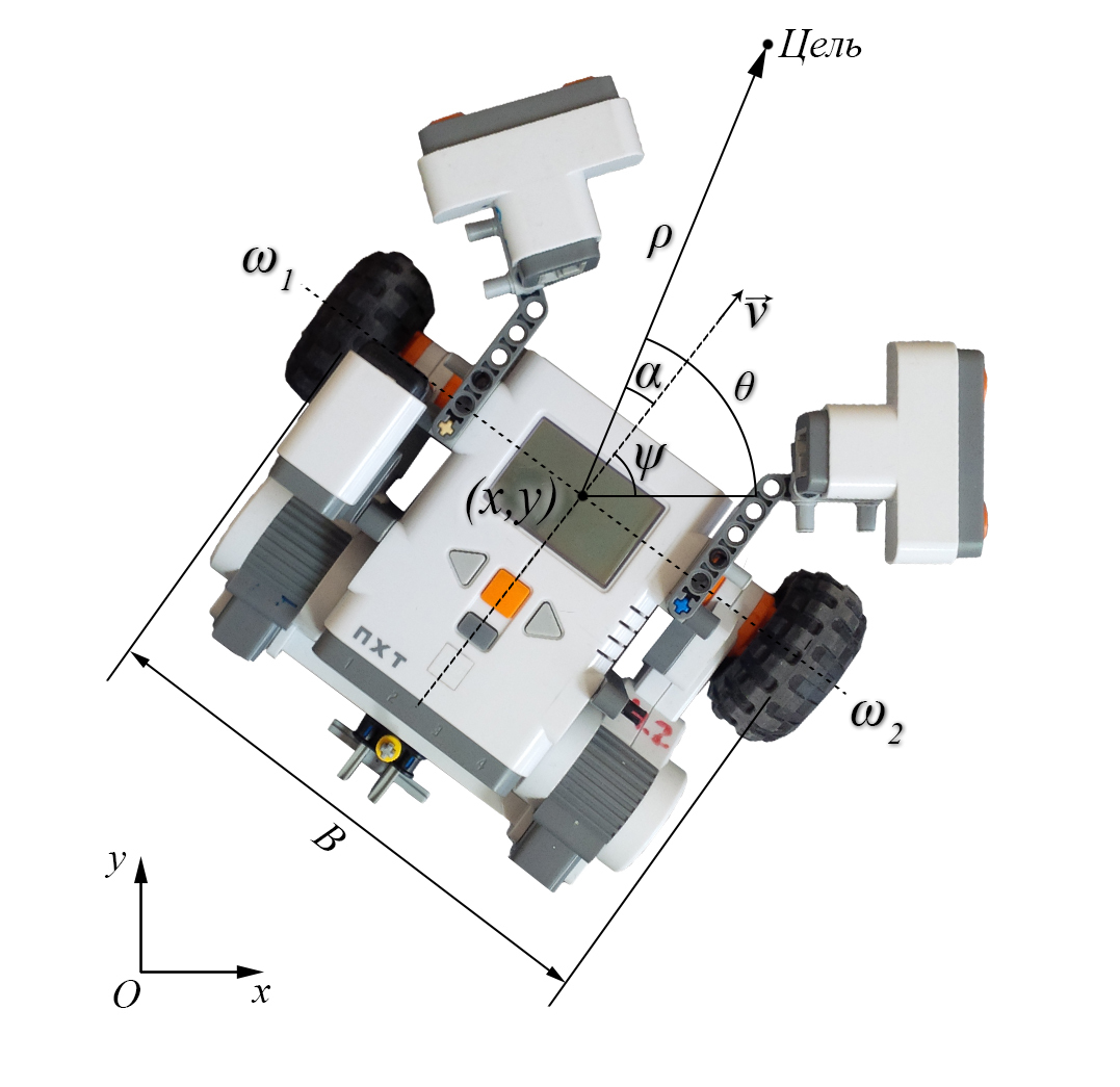
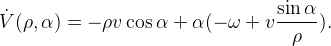
It should be noted that the figure indicates - distance to the target point;
  - azimuth, the angle between the axis OX and the direction to the target;
  - the course of the robot;
  - heading angle, the difference between the course and azimuth; v is the linear velocity of the robot. The robot moves due to the movement of two separately driven wheels. And such a kinematic scheme has a certain mathematical description:
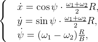
Where - the corresponding angular velocity of rotation of the wheels, x, y - the corresponding coordinates, R - the radius of the wheel, B - the distance between the wheels.
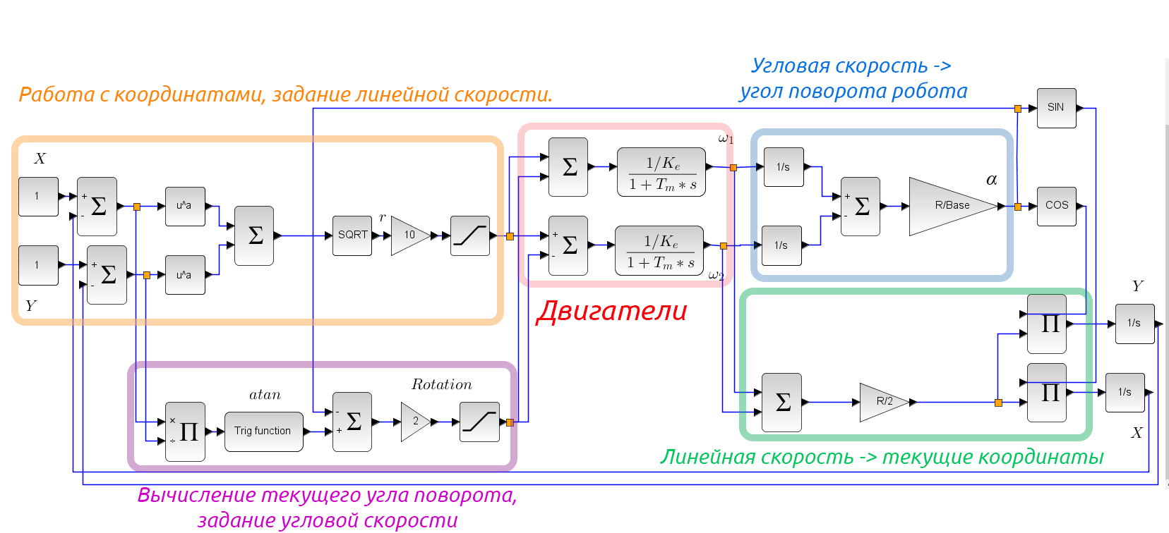
In principle, moving to a point with given coordinates can be solved using a P-controller, but in practice this will not be enough. Although everything works just fine in the model below:
')
The task is set as follows: the robot must reach the given coordinates .
.
When solving the problems of mobile robots navigation, two main approaches are used.
There are many local navigation methods, such as:
Let us dwell on the latter method. Having searched the network for information on how to control such a robot, one can find an article by A. Matveyeva, professor at the Department of Theoretical Cybernetics, St. Petersburg State University. and prof. Savkin A.V. from the University of New South Wales, Sydney, Australia about the robot navigation algorithm among moving and deformable obstacles. In the article, the authors argue that the most appropriate method for solving our problem is, in fact, the method of tangential avoidance, described by Mario Sarcinelli, professor of the Federal University of Espirintu-Santo, Vitoria, Brazil, whom we had the honor of meeting our team in Brazil .
To begin, let us describe the mathematical model describing the robot's navigation to the target, in polar coordinates:
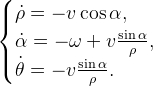
In fact, the robot can be fully controlled using angular and linear velocity values. therefore it is necessary to find such values so that the condition of the task is satisfied. . For this, the article proposes to use the apparatus of the Lyapunov function. This will be a quadratic function that includes the distance to the target and the course angle:

The time derivative should not be positive so that the distance to the target and the course angle do not increase. The derivative is as follows:

Expressing the derivative through the mathematical model proposed above, we obtain:
This derivative is negatively determined if we choose the following velocity values as the control action:
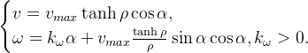
All this will allow the robot to achieve its goal, but so far only in the absence of obstacles. To avoid obstacles, it is necessary to amend the calculation of the course angle:

Where - the ratio of the proportional component of the course angle,
  - distance to the obstacle
  - the minimum distance to the obstacle.
With the help of the above method, the movement from point to point with a detour of obstacles was realized. The results are shown in the video, the error is due to wheel slip.
We also added an integral component for calculating the linear velocity to compensate for the friction of the motors. In the video below you can see that the robot quite accurately reaches the target in the vicinity of 3 centimeters.
The following is an example of a final program in the NXC c-like language:
This task is included in the discipline of robotics for the first and second year of our department, which in addition to it includes a segway, an inverted pendulum on a trolley, a Kapitsa pendulum, and a three-stage manipulator. As you can see, even with such simple equipment it is quite possible to disassemble serious robotic tasks.
Our research team, which is called the Student Design Bureau of the ITMO University ICS Department, continues to develop courses in robotics, and wants to share one of the latest projects on Lego NXT.
Previously, we published the course “Practical Robotics” on the NXT. Now this course is used to teach students in the department and on the “Open Education” platform. Fragments of this course were also published with a detailed description of actions for identifying an engine model and calculating a controller for a Segway robot .
This time it was decided to implement a detour detour by a robot with a differential drive. The design of the robot is quite simple: two wheels with engines, a gyroscope and a pair of ultrasonic sensors. To estimate the distance traveled, encoders on the motor shaft are used, for orientation of the robot, its angular velocity is measured by a gyroscope and the angle of rotation is calculated, and the distance to the obstacle is measured by ultrasonic range finders.
It should be noted that the figure indicates
- distance to the target point; - azimuth, the angle between the axis OX and the direction to the target; - the course of the robot; - heading angle, the difference between the course and azimuth; v is the linear velocity of the robot. The robot moves due to the movement of two separately driven wheels. And such a kinematic scheme has a certain mathematical description:Where
- the corresponding angular velocity of rotation of the wheels, x, y - the corresponding coordinates, R - the radius of the wheel, B - the distance between the wheels.In principle, moving to a point with given coordinates can be solved using a P-controller, but in practice this will not be enough. Although everything works just fine in the model below:
')
The task is set as follows: the robot must reach the given coordinates
.When solving the problems of mobile robots navigation, two main approaches are used.
- Global - determination of the absolute coordinates of the device when driving on long routes. The trajectory is chosen before the start of the movement based on the information received.
- Local - determination of device coordinates in relation to a certain (usually starting) point. Planning sets only a small segment of the trajectory, at the end point of which a further trajectory is chosen.
There are many local navigation methods, such as:
- histogram of the vector field Borenstein & Koren 1991 ;
- Khatib potential field , 1986 ; Rubagotti, Vedova, & Ferrara, 2011 ;
- diagram of close distances Minguez & Montano, 2004 ;
- tangential avoidance Ferreira, Pereira, Vassallo, Filho and Filho, 2008 .
Let us dwell on the latter method. Having searched the network for information on how to control such a robot, one can find an article by A. Matveyeva, professor at the Department of Theoretical Cybernetics, St. Petersburg State University. and prof. Savkin A.V. from the University of New South Wales, Sydney, Australia about the robot navigation algorithm among moving and deformable obstacles. In the article, the authors argue that the most appropriate method for solving our problem is, in fact, the method of tangential avoidance, described by Mario Sarcinelli, professor of the Federal University of Espirintu-Santo, Vitoria, Brazil, whom we had the honor of meeting our team in Brazil .
To begin, let us describe the mathematical model describing the robot's navigation to the target, in polar coordinates:
In fact, the robot can be fully controlled using angular and linear velocity values.
therefore it is necessary to find such values so that the condition of the task is satisfied. . For this, the article proposes to use the apparatus of the Lyapunov function. This will be a quadratic function that includes the distance to the target and the course angle:The time derivative should not be positive so that the distance to the target and the course angle do not increase. The derivative is as follows:
Expressing the derivative through the mathematical model proposed above, we obtain:
This derivative is negatively determined if we choose the following velocity values as the control action:
All this will allow the robot to achieve its goal, but so far only in the absence of obstacles. To avoid obstacles, it is necessary to amend the calculation of the course angle:
Where
- the ratio of the proportional component of the course angle, - distance to the obstacle - the minimum distance to the obstacle.With the help of the above method, the movement from point to point with a detour of obstacles was realized. The results are shown in the video, the error is due to wheel slip.
We also added an integral component for calculating the linear velocity to compensate for the friction of the motors. In the video below you can see that the robot quite accurately reaches the target in the vicinity of 3 centimeters.
The following is an example of a final program in the NXC c-like language:
Program code
#define RAD_WHEEL 0.028 // #define DEG2RAD PI / 180 #define LEFT OUT_C #define RIGHT OUT_B #define GYRO S1 #define LIMIT 20 // #define K_I 50 // #define K_P 0.1 // #define ERROR 0.03 // task main() { int rotA, rotB, // pwmLeft, pwmRight, // distS3, distS2, distMax, kDist, // currentTime, previousTime, dt, // gyroSpeed, gyroOffset, // fileSize = 30640; float course, courseAngle, bearing, // (psi), (alpha), (theta) xCoord, yCoord, // delthaX, delthaY, // length, intLength, // , path, prevPath, delthaPath, // xRef = -1, yRef = 0, // baseSpeed = 0, control = 0, // k = 20; string s; // byte handle; // SetSensorLowspeed(S2); SetSensorHTGyro(GYRO); // , DeleteFile("data.txt"); CreateFile("data.txt", fileSize, handle); Wait(50); // , (/) gyroOffset = SensorHTGyro(GYRO); course = 0; previousTime = CurrentTick(); while (true) { // distS3 = LIMIT - SensorUS(S3); distS2 = LIMIT - SensorUS(S2); // ( , ) if (distS3 < 0 ) distS3 = 0; if (distS2 < 0 ) distS2 = 0; if (distS2 > distS3) distMax = distS2; else distMax = distS3; kDist = sign(distS2 - distS3); currentTime = CurrentTick(); dt = currentTime - previousTime; previousTime = currentTime; // (/) gyroSpeed = SensorHTGyro(GYRO) - gyroOffset; // course = course + gyroSpeed * PI * dt / 1000.0 / 180.0; // rotA = MotorRotationCount(LEFT); rotB = MotorRotationCount(RIGHT); // path = (rotA + rotB) * DEG2RAD * RAD_WHEEL / 2; // delthaPath = path - prevPath; // prevPath = path; // X xCoord = xCoord + delthaPath * cos(course); // Y yCoord = yCoord + delthaPath * sin(course); // X delthaX = xRef - xCoord; // Y delthaY = yRef - yCoord; // bearing = atan2(delthaY, delthaX); // courseAngle = bearing - course - K_P * kDist * distMax; // if (abs(courseAngle) > PI) courseAngle = courseAngle - sign(courseAngle) * 2 * PI; // length = sqrt (delthaY * delthaY + delthaX * delthaX); intLength = intLength + length * dt / 1000; if (intLength > 10) intLength = 10; // baseSpeed = 100 * tanh (length) * cos (courseAngle) + K_I * intLength; if (abs(baseSpeed) > 40) baseSpeed = sign (baseSpeed) * 40; // control = k * courseAngle + sin(courseAngle) * baseSpeed / length; // if (abs(control) > 30) control = sign(control)*30; // float integer, pwmLeft = baseSpeed + control; // float integer, pwmRight = baseSpeed - control; if (abs(pwmLeft) > 100) pwmLeft = sign (pwmLeft) * 100; if (abs(pwmRight) > 100) pwmLeft = sign (pwmRight) * 100; // OnFwd(LEFT, pwmLeft); OnFwd(RIGHT, pwmRight); ClearScreen(); // NXT NumOut(0, 8, distS3); NumOut(0, 0, distS2); // s = NumToStr(xCoord) + " " + NumToStr(yCoord) + " " + NumToStr(bearing) + " " + NumToStr(course); // WriteLnString(handle, s, fileSize); // if(abs(length) < ERROR) { Off(OUT_BC); break; } Wait(5); } } This task is included in the discipline of robotics for the first and second year of our department, which in addition to it includes a segway, an inverted pendulum on a trolley, a Kapitsa pendulum, and a three-stage manipulator. As you can see, even with such simple equipment it is quite possible to disassemble serious robotic tasks.
Source: https://habr.com/ru/post/277829/
All Articles