Creating a user interface for Blend4Web (Part 1)
Sometimes I consider myself a pioneer, opening new pages using Blend4Web. This is a young engine, with an energetic development team, rich features and a lot of not-well-documented features. Something I scoop from the source of a large number of demos, pull developers on all sorts of questions, and most often I act by the method of “scientific poking”. In this article I want to share my work on creating a user interface for an application. And what is important, with the help of Blend4Web and HTML5 you can make quite a decent GUI game.
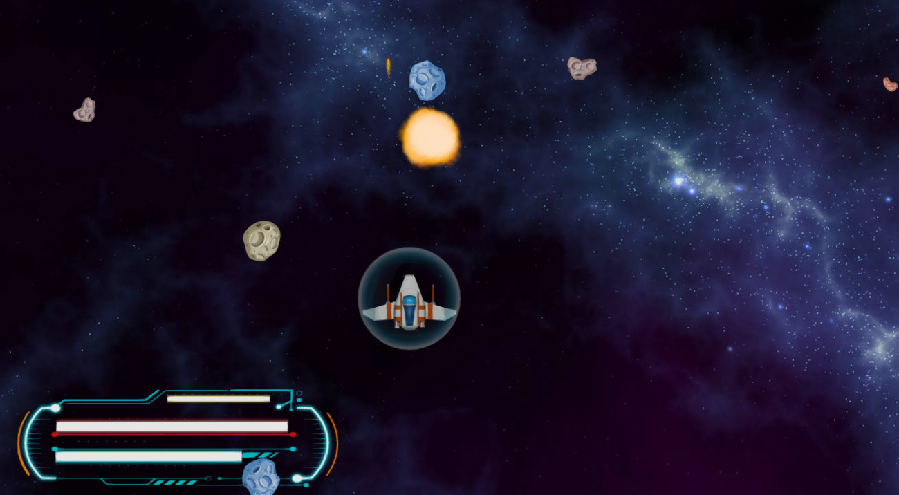
In the game, when the ships fly, successfully shooting hordes of meteorites and their own kind, I want to see a little more on the screen, that is, to receive any information about the gameplay. These are all sorts of text messages about missions or points earned, “life strips”, etc. All these elements can be created in two ways: using the HTML / CSS functions and through Blender / JavaScript.
In December 2015, the next Blend4Web release was released with a curious feature. The conversation is about the tool Viewport Alignment - it is nothing more than a tool for automatically aligning user interface elements with respect to the camera. It seems nothing surprising, but you need to know that the traditional GUI layout for the Blend4Web application is done using HTML / CSS. To me personally, this approach seems inconvenient and I prefer to do everything in Blender itself. Previously, it was difficult, because the interface “sprawled” when changing the resolution or proportions of the screen. It is now possible to avoid HTML problems and create GUIs directly in the Blender scene.
')
From the point of view of Blend4Web, the GUI element is no different from any object in the scene, except that it is tied to the active camera. All the magic is done in Blender itself.
GUI elements are traditionally considered two-dimensional, but in the case of Blend4Web, they are always three-dimensional objects. True, they can look different. The easiest option is to create a plane (Plane) with a stretched texture.
There is a handy plugin called “Import Images as Planes” , which is included in the basic Blender package. Its purpose is to create a plane with an already finished texture. It really speeds up the process, after all, just select the desired picture and it appears on the scene. But I do not recommend using this plugin for GUI for one simple reason - it is not optimal. It is desirable to store all drawn interface elements on one texture, i.e. create the so-called atlas.
You can draw the interface in anything, but it is important to fit everything on a texture with the same aspect ratio of a multiple of 4, for example, 512x512, 1024x1024. And do not get involved in size. Too small texture is bad, too big is also not very. So, the maximum size should be limited to a resolution of 2048x2048, although for me this is a lot. In general, it is considered to be good practice to output interface elements pixel to pixel, without any scaling. But in our case it is unrealistic, because each element is an ordinary three-dimensional object.
So it turns out that the creation of the interface is performed using standard Blender tools. Consider the basic steps:


So, in the scene there is a plane with a texture turned towards the camera. It is time to consider the Viewport Alignment tool (do not forget that the options of the Blend4Web engine will only be visible after selecting the same-named render).
Viewport Alignment allows you to “attach” the selected object to the borders or corners of the active camera. By doing this in Blender, you will be sure that the interface elements will remain in place regardless of the screen resolution.
First you need to create a parent-child relationship between your plane and the camera itself. Highlight Plane, and then Camera with the Shift key pressed. In the Object -> Parent menu, select Object . If everything is done correctly, then when moving the camera, the plane will obediently slide after it.
And only now will the Viewport Alignment options in the Object panel become available.

Turn on Viewport Alignment and select the desired side to bind from the menu. If you now try to export the scene and view the result in the browser, then most likely you will get an amazing result. The object will “stick” to the selected place, but it will not look at all like it was expected.
The panel has a Fit to Camera button. With its help, you can place an object in accordance with the chosen parameters of the reference and distance ( Distance option). Therefore, by clicking on it, you finally move the item to the right place. There is another nuance that for some reason is not explained in the official documentation.
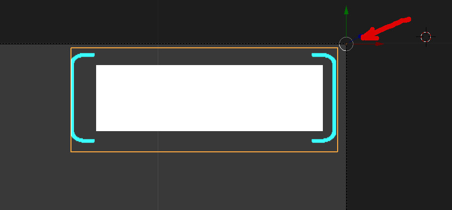
The fact is that the binding is performed depending on the center of the object. And for proper installation, it must be shifted in the right direction. The figure below highlights the center of the element, which is pressed to the top right corner.
To shift the center, go to edit mode ( Tab key). Place the 3D cursor in the desired place (by clicking the left mouse button) and select the menu item Object -> Transform -> Origin to 3D Cursor.
In this simple way, you can create any interface elements that are attached to the camera and automatically change their location when the screen resolution changes
By the way, even though I called this part of the lesson “Static Elements”, nothing prevents you from creating any animations for GUI elements. All this is done in the standard ways for Blender.
Do you think I'll start talking about cool animation effects? No, I will leave this fertile ground to other authors, and let me pass on to what topic ...
In the game, all kinds of indicators are very often needed: life, protection, weapon heating, etc. Their visual appearance depends on the current action. The hero is rich in “life” - a long strip, loses “life” and the strip decreases.
The simplest thing that comes to mind is to create object animation, say, with a change in scale. But we must also take into account the convenience of working with such an animation, because the size of the indicator must correspond to a certain numerical value. Therefore, the most advantageous is the change in geometry, the so-called vertex animation. Moreover, it is enough to create two forms: initial and final. And the transitions between them to perform from the code.
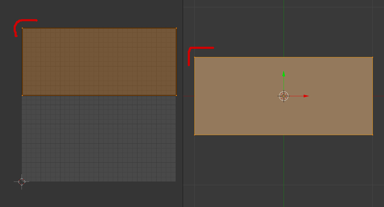
Algorithm for creating shape animation (see figure below):

If everything is done correctly, then when the Value value changes, the geometry of the object will change.
This is where the magic lies. The Blend4Web API allows you to control the Value parameter from code. Its values vary from 0 to 1, so it is easy to write a function to adapt any digital data in relation to the animation of the status bar.
A small example:
These are all sorts of messages, points earned and all that kind of thing that allows the player to get a return on the gameplay.
At first glance, Blend4Web has nothing to display textual information on the screen, not in the form of pictures or 3D, but of plain text itself. To be honest, I was at first confused when I tried to implement a simple printing of the Score. No native functions were found in the API. But there is an excellent mechanism for working with HTML5 Canvas. And already with his help with the text, you can work wonders.
Working with HTML5 canvas in the official documentation of the engine is considered very sparingly. Some important points are simply not taken into account. Hereinafter I will try to tell about them.
So, the basis of the canvas in the world of Blend4Web is any surface of a three-dimensional object. This means that you can display textual or other information on the canvas (for example, video), and then work with this object as you please. There are ample opportunities for the coolest effects. After all, the 3D model with canvas is no different from any other three-dimensional object - rotate, scale, apply animation and physics. Here is an example of working with canvas that the developers themselves give.
In my game for the Score, I used a simple rectangular plane attached to a corner of the screen. There is no need to apply any special settings to the carrier object. The material is created the most common, but the texture used is special.
Preparing an object surface for HTML5 Canvas output:
In principle, everything. Go to the code.
In the examples on the website Blend4Web there is a ready-made piece of code that literally displays text on the canvas. That's what I used in my project. I quote with some changes and additions.
There is nothing difficult in this code and it is hard-working to write a letter by a letter. The most interesting thing is the parameters of the HTML5 Canvas itself. Here are truly great opportunities. Consider some of them.
You can use not only system fonts, but also downloadable ones. To do this, add the following description to the CSS file:
In this case, the font initialization line will look like this:
Font color in RGBA format is set by the line:
You can change the alignment of the text inside the canvas. For example, in the center:
There are some effects with shadows:
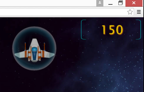
In the end, having played a little with the HTML5 Canvas features, I got the Score I demanded.
So, the traditional conclusions. Tool Viewport Alignment solves all the problems on the positioning of elements. Integration with HTML5 Canvas allows you to easily display information with a wide range of text effects. 3D + canvas is generally a unique feature for creating unusual three-dimensional menus, windows and more complex elements.
And here is a spoon of tar (wherever without it, then) - there is not enough tool to easily customize the output of information on HTML5 Canvas. With any change in the parameters of the canvas, you have to export the project to verify the result. This, of course, takes a lot of time for such experiments. But in general, there were no special problems in creating a custom UI for the Blend4Web application.
In the game, when the ships fly, successfully shooting hordes of meteorites and their own kind, I want to see a little more on the screen, that is, to receive any information about the gameplay. These are all sorts of text messages about missions or points earned, “life strips”, etc. All these elements can be created in two ways: using the HTML / CSS functions and through Blender / JavaScript.
In December 2015, the next Blend4Web release was released with a curious feature. The conversation is about the tool Viewport Alignment - it is nothing more than a tool for automatically aligning user interface elements with respect to the camera. It seems nothing surprising, but you need to know that the traditional GUI layout for the Blend4Web application is done using HTML / CSS. To me personally, this approach seems inconvenient and I prefer to do everything in Blender itself. Previously, it was difficult, because the interface “sprawled” when changing the resolution or proportions of the screen. It is now possible to avoid HTML problems and create GUIs directly in the Blender scene.
')
Static elements
From the point of view of Blend4Web, the GUI element is no different from any object in the scene, except that it is tied to the active camera. All the magic is done in Blender itself.
GUI elements are traditionally considered two-dimensional, but in the case of Blend4Web, they are always three-dimensional objects. True, they can look different. The easiest option is to create a plane (Plane) with a stretched texture.
There is a handy plugin called “Import Images as Planes” , which is included in the basic Blender package. Its purpose is to create a plane with an already finished texture. It really speeds up the process, after all, just select the desired picture and it appears on the scene. But I do not recommend using this plugin for GUI for one simple reason - it is not optimal. It is desirable to store all drawn interface elements on one texture, i.e. create the so-called atlas.
You can draw the interface in anything, but it is important to fit everything on a texture with the same aspect ratio of a multiple of 4, for example, 512x512, 1024x1024. And do not get involved in size. Too small texture is bad, too big is also not very. So, the maximum size should be limited to a resolution of 2048x2048, although for me this is a lot. In general, it is considered to be good practice to output interface elements pixel to pixel, without any scaling. But in our case it is unrealistic, because each element is an ordinary three-dimensional object.
So it turns out that the creation of the interface is performed using standard Blender tools. Consider the basic steps:
- Create a Plane primitive ( menu ADD | Mesh ). First, switch to the Camera view. When you add a Plane to the scene, pay attention to the additional panel on the left with the parameters of the created primitive. There is an option Align To View . If you activate it, Plane will turn to face the camera.
- Adjust the UV coordinates. It is more convenient to do this with the UV Editing window layout enabled. Select your plane, press Tab to go to edit mode and U -> Unwrap to set coordinates. Just pre-open in the next window the desired texture. Now, using standard Blender movement and scaling methods (hotkeys G and S), place the vertices of UV around the desired pattern.
- Create material and adjust texture. In principle, this action is no different from the usual work with materials in Blender. Look at the picture below. I outlined the key options for adjusting the texture and material with transparency. The Shadeless option is also included here . This is useful if you want your material to not respond to light sources.
So, in the scene there is a plane with a texture turned towards the camera. It is time to consider the Viewport Alignment tool (do not forget that the options of the Blend4Web engine will only be visible after selecting the same-named render).
Viewport Alignment allows you to “attach” the selected object to the borders or corners of the active camera. By doing this in Blender, you will be sure that the interface elements will remain in place regardless of the screen resolution.
First you need to create a parent-child relationship between your plane and the camera itself. Highlight Plane, and then Camera with the Shift key pressed. In the Object -> Parent menu, select Object . If everything is done correctly, then when moving the camera, the plane will obediently slide after it.
And only now will the Viewport Alignment options in the Object panel become available.
Turn on Viewport Alignment and select the desired side to bind from the menu. If you now try to export the scene and view the result in the browser, then most likely you will get an amazing result. The object will “stick” to the selected place, but it will not look at all like it was expected.
The panel has a Fit to Camera button. With its help, you can place an object in accordance with the chosen parameters of the reference and distance ( Distance option). Therefore, by clicking on it, you finally move the item to the right place. There is another nuance that for some reason is not explained in the official documentation.
The fact is that the binding is performed depending on the center of the object. And for proper installation, it must be shifted in the right direction. The figure below highlights the center of the element, which is pressed to the top right corner.
To shift the center, go to edit mode ( Tab key). Place the 3D cursor in the desired place (by clicking the left mouse button) and select the menu item Object -> Transform -> Origin to 3D Cursor.
In this simple way, you can create any interface elements that are attached to the camera and automatically change their location when the screen resolution changes
By the way, even though I called this part of the lesson “Static Elements”, nothing prevents you from creating any animations for GUI elements. All this is done in the standard ways for Blender.
Dynamic elements
Do you think I'll start talking about cool animation effects? No, I will leave this fertile ground to other authors, and let me pass on to what topic ...
In the game, all kinds of indicators are very often needed: life, protection, weapon heating, etc. Their visual appearance depends on the current action. The hero is rich in “life” - a long strip, loses “life” and the strip decreases.
The simplest thing that comes to mind is to create object animation, say, with a change in scale. But we must also take into account the convenience of working with such an animation, because the size of the indicator must correspond to a certain numerical value. Therefore, the most advantageous is the change in geometry, the so-called vertex animation. Moreover, it is enough to create two forms: initial and final. And the transitions between them to perform from the code.
Algorithm for creating shape animation (see figure below):
- Give the object its initial shape.
- Go to the Object Data panel and set the base key (in the screenshot it is called Basis).
- Add a new key (key 1) and set the Value to one.
- Go to edit mode and give the object a final shape.
- Open the Object panel and enable the Export Shape Keys option.
If everything is done correctly, then when the Value value changes, the geometry of the object will change.
This is where the magic lies. The Blend4Web API allows you to control the Value parameter from code. Its values vary from 0 to 1, so it is easy to write a function to adapt any digital data in relation to the animation of the status bar.
A small example:
... var m_scene = b4w.require("scenes"); var m_geom = b4w.require("geometry"); … // "Object Name" var obj = m_scene.get_object_by_name("Object Name"); // Value Key 1, 0.5 (50%) m_geom.set_shape_key_value(obj , "Key 1", 0.5); ... Text output
These are all sorts of messages, points earned and all that kind of thing that allows the player to get a return on the gameplay.
At first glance, Blend4Web has nothing to display textual information on the screen, not in the form of pictures or 3D, but of plain text itself. To be honest, I was at first confused when I tried to implement a simple printing of the Score. No native functions were found in the API. But there is an excellent mechanism for working with HTML5 Canvas. And already with his help with the text, you can work wonders.
Working with HTML5 canvas in the official documentation of the engine is considered very sparingly. Some important points are simply not taken into account. Hereinafter I will try to tell about them.
So, the basis of the canvas in the world of Blend4Web is any surface of a three-dimensional object. This means that you can display textual or other information on the canvas (for example, video), and then work with this object as you please. There are ample opportunities for the coolest effects. After all, the 3D model with canvas is no different from any other three-dimensional object - rotate, scale, apply animation and physics. Here is an example of working with canvas that the developers themselves give.
In my game for the Score, I used a simple rectangular plane attached to a corner of the screen. There is no need to apply any special settings to the carrier object. The material is created the most common, but the texture used is special.
Preparing an object surface for HTML5 Canvas output:
- Create a UV scan for the plane where the canvas is supposed to be displayed. Be careful and start placing your UV grid from the top of the texture. For some reason, I initially placed UV at the bottom of the texture and lost a lot of time trying to figure out why there is no rendering.
- Add a new None texture to the texture slot of the material. Give it a normal name.
- In the texture options, set the Source Type as Canvas.
In principle, everything. Go to the code.
In the examples on the website Blend4Web there is a ready-made piece of code that literally displays text on the canvas. That's what I used in my project. I quote with some changes and additions.
… var m_tex = b4w.require("textures"); var m_scene = b4w.require("scenes"); ... // var text = ["Hello”, “World!"]; var MARGIN_LEFT = 250; var LINE_SPACING = 10; var MARGIN_TOP = 120; // - var obj = m_scene.get_object_by_name("Object"); // var ctx_image = m_tex.get_canvas_ctx(obj, "tex_id"); var font = ctx_image.font.split("px"); var font_height = parseInt(font[0]); //HTML5 Canvas ctx_image.fillStyle = "rgba(255,230,0,255)"; ctx_image.clearRect(0,0,512,512); ctx_image.font = "120px Arial"; ctx_image.textAlign = "start"; // for (var i = 0; i < text.length; i++) ctx_image.fillText(text[i], MARGIN_LEFT, Math.round(LINE_SPACING * font_height * i + MARGIN_TOP)); // m_tex.update_canvas_ctx(obj, "tex_id"); There is nothing difficult in this code and it is hard-working to write a letter by a letter. The most interesting thing is the parameters of the HTML5 Canvas itself. Here are truly great opportunities. Consider some of them.
HTML5 Canvas Magic
You can use not only system fonts, but also downloadable ones. To do this, add the following description to the CSS file:
@font-face { font-family: MyFont; src: url(fonts/MyFont.ttf); } In this case, the font initialization line will look like this:
ctx_image.font = "120px MyFont"; Font color in RGBA format is set by the line:
ctx_image.fillStyle = "rgba(255,230,0,255)"; You can change the alignment of the text inside the canvas. For example, in the center:
ctx_image.textAlign = "center"; There are some effects with shadows:
ctx_image.shadowOffsetX = 5; ctx_image.shadowOffsetY = 5; ctx_image.shadowBlur = 10; ctx_image.shadowColor = "rgba(255, 132, 0, 1)"; In the end, having played a little with the HTML5 Canvas features, I got the Score I demanded.
So, the traditional conclusions. Tool Viewport Alignment solves all the problems on the positioning of elements. Integration with HTML5 Canvas allows you to easily display information with a wide range of text effects. 3D + canvas is generally a unique feature for creating unusual three-dimensional menus, windows and more complex elements.
And here is a spoon of tar (wherever without it, then) - there is not enough tool to easily customize the output of information on HTML5 Canvas. With any change in the parameters of the canvas, you have to export the project to verify the result. This, of course, takes a lot of time for such experiments. But in general, there were no special problems in creating a custom UI for the Blend4Web application.
Source: https://habr.com/ru/post/277533/
All Articles